EP4470902A2 - Gréement à aile - Google Patents
Gréement à aile Download PDFInfo
- Publication number
- EP4470902A2 EP4470902A2 EP24208200.6A EP24208200A EP4470902A2 EP 4470902 A2 EP4470902 A2 EP 4470902A2 EP 24208200 A EP24208200 A EP 24208200A EP 4470902 A2 EP4470902 A2 EP 4470902A2
- Authority
- EP
- European Patent Office
- Prior art keywords
- boom
- wing rig
- leading edge
- edge
- wing
- Prior art date
- Legal status (The legal status is an assumption and is not a legal conclusion. Google has not performed a legal analysis and makes no representation as to the accuracy of the status listed.)
- Pending
Links
Images


Classifications
-
- B—PERFORMING OPERATIONS; TRANSPORTING
- B63—SHIPS OR OTHER WATERBORNE VESSELS; RELATED EQUIPMENT
- B63H—MARINE PROPULSION OR STEERING
- B63H8/00—Sail or rigging arrangements specially adapted for water sports boards, e.g. for windsurfing or kitesurfing
- B63H8/10—Kite-sails; Kite-wings; Control thereof; Safety means therefor
-
- B—PERFORMING OPERATIONS; TRANSPORTING
- B63—SHIPS OR OTHER WATERBORNE VESSELS; RELATED EQUIPMENT
- B63H—MARINE PROPULSION OR STEERING
- B63H9/00—Marine propulsion provided directly by wind power
- B63H9/04—Marine propulsion provided directly by wind power using sails or like wind-catching surfaces
- B63H9/06—Types of sail; Constructional features of sails; Arrangements thereof on vessels
- B63H9/067—Sails characterised by their construction or manufacturing process
-
- B—PERFORMING OPERATIONS; TRANSPORTING
- B63—SHIPS OR OTHER WATERBORNE VESSELS; RELATED EQUIPMENT
- B63H—MARINE PROPULSION OR STEERING
- B63H8/00—Sail or rigging arrangements specially adapted for water sports boards, e.g. for windsurfing or kitesurfing
- B63H8/10—Kite-sails; Kite-wings; Control thereof; Safety means therefor
- B63H8/16—Control arrangements, e.g. control bars or control lines
-
- B—PERFORMING OPERATIONS; TRANSPORTING
- B63—SHIPS OR OTHER WATERBORNE VESSELS; RELATED EQUIPMENT
- B63H—MARINE PROPULSION OR STEERING
- B63H8/00—Sail or rigging arrangements specially adapted for water sports boards, e.g. for windsurfing or kitesurfing
- B63H8/10—Kite-sails; Kite-wings; Control thereof; Safety means therefor
- B63H8/12—Kites with inflatable closed compartments
Definitions
- the invention relates to a hand-supported wing rig for wind-powered sports, for example foil surfing (wing foil), according to the preamble of patent claim 1.
- Such a wing rig is described on the Internet under the name "Slingwing”. It is essentially a kite with a leading edge and a single strut, which are designed to be inflatable. There are holding loops on the central strut and on the leading edge, which the user uses to hold the inflatable wing rig during use, for example when foiling, ice skating or skiing.
- This inflatable wing rig which is adapted to the aerodynamics of kites, is severely deformed during use, especially at the high speeds reached during foiling, thus worsening the aerodynamics.
- a rigid wing rig in which the leading edge and a boom are formed by a complex tube construction that spans a canvas (canopy).
- the leading edge is curved in an arc shape when viewed from above.
- the boom is supported by a large number of struts on the leading edge. These struts are designed in such a way that they give the leading edge a concave structure when viewed from the front, i.e. in the direction of flow of the wing rig, according to which the end sections (tips) of the wing rig are flared upwards from a central vertex of the leading edge.
- a disadvantage of this solution is that the total weight of the wing rig is very high due to the complex structure of the boom and the leading edge, so that use in water sports is only possible with appropriate buoyancy bodies.
- Another disadvantage is that the assembly and disassembly of the wing rig is difficult due to the complex tube structure takes a lot of time. This hard tube structure of the front edge and the boom also poses a significant risk of injury to the user in the event of a catastrophic fall.
- a similar rigid wing rig is in the WO 95/05973 A1 shown.
- the leading edge and the boom are formed by a complex tube structure.
- the structure shows the same disadvantages as the wing rig according to the above-discussed US 4,563,969 .
- leading edge is formed by two V-shaped masts that are connected to each other via a central boom and support struts.
- This wing rig is also very heavy due to its tubular structure, which makes handling particularly difficult for water sports.
- the DE 34 06 040 A1 shows a sail drive for flying with a sailboard in which two kite sails are connected to each other at side corners.
- the GB 2 203 113 A shows an inflatable wing structure with a triangular inflatable guide structure within which a sailcloth is stretched.
- the hand-supported wing rig according to the invention is suitable for wind-powered sports, for example for foil surfing and the high speeds associated with it.
- the wing rig has an inflatable front edge from which a boom extends, with the front edge and the boom stretching a sailcloth.
- the wing rig is held in particular by the boom during use.
- the front edge is curved in a plan view from a connection of the boom away to the leech (trailing edge) of the sailcloth in an approximately arched, delta-shaped, U-shaped or C-shaped manner.
- the front edge is approximately V-shaped in a front view viewed in the direction of flow when not exposed to airflow or unloaded, with this profile converging towards the boom. In other words, the profile opens upwards during use, away from the rider.
- the boom is preferably designed as a rigid, non-inflatable component.
- the term "rigid component” refers to a structure made of a largely dimensionally stable material, but this can easily be dismantled or made telescopic.
- the boom is designed in such a way that it is easier to hold the wing rig during use.
- the tree is preferably designed with a sheath that improves the grip/friction.
- the approximately V-shaped profile runs from the leading edge to the trailing edge of the sailcloth. This means that the entire wing rigging profile is profiled so that it opens upwards when viewed from the front (in the direction of flow).
- the aerodynamics are further improved if the inclination angle in the tip area is between 0° and 20°, preferably more than 1°, preferably about 5°.
- the wing rig is designed such that the average angle of inclination, i.e. the angle from the apex of the leading edge to the respective end section, is 5° to 20°, preferably about 10°.
- the boom can be telescopic or made up of several interchangeable sections.
- the flight stability of the wing rig is further improved if the boom mount is designed in such a way that it prevents rotation of the leading edge around its longitudinal axis.
- the holder encompasses the front edge in sections and thus prevents rotation.
- the bracket can also pass through the front edge.
- appropriate receptacles for the bracket or the boom must be formed on the front edge.
- a channel should be provided into which the bracket or the boom can be inserted.
- the boom is designed without braces.
- This type of solution is weight-optimized and also allows the user to hold the boom and thus the wing rig variably depending on the respective driving maneuver and the environmental conditions.
- the centre of gravity is at least more than 40 percent of the distance between the apex of the leading edge and the trailing edge (leech) from the leading edge.
- leading edge and/or the sailcloth can be stiffened by means of stiffening elements, such as sail battens.
- These sail battens can in turn be curved and/or tapered to shape the wing profile.
- a sail batten extends from the leading edge to the trailing edge, said sail batten being positioned such that it lies in a vertical plane with the boom (when the wing rig is aligned horizontally).
- a handle can be provided in the connection area of the tree, preferably at the front edge.
- the bracket for connecting the boom to the front edge can, for example, be formed by a profile piece that surrounds the front edge in sections and is attached to the front edge using suitable fastening means. The boom is then inserted into the profile piece or connected to it in some other way.
- An alternative solution is to create a holder for the boom on the front edge using profile parts or canvas. These profile parts then enclose the front edge in sections, preventing the front edge from rotating during use.
- the boom preferably extends from the leading edge to the trailing edge without being directly or firmly connected to the sailcloth in the areas in between, so that practically the entire length of the boom is available as a grip area. This ensures that the wing rig can be held optimally according to the user's preferences during any maneuver. Furthermore, the profile depth can be adjusted by adjusting the boom length.
- the structure of the wing rig is designed in such a way that when exposed to airflow, i.e. when the wing rig is in use, the opening angle in the area of the trailing edge is reduced. This means that the angle of inclination ⁇ of the trailing edge areas to the horizontal increases during use. Accordingly, the profile depth can also increase when exposed to airflow.
- the change in the opening angle can be greater in the trailing edge area than in the leading edge area.
- the boom is preferably attached to the area facing away from the canvas at the apex of the leading edge.
- the attachment is such that the wing rig can be swivelled/adjusted sideways by turning the boom around its longitudinal axis - this would not be possible with loops (handles) as these are not rigid and therefore no torque can be applied.
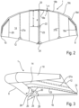
- FIG. 1 The use of a wing rig 1 according to the invention for driving a foil board 2 is shown.
- a surfer 4 holds the wing rig 1 only with his hands and adjusts it in relation to the wind depending on the desired Direction of travel (upwind, beam reach, downwind) or the lift to be adjusted, for example when jumping or adjusting the altitude.
- the wing rig 1 has an inflatable leading edge 6, which in plan view (from above into the Figures 1 and 2 ) is approximately arched, preferably approximately delta-, C- or U-shaped and extends with its tips 8, 10 up to a rear edge 12 of a sailcloth 14 of the wing rig 1.
- this sailcloth 14 is supported on the one hand by the front edge 6 and on the other hand by a boom 16 explained in more detail below (see Figure 3 ) is stretched out.
- the surfer 4 holds the wing rig 1 only by the boom 16, which is pointing downwards (view from Figure 1 ).
- the boom 16 is preferably provided with a casing that simplifies/optimizes gripping and holding.
- the front edge 6 is protruding both in plan view ( Figure 2 ) as well as in a front view - seen in the direction of flow - (see Figure 4 ) V-shaped, with the V/U extending upwards in the front view, ie, away from the surfer.
- the rear edge 12 and thus the entire canopy surface 14 is V- (or U-) shaped in the front view.
- Figure 2 shows a top view of the wing rig 1 according to Figure 1 .
- the leading edge 6 which is approximately arched or delta-shaped, in the broadest sense approximately U-shaped or C-shaped, and which extends to the trailing edge 12 of the sailcloth 14.
- the leading edge 6 is formed in the manner of a kite by a front tube in which a bladder is accommodated, which is inflated via a valve, the pressure being selected such that the structure of the wing rig 1 is guaranteed even at high wind strengths and speeds.
- the leading edge 6 is formed by a plurality of tube segments 18a, 18b, 18c, 18d, 18e (for the sake of simplicity, only one half of the trailing edge 12 is provided with reference numerals), the angle of attack ⁇ of which to the horizontal in Figure 2 (ie, for example, to a connecting line between the two end sections 8, 10) from a vertex 20 to the end sections 8, 10.
- This angle of attack ⁇ is shown as an example in the tube segment 18a.
- the reference number 22 indicates the The centre of gravity of the area (centre of the sailcloth) is marked. This centre of gravity 22 is offset from the apex 20 by at least 40 percent of the distance between the apex 20 and the corresponding apex 24 of the trailing edge 12.
- the distance between the apex 20, 24 is in Figure 2 marked with the reference symbol a. Accordingly, the distance b between the vertex 20 and the centroid 22 is at least 40 percent of the distance a.
- This area centre of gravity 22 is selected such that the surfer 4 can optimally grasp the boom 16, which will be explained in more detail below, and thus support the acting wind forces in order to, for example, sail an optimal upwind course.
- a central center sail batten 23 and two sail battens 27a, 27b offset towards the end sections 8, 10 are provided, which extend between the front edge 4 and the rear edge 12 and are inserted into corresponding sail batten pockets of the sailcloth 14.
- This insertion takes place in a manner known per se with a certain pre-tension, which is selected according to the desired profile or can also be changed in order to be able to adapt the profile to different wind strengths.
- the reference number 29 in Figure 2 Seams of the sailcloth 14 are also shown, which is made up of several panels. It may also be sufficient to design the panels in such a way that they are only sewn in the area of the sail battens or run continuously from tip 8 to tip 10.
- the boom 16 and the center batten 23 are thus in the same vertical plane, which in Figure 2 perpendicular to the plane of the drawing and in Figure 3 is in the plane of the drawing.
- the space between the boom and the sail batten 23 / sailcloth 14 is thus free, so that the surfer can freely choose his grip position depending on the maneuver/course.
- the front edge 6 is also perpendicular to the plane of the drawing in Figure 2 profiled. Specifically, the front edge 6 is V-shaped from the apex 20 to the end sections 8, 10, whereby the V (also called opening angle ⁇ ) - as in Figure 1 shown - upwards, ie, away from the boom 16.
- This V-profile is also formed accordingly in the area of the canvas 14. This is achieved, among other things, by the boom 16 reaching the apex 24 in the illustration according to Figure 3 downwards, ie, away from the end sections 8, 10, thus forming the V-shape which is determined by the opening angle ⁇ .
- the structure of the wing rig 1 is designed such that this opening angle ⁇ is reduced when exposed to the flow, since the end sections 8, 10 deflect upwards (away from the surfer 4) due to the load.
- the boom 16 thereby acts on the area of the apex 20 of the leading edge 6 which is spaced apart from the sailcloth 14 (at the bottom).
- the V-shape is particularly evident in the front view according to Figure 4 visible.
- the front edge 6 formed by the tube is arranged facing the viewer.
- the canvas 14 is accordingly V-shaped.
- the angle of inclination ⁇ of the leading edge 6 in the area of the apex is a maximum of 20°.
- this angle of inclination ⁇ i.e. the angle between the horizontal (parallel to the connecting line of the end sections 8, 10) and the tube segment 18a, is approximately 20°, for example.
- the next tube segment 18b is then set somewhat flatter, so that the angle is, for example, 15°.
- the angle of inclination of the following segments 18c, 18d, 18e is then again flatter, whereby the angle of inclination ⁇ in the area of the segment 18c can be, for example, 5°.
- the "average" angle of inclination ⁇ seen over the entire wing rig 1 is, for example, 10°, so that the "average" opening angle is then approximately 160°.
- the boom 16 is designed without braces - this is a significant difference to the complex constructions described at the beginning, in which the boom is designed with a large number of transverse and diagonal braces.
- the boom 16 can be detachably attached to the apex 20 of the front edge 6 via a holder 25.
- the holder 25 has a support bracket 26 which is designed to correspond to the outer contour of the apex 20 and surrounds it in sections. This surround is carried out in such a way that, in the event of comparatively high wind pressure, rotation of the tube, i.e. of the tube segments 18a forming the apex 20 in the direction of the arrow and thus twisting of the profile is reliably prevented.
- the support bracket 26 is then followed in the direction of the boom 16 by a holder 28 into which the boom 16 is inserted.
- the end sections of the support bracket 26 and the holder 28 are connected via an arched handle 30, which makes it easier for the surfer 4 to handle the wing rig 1 before and after use.
- the wing rig 1 can be held by the handle 30 when not in use in order to let it blow away in the wind.
- the holder 25 and the boom 16 are preferably made of a light material, for example aluminum, fiber-reinforced plastic, carbon fiber materials or other high-strength lightweight materials. Due to the simple structure of the boom 16, this has an insignificant influence on the overall weight of the wing rig 1.
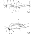
- Figure 5 shows a side view of a variant of the previously described embodiment of a wing rig 1.
- the view corresponds approximately to that of Figure 3 .
- the apex 24 of the rear edge 12 is pushed downwards by the tree 16 (view from Figure 5
- the bracket 25 of the tree 16 has a receptacle 28 into which the tree 16 is inserted or which is connected to the tree 16 in some other way.
- the apex 20 is supported according to Figure 6 on the top of the holder 28.
- a lightweight, approximately U-shaped handle 32 extends away from the holder 28, the end section of which engages the apex 20 formed by the tube segments 18a at a distance from the support of the apex 20 on the holder 28, i.e. offset towards the canvas 14.
- the spacing of the support of the apex 20 on the holder 28 on the one hand and on the end section 34 of the handle 32 on the other hand also prevents the above-described rotation of the front edge 6 (front tube).
- the U-structure of the handle 32 allows the wing rig 1 to be easily held for blowing out.
- the handle 32 is designed as a framework structure.
- the connection of the receptacle 28 and the end section 34 to the apex can be formed via suitable fixing elements on the tube segments 18a. These fixing elements are preferably designed such that the handle 30 is detachably connected to the front edge 6 (front tube).
- the handle 32 which is more or less integrated into the tree structure, this can also be designed as a loop on the inflow side of the leading edge 6, so that the surfer can let the wing rig 1 blow out while holding it in his hand while surfing, for example.
- Figure 7 shows an embodiment in which the holder 25 is designed as a flat body which is designed to encompass the rear edge 6 or the tube segments 18a in sections.
- This flat holder can be designed as a molded body, for example.
- the holder 25 is made of canvas that is connected to the apex 20 of the front edge 6 and is stabilized by suitable stiffening elements if necessary.
- the boom 16 can then be inserted into this holder 25.
- the holder 25 is designed in such a way that rotation of the tube (front edge 6) in the direction of the arrow is prevented by the support by the boom 16.
- the front tube is designed with a continuous bladder, as explained.
- a separate bladder is used for each half of the wing rig, whereby between these two bladders as shown in Figure 8 a support channel 36 remains, into which the boom 16 is inserted.
- This support channel 36 can, for example, be formed by a piece of pipe which passes diametrically through the front tube.
- This support channel 36 is formed between the two bladders of the two wing rig halves (left, right).
- a bearing ring 40 is formed on an outer shell 38 of the front tube (front edge 6), which runs as an extension of the support channel 36 and through which the boom 16 passes.
- This bearing ring 40 absorbs the compression forces and is designed in a similar way to the support rings of the commonly used kite valves.
- a similar support ring 42 is provided opposite the bearing ring 40 on the inside of the outer shell 38, on which the Figure 8 left end section of the boom 16 is supported.
- the tubular support channel 36 is connected to the bearing ring 40 on the one hand and the support ring 42 on the other hand, so that the boom 16 is reliably fixed in position.
- Such a solution has the advantage that the bearing rings 40 and the support rings 42 can be used for practically any front tube diameter - only the length of the support channel 36 has to be adjusted.
- the boom 16 is very stably supported, so that the holding forces introduced by the surfer 4 and also the compression forces transmitted by the front tube are reliably absorbed without the boom 16 being excessively deformed.
- the support channel 36 and the rings 40, 42 are preferably designed as plastic injection molded parts.
- the sailcloth 14 can be stabilized using sail battens or the like. These sail battens can be conical or profiled in order to optimize the flow profile of the sailcloth 14.
- the leading edge 16 can also be stiffened using suitable stiffening elements so that the wing rig 1 maintains the aerodynamically optimized shape shown even under high loads.
- These sail battens or stiffening elements can also be designed as carbon fiber tubes or the like.
- the sail battens are profiled in such a way that they are first adapted to the diameter of the front edge 6 (front tube) and then support the sailcloth 14.
- sail battens can be inserted into the sailcloth 14 from the rear edge 12.
- wing rig 1 In order to prevent the wing rig 1 from drifting away in the event of a fall, it is connected to the surfer 4, in particular to his arm, via a safety leash 44.
- a hand-supported wing rig which is preferably designed with an inflatable leading edge, which is designed to widen upwards (away from the surfer) in the direction of flow in an approximately V-shape.
Landscapes
- Engineering & Computer Science (AREA)
- Chemical & Material Sciences (AREA)
- Combustion & Propulsion (AREA)
- Mechanical Engineering (AREA)
- Ocean & Marine Engineering (AREA)
- Sustainable Energy (AREA)
- Life Sciences & Earth Sciences (AREA)
- Sustainable Development (AREA)
- Manufacturing & Machinery (AREA)
- Toys (AREA)
- Wind Motors (AREA)
- Structures Of Non-Positive Displacement Pumps (AREA)
- Executing Machine-Instructions (AREA)
- Pyrane Compounds (AREA)
- Transition And Organic Metals Composition Catalysts For Addition Polymerization (AREA)
- Tents Or Canopies (AREA)
Applications Claiming Priority (4)
| Application Number | Priority Date | Filing Date | Title |
|---|---|---|---|
| DE102019101656.8A DE102019101656B4 (de) | 2019-01-23 | 2019-01-23 | Flügelrigg |
| EP23177722.8A EP4234389B1 (fr) | 2019-01-23 | 2020-01-22 | Gréement aile |
| EP20701589.2A EP3914510B2 (fr) | 2019-01-23 | 2020-01-22 | Gréement aile |
| PCT/EP2020/051463 WO2020152198A1 (fr) | 2019-01-23 | 2020-01-22 | Gréement aile |
Related Parent Applications (3)
| Application Number | Title | Priority Date | Filing Date |
|---|---|---|---|
| EP20701589.2A Division-Into EP3914510B2 (fr) | 2019-01-23 | 2020-01-22 | Gréement aile |
| EP20701589.2A Division EP3914510B2 (fr) | 2019-01-23 | 2020-01-22 | Gréement aile |
| EP23177722.8A Division EP4234389B1 (fr) | 2019-01-23 | 2020-01-22 | Gréement aile |
Publications (2)
| Publication Number | Publication Date |
|---|---|
| EP4470902A2 true EP4470902A2 (fr) | 2024-12-04 |
| EP4470902A3 EP4470902A3 (fr) | 2025-03-19 |
Family
ID=69187793
Family Applications (3)
| Application Number | Title | Priority Date | Filing Date |
|---|---|---|---|
| EP20701589.2A Active EP3914510B2 (fr) | 2019-01-23 | 2020-01-22 | Gréement aile |
| EP23177722.8A Active EP4234389B1 (fr) | 2019-01-23 | 2020-01-22 | Gréement aile |
| EP24208200.6A Pending EP4470902A3 (fr) | 2019-01-23 | 2020-01-22 | Gréement à aile |
Family Applications Before (2)
| Application Number | Title | Priority Date | Filing Date |
|---|---|---|---|
| EP20701589.2A Active EP3914510B2 (fr) | 2019-01-23 | 2020-01-22 | Gréement aile |
| EP23177722.8A Active EP4234389B1 (fr) | 2019-01-23 | 2020-01-22 | Gréement aile |
Country Status (5)
| Country | Link |
|---|---|
| US (1) | US11738840B2 (fr) |
| EP (3) | EP3914510B2 (fr) |
| DE (2) | DE102019101656B4 (fr) |
| ES (1) | ES2952068T5 (fr) |
| WO (1) | WO2020152198A1 (fr) |
Families Citing this family (16)
| Publication number | Priority date | Publication date | Assignee | Title |
|---|---|---|---|---|
| DE102020122145A1 (de) | 2019-10-31 | 2021-05-06 | Boards & More Gmbh | Flügelrigg |
| DE102019129493A1 (de) | 2019-10-31 | 2021-05-06 | Boards & More Gmbh | Kite und Flügelrigg |
| DE102020122143A1 (de) | 2019-10-31 | 2021-05-06 | Boards & More Gmbh | Flügelrigg |
| DE102021106993B4 (de) | 2020-08-17 | 2024-10-31 | Boards & More Gmbh | Flügelrigg |
| DE202021101663U1 (de) | 2020-08-17 | 2021-06-22 | Boards & More Gmbh | Flügelrigg |
| ES2988746T3 (es) | 2020-12-29 | 2024-11-21 | Boards & More Gmbh | Aparejo de ala |
| FR3121657A1 (fr) | 2021-04-12 | 2022-10-14 | F. One | Aile de traction autonome |
| WO2022218921A1 (fr) | 2021-04-12 | 2022-10-20 | F. One | Aile de traction autonome |
| DE102021125438A1 (de) | 2021-04-15 | 2022-10-20 | Boards & More Gmbh | Flügelrigg |
| EP4323272B1 (fr) | 2021-04-15 | 2026-02-04 | Boards & More GmbH | Gréement et aile |
| US12157551B2 (en) * | 2021-10-27 | 2024-12-03 | Douglas A. Dockray | Power assisted devices for generating force for powering a user on a vehicle in kiteboarding, wing foiling, paddleboarding, and the like |
| DE102021214265A1 (de) | 2021-12-13 | 2023-06-15 | Boards & More Gmbh | Wing |
| IT202200006818A1 (it) * | 2022-04-06 | 2023-10-06 | Zm Design S R L | Vela alare gonfiabile con bordo anteriore aerodinamicamente ottimizzato |
| FR3142746B1 (fr) * | 2022-12-01 | 2026-04-24 | Le Bail Roland | Voile libre à géométrie particulière combinant structure et préhension |
| EP4400407B1 (fr) * | 2023-01-12 | 2025-06-04 | Ozone Kites Ltd. | Voile d'aile |
| FR3155807A1 (fr) | 2023-11-24 | 2025-05-30 | sylvain barrière | Aile de traction supportée manuellement escamotable |
Citations (7)
| Publication number | Priority date | Publication date | Assignee | Title |
|---|---|---|---|---|
| DE3140685A1 (de) | 1981-10-13 | 1983-04-28 | James R. 90402 Santa Monica Calif. Drake | "handsegel" |
| DE3406040A1 (de) | 1983-10-18 | 1985-08-22 | Otto Dr.med. 5000 Köln Jung | Drachenrigg |
| US4563969A (en) | 1981-03-11 | 1986-01-14 | Le Bail Roland C | Sail having variable propelling and lifting effects |
| US4742977A (en) | 1986-11-03 | 1988-05-10 | Crowell Robert L | Wing structure with self-induced camber |
| GB2203113A (en) | 1987-03-16 | 1988-10-12 | Barry John Jacobson | An inflatable aerodynamic wing structure |
| WO1995005973A1 (fr) | 1993-08-20 | 1995-03-02 | Oy Skywings Ab | Voile en forme d'aile |
| US5448961A (en) | 1992-07-13 | 1995-09-12 | Ansteensen; Erik | User supported portable sail |
Family Cites Families (11)
| Publication number | Priority date | Publication date | Assignee | Title |
|---|---|---|---|---|
| US3487800A (en) * | 1968-03-27 | 1970-01-06 | Hoyle Schweitzer | Wind-propelled apparatus |
| US4533159A (en) * | 1984-04-27 | 1985-08-06 | Seidel John C | Wind propulsion apparatus |
| DE3421503A1 (de) * | 1984-06-08 | 1985-12-12 | Fritz 8200 Rosenheim Eib | Leichtbautragfluegel |
| EP0198065A1 (fr) | 1984-10-17 | 1986-10-22 | CROWELL, Robert Lee | Vehicule volant/naviguant a aile pivotante |
| DE19700293A1 (de) | 1997-01-08 | 1998-07-09 | Roger Jurriens | Segel für ein durch Windkraft bewegbares Fahrzeug |
| ATE254562T1 (de) * | 2000-05-05 | 2003-12-15 | Gesuino Petretto | Hängegleiter |
| FR2811634B1 (fr) * | 2000-07-12 | 2003-01-31 | Dominique Meignen | Aile rigide a armature gonflable a membrane tendue |
| FR2854373B1 (fr) * | 2003-04-30 | 2006-05-05 | Salomon Sa | Aile de traction en configuration delta |
| DE202007018167U1 (de) * | 2007-08-13 | 2008-07-10 | Boards & More Ag, Clarens | Surf- oder Segelrigg und Segel für ein derartiges Rigg |
| DE102015117708A1 (de) * | 2014-11-03 | 2016-05-04 | Boards & More Gmbh | Segelrigg |
| DE102016113858B4 (de) * | 2016-03-07 | 2018-03-29 | Boards & More Gmbh | Kite |
-
2019
- 2019-01-23 DE DE102019101656.8A patent/DE102019101656B4/de active Active
-
2020
- 2020-01-22 DE DE212020000445.5U patent/DE212020000445U1/de active Active
- 2020-01-22 US US17/425,168 patent/US11738840B2/en active Active
- 2020-01-22 EP EP20701589.2A patent/EP3914510B2/fr active Active
- 2020-01-22 EP EP23177722.8A patent/EP4234389B1/fr active Active
- 2020-01-22 ES ES20701589T patent/ES2952068T5/es active Active
- 2020-01-22 WO PCT/EP2020/051463 patent/WO2020152198A1/fr not_active Ceased
- 2020-01-22 EP EP24208200.6A patent/EP4470902A3/fr active Pending
Patent Citations (7)
| Publication number | Priority date | Publication date | Assignee | Title |
|---|---|---|---|---|
| US4563969A (en) | 1981-03-11 | 1986-01-14 | Le Bail Roland C | Sail having variable propelling and lifting effects |
| DE3140685A1 (de) | 1981-10-13 | 1983-04-28 | James R. 90402 Santa Monica Calif. Drake | "handsegel" |
| DE3406040A1 (de) | 1983-10-18 | 1985-08-22 | Otto Dr.med. 5000 Köln Jung | Drachenrigg |
| US4742977A (en) | 1986-11-03 | 1988-05-10 | Crowell Robert L | Wing structure with self-induced camber |
| GB2203113A (en) | 1987-03-16 | 1988-10-12 | Barry John Jacobson | An inflatable aerodynamic wing structure |
| US5448961A (en) | 1992-07-13 | 1995-09-12 | Ansteensen; Erik | User supported portable sail |
| WO1995005973A1 (fr) | 1993-08-20 | 1995-03-02 | Oy Skywings Ab | Voile en forme d'aile |
Also Published As
| Publication number | Publication date |
|---|---|
| ES2952068T3 (es) | 2023-10-26 |
| DE212020000445U1 (de) | 2021-04-06 |
| EP4234389A3 (fr) | 2023-11-08 |
| DE102019101656A1 (de) | 2020-07-23 |
| US11738840B2 (en) | 2023-08-29 |
| EP3914510A1 (fr) | 2021-12-01 |
| WO2020152198A1 (fr) | 2020-07-30 |
| EP4234389B1 (fr) | 2024-10-23 |
| EP4234389A2 (fr) | 2023-08-30 |
| EP3914510B1 (fr) | 2023-06-07 |
| DE102019101656B4 (de) | 2025-04-30 |
| EP3914510B2 (fr) | 2025-04-16 |
| EP4470902A3 (fr) | 2025-03-19 |
| ES2952068T5 (en) | 2025-06-26 |
| EP4234389C0 (fr) | 2024-10-23 |
| US20220119086A1 (en) | 2022-04-21 |
Similar Documents
| Publication | Publication Date | Title |
|---|---|---|
| EP4234389B1 (fr) | Gréement aile | |
| EP4051577B1 (fr) | Gréement à voile | |
| EP3215418B1 (fr) | Gréement | |
| EP3405386B1 (fr) | Mât et gréement associé, en particulier pour une planche à voile | |
| EP4097001B1 (fr) | Gréement d'aile | |
| DE102021106993B4 (de) | Flügelrigg | |
| EP0076954A1 (fr) | Voile tenue par la main | |
| EP4023546B1 (fr) | Gréement aile | |
| DE102016115652B4 (de) | Aufblasbares Segelrigg | |
| EP4323272B1 (fr) | Gréement et aile | |
| DE202015102731U1 (de) | Segelrigg | |
| DE102021112724A1 (de) | Flügelrigg | |
| DE29501822U1 (de) | Drachenrigg | |
| WO1985000333A1 (fr) | Greement de voile | |
| EP1238907B1 (fr) | Cerf-volant dirigeable | |
| DE3104750A1 (de) | Rigg in tragfluegelform fuer besegelte fahrzeuge | |
| DE102004029432B4 (de) | Einrichtung zum Handhaben von Segeln und Segelführungseinrichtungen an einem durch Windkraft angetriebenen Fahrzeug | |
| DE202007018167U1 (de) | Surf- oder Segelrigg und Segel für ein derartiges Rigg | |
| DE102022134613A1 (de) | Wing für windkraftbetriebene sportarten | |
| DE102015102062A1 (de) | Segelrigg | |
| DE102021214265A1 (de) | Wing | |
| EP4448381A1 (fr) | Aile comprenant une structure porteuse au moins partiellement gonflable pour sports impliquant un déplacement entraîné par énergie éolienne | |
| DE3231764A1 (de) | Fluegelrigg | |
| DE2952135A1 (de) | Rigg fuer ein windsurfbrett | |
| DE3151067A1 (de) | Rigg fuer ein segelbrett |
Legal Events
| Date | Code | Title | Description |
|---|---|---|---|
| PUAI | Public reference made under article 153(3) epc to a published international application that has entered the european phase |
Free format text: ORIGINAL CODE: 0009012 |
|
| STAA | Information on the status of an ep patent application or granted ep patent |
Free format text: STATUS: THE APPLICATION HAS BEEN PUBLISHED |
|
| AC | Divisional application: reference to earlier application |
Ref document number: 3914510 Country of ref document: EP Kind code of ref document: P Ref document number: 4234389 Country of ref document: EP Kind code of ref document: P |
|
| AK | Designated contracting states |
Kind code of ref document: A2 Designated state(s): AL AT BE BG CH CY CZ DE DK EE ES FI FR GB GR HR HU IE IS IT LI LT LU LV MC MK MT NL NO PL PT RO RS SE SI SK SM TR |
|
| PUAL | Search report despatched |
Free format text: ORIGINAL CODE: 0009013 |
|
| AK | Designated contracting states |
Kind code of ref document: A3 Designated state(s): AL AT BE BG CH CY CZ DE DK EE ES FI FR GB GR HR HU IE IS IT LI LT LU LV MC MK MT NL NO PL PT RO RS SE SI SK SM TR |
|
| RIC1 | Information provided on ipc code assigned before grant |
Ipc: B63H 8/10 20200101AFI20250213BHEP |
|
| STAA | Information on the status of an ep patent application or granted ep patent |
Free format text: STATUS: REQUEST FOR EXAMINATION WAS MADE |
|
| 17P | Request for examination filed |
Effective date: 20250423 |
|
| STAA | Information on the status of an ep patent application or granted ep patent |
Free format text: STATUS: EXAMINATION IS IN PROGRESS |
|
| 17Q | First examination report despatched |
Effective date: 20260128 |