EP4471201A1 - Machine à tricoter rectiligne - Google Patents
Machine à tricoter rectiligne Download PDFInfo
- Publication number
- EP4471201A1 EP4471201A1 EP24177608.7A EP24177608A EP4471201A1 EP 4471201 A1 EP4471201 A1 EP 4471201A1 EP 24177608 A EP24177608 A EP 24177608A EP 4471201 A1 EP4471201 A1 EP 4471201A1
- Authority
- EP
- European Patent Office
- Prior art keywords
- bed
- drive source
- needle
- needle beds
- loop
- Prior art date
- Legal status (The legal status is an assumption and is not a legal conclusion. Google has not performed a legal analysis and makes no representation as to the accuracy of the status listed.)
- Pending
Links
Images


Classifications
-
- D—TEXTILES; PAPER
- D04—BRAIDING; LACE-MAKING; KNITTING; TRIMMINGS; NON-WOVEN FABRICS
- D04B—KNITTING
- D04B15/00—Details of, or auxiliary devices incorporated in, weft knitting machines, restricted to machines of this kind
- D04B15/94—Driving-gear not otherwise provided for
- D04B15/96—Driving-gear not otherwise provided for in flat-bed knitting machines
-
- D—TEXTILES; PAPER
- D04—BRAIDING; LACE-MAKING; KNITTING; TRIMMINGS; NON-WOVEN FABRICS
- D04B—KNITTING
- D04B15/00—Details of, or auxiliary devices incorporated in, weft knitting machines, restricted to machines of this kind
- D04B15/10—Needle beds
- D04B15/12—Shogging devices therefor
-
- D—TEXTILES; PAPER
- D04—BRAIDING; LACE-MAKING; KNITTING; TRIMMINGS; NON-WOVEN FABRICS
- D04B—KNITTING
- D04B15/00—Details of, or auxiliary devices incorporated in, weft knitting machines, restricted to machines of this kind
- D04B15/24—Sinker heads; Sinker bars
-
- D—TEXTILES; PAPER
- D04—BRAIDING; LACE-MAKING; KNITTING; TRIMMINGS; NON-WOVEN FABRICS
- D04B—KNITTING
- D04B7/00—Flat-bed knitting machines with independently-movable needles
- D04B7/04—Flat-bed knitting machines with independently-movable needles with two sets of needles
Definitions
- Patent Literature 1 discloses such a configuration.
- Patent Literature 1 discloses a flat knitting machine including at least two needle beds facing each other in the front-back direction across a needle bed gap, in which a large number of knitting needles are arranged on the needle bed so as to be movable forward and backward.
- at least two needle beds facing each other in the front-back direction are configured to be relatively movable (racking).
- an auxiliary floor (bed-like member) such as a loop pressor or a transfer jack may be provided separately from the needle bed. It is conceivable to individually drive each bed, but an error (a difference in responsiveness or an error in a stop position) in driving of each bed may cause collision between members or hindrance to knitting of a knitted fabric.
- Patent Literature 1 Japanese Patent No. 3044373
- a flat knitting machine includes: at least two needle beds facing each other in a front-back direction; a first drive source that is coupled to each of the needle beds and generates a drive force for relatively moving the front and back needle beds in a longitudinal direction; a bed-like member provided to be relatively movable with respect to each of the needle beds; a second drive source that is coupled to the bed-like member and generates a drive force for moving the bed-like member; and a control unit that is capable of controlling operations of the first drive source and the second drive source, in which the second drive source is coupled to each of the needle beds, and in which the control unit is capable of moving each of the needle beds by driving the first drive source, is capable of moving the bed-like member integrally with each of the needle beds along with movement of the second drive source along with movement of each of the needle beds, and is capable of moving the bed-like member relative to each of the needle beds by driving the second drive source.
- the bed-like member when relatively moving the bed-like member with respect to the needle bed, the bed-like member can be avoided from colliding with other members and causing hindrance to knitting of a knitted fabric.
- the flat knitting machine may further include a coupling member that is formed so as to extend along each of the needle beds and couples each of the needle beds and the first drive source, and the second drive source may be coupled to the coupling member.
- the second drive source can be coupled to the needle bed via the coupling member, whereby the degree of freedom of the disposing position of the second drive source can be improved.
- directions indicated by arrows U, D, F, B, L, and R in the drawings are defined as an upward direction, a downward direction, a forward direction, a backward direction, a left direction, and a right direction, respectively.
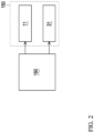
- a flat knitting machine 100 mainly includes needle beds 110, carriages 120, yarn path rails 130, loop pressor beds 140, drive mechanisms 150, and a control unit 160.
- a pair of front and back carriages 120 are disposed to face the front and back needle beds 110 from above.
- the front and back carriages 120 are coupled by a bridge 120a disposed to straddle the plurality of yarn path rails 130.
- the carriage 120 can reciprocate along the longitudinal direction of the needle bed 110 by a servo motor (not illustrated).
- the carriage 120 is provided with a needle selecting mechanism (not illustrated) and a cam mechanism (not illustrated) for selectively operating the knitting needles 111 of the needle bed 110.
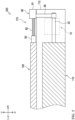
- FIG. 3 and FIG. 5 hatching is applied to the needle bed 110 and the loop pressor bed 140 in order to clarify each member.
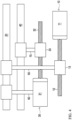
- the drive mechanism 150 moves the needle bed 110 and the loop pressor bed 140 in the longitudinal direction.
- one drive mechanism 150 is provided for the needle bed 110 and the loop pressor bed 140 on the front side
- one drive mechanism 150 is provided for the needle bed 110 and the loop pressor bed 140 on the back side.
- the drive mechanism 150 mainly includes a first drive source 10, a first sliding plate 20, a second drive source 30, and a second sliding plate 40.
- the second sliding plate 40 is a longitudinal platelike member, and is provided so as to extend along the body bed 112 of the needle bed 110 with the longitudinal direction of the second sliding plate 40 oriented in the longitudinal direction of the needle bed 110.
- the second sliding plate 40 is provided above the first sliding plate 20.
- One end of the second sliding plate 40 is coupled to one end (right end in FIG. 3 ) of the loop pressor bed 140 via an appropriate member.
- the nut 33 screwed into the ball screw 32 of the second drive source 30 is coupled to a middle portion of the second sliding plate 40 in the longitudinal direction via an intermediate member 70.
- the control unit 160 drives the first drive motor 11 of the first drive source 10
- the rotational motion of the ball screw 12 is converted into linear motion
- the first sliding plate 20 coupled to the ball screw 12 moves in the left-right direction.
- the needle bed 110 moves in the left-right direction
- the housing coupled to the first sliding plate 20 and the second drive source 30 accommodated in the housing move in the left-right direction.
- the second sliding plate 40 coupled to the second drive source 30 moves in the left-right direction
- the loop pressor bed 140 moves in the left-right direction.
- control unit 160 drives the second drive motor 31 of the second drive source 30
- the rotational motion of the ball screw 32 is converted into linear motion, and the second sliding plate 40 coupled to the ball screw 32 moves in the left-right direction.
- the loop pressor bed 140 moves in the left-right direction.
- the loop pressor bed 140 can be moved relative to the needle bed 110.
- the control unit 160 can selectively drive the first drive source 10 and the second drive source 30 based on the knitting program.
- control unit 160 can move the loop pressor bed 140 integrally with the needle bed 110 without driving the second drive source 30.
- the control unit 160 By integrally moving the loop pressor bed 140 and the needle bed 110, the influence of the difference in responsiveness and the error in the stop position can be reduced. Therefore, it is possible to avoid the loop pressor 141 from colliding with other members such as the movable sinker.
- control unit 160 can adjust the relative position of the loop pressor bed 140 with respect to the needle bed 110 by driving the second drive source 30.
- the loop pressor 141 that has advanced to the needle bed gap S side from interfering with a member such as the movable sinker provided on the needle bed 110 on the opposing side.
- the front and back loop pressors 141 are at positions facing each other and only the loop pressor 141 on one side can advance, or there is a case where the loop pressor 141 is at a position facing the movable sinker on the opposing side and when the loop pressor 141 is advanced to the needle bed gap S side, the loop pressor 141 interferes with the movable sinker on the opposing side.
- the loop pressor 141 can be advanced to the needle bed gap S side without interfering with other members.
- control unit 160 drives the first drive source 10 to move the loop pressor bed 140 integrally with the needle bed 110.
- control unit 160 can relatively move the loop pressor bed 140 with respect to the needle bed 110 by driving the second drive source 80.
- the bed-like member of the disclosure is the loop pressor bed 140, but the disclosure is not limited thereto.
- the bed-like member may be a transfer jack bed provided with a transfer jack for transfer between the front and back needle beds 110.
- the knitting needle 111 is a latch needle
- the knitting needle 111 on the opposing side is inserted between the transfer clip (thin plates) provided on one side of the needle main body and the needle main body to perform transfer, but the knitting needle 111 is disposed in a state of being slightly shifted from the center between the sinkers by the transfer clip. Therefore, the formed stitches are not symmetrical.
- the sinker bed can be relatively moved such that the knitting needle 111 is located at the center between the sinkers.
- the left and right uniform stitches can be formed.
- the range in which the loop pressor bed 140 is relatively movable with respect to the needle bed 110 is set to be within 1 pitch, but any value can be set according to the type of the bed-like member of the disclosure.
- the range in which the bed-like member is relatively movable with respect to the needle bed 110 may be set to be smaller than the range in which the needle bed 110 is relatively movable.
Landscapes
- Engineering & Computer Science (AREA)
- Textile Engineering (AREA)
- Knitting Machines (AREA)
Applications Claiming Priority (1)
| Application Number | Priority Date | Filing Date | Title |
|---|---|---|---|
| JP2023090048A JP2024172375A (ja) | 2023-05-31 | 2023-05-31 | 横編機 |
Publications (1)
| Publication Number | Publication Date |
|---|---|
| EP4471201A1 true EP4471201A1 (fr) | 2024-12-04 |
Family
ID=91247250
Family Applications (1)
| Application Number | Title | Priority Date | Filing Date |
|---|---|---|---|
| EP24177608.7A Pending EP4471201A1 (fr) | 2023-05-31 | 2024-05-23 | Machine à tricoter rectiligne |
Country Status (3)
| Country | Link |
|---|---|
| EP (1) | EP4471201A1 (fr) |
| JP (1) | JP2024172375A (fr) |
| CN (1) | CN119061570A (fr) |
Citations (4)
| Publication number | Priority date | Publication date | Assignee | Title |
|---|---|---|---|---|
| DE1785469A1 (de) * | 1967-09-27 | 1972-02-03 | Courtaulds Ltd | Verfahren zum Wirken von Jersey,sowie Vorrichtung zur Durchfuehrung dieses Verfahrens |
| US5884505A (en) * | 1997-09-12 | 1999-03-23 | Shima Seiki Manufacturing, Ltd. | Flat knitting machine with loop pressers and a knitting method with the flat knitting machine |
| US5992184A (en) * | 1997-12-19 | 1999-11-30 | Shima Seiki Mfg., Ltd. | Flat knitting machine having a transfer jack transferring mechanism |
| CN105133168A (zh) * | 2014-06-09 | 2015-12-09 | 冯加林 | 一种横编织机 |
Family Cites Families (2)
| Publication number | Priority date | Publication date | Assignee | Title |
|---|---|---|---|---|
| JP5079682B2 (ja) * | 2008-12-29 | 2012-11-21 | 株式会社島精機製作所 | 筒状編地編成用横編機および筒状編地の編成方法 |
| JP5955180B2 (ja) * | 2012-09-24 | 2016-07-20 | 株式会社島精機製作所 | ステッチプレッサを備えた横編機及びその制御方法 |
-
2023
- 2023-05-31 JP JP2023090048A patent/JP2024172375A/ja active Pending
-
2024
- 2024-05-23 EP EP24177608.7A patent/EP4471201A1/fr active Pending
- 2024-05-24 CN CN202410652196.6A patent/CN119061570A/zh active Pending
Patent Citations (5)
| Publication number | Priority date | Publication date | Assignee | Title |
|---|---|---|---|---|
| DE1785469A1 (de) * | 1967-09-27 | 1972-02-03 | Courtaulds Ltd | Verfahren zum Wirken von Jersey,sowie Vorrichtung zur Durchfuehrung dieses Verfahrens |
| US5884505A (en) * | 1997-09-12 | 1999-03-23 | Shima Seiki Manufacturing, Ltd. | Flat knitting machine with loop pressers and a knitting method with the flat knitting machine |
| JP3044373B2 (ja) | 1997-09-12 | 2000-05-22 | 株式会社島精機製作所 | ループプレッサーを備えた横編機およびループプレッサーを用いた編地編成方法 |
| US5992184A (en) * | 1997-12-19 | 1999-11-30 | Shima Seiki Mfg., Ltd. | Flat knitting machine having a transfer jack transferring mechanism |
| CN105133168A (zh) * | 2014-06-09 | 2015-12-09 | 冯加林 | 一种横编织机 |
Also Published As
| Publication number | Publication date |
|---|---|
| JP2024172375A (ja) | 2024-12-12 |
| CN119061570A (zh) | 2024-12-03 |
Similar Documents
| Publication | Publication Date | Title |
|---|---|---|
| EP0415512B1 (fr) | Dispositif à dessin pour des métiers à tricoter rectilignes | |
| JP3899269B2 (ja) | 横編機の給糸装置 | |
| KR101329211B1 (ko) | 횡편기 | |
| EP0597548B1 (fr) | Dispositif presse-maille pour métier à tricoter rectiligne | |
| CN114182422A (zh) | 一种针织手套机前后机头同步吃纱同步编织机构及其编织方法 | |
| KR20080081149A (ko) | 횡편기의 선침장치 | |
| JPS62125053A (ja) | 横編機 | |
| EP4471201A1 (fr) | Machine à tricoter rectiligne | |
| EP3636814B1 (fr) | Métier à tricoter rectiligne avec un dispositif guide fils | |
| CN110678593B (zh) | 横机中的添纱编织方法 | |
| EP1514963B1 (fr) | Metier a mailles cueillies presentant un dispositif de platine d'abattage mobile | |
| US7152435B2 (en) | Weft knitting machine having movable sinker | |
| CN100503927C (zh) | 横机、编织方法以及编织程序的生成装置 | |
| KR20040101504A (ko) | 횡편기에 있어서의 자력식 선침장치(磁力式 選針裝置) | |
| EP2789718B1 (fr) | Machine à tricoter à plateau équipé d'une platine mobile | |
| JP2020133010A (ja) | 給糸位置が変更可能な横編機用給糸器 | |
| JP4163085B2 (ja) | 移動体連行状態切換え可能な横編機 | |
| KR200477296Y1 (ko) | 횡편기 | |
| JPH05302249A (ja) | ゲージ可変横編機 | |
| JP7811192B2 (ja) | 横編機 | |
| KR102179409B1 (ko) | 다양한 얀 공급 위치를 갖는 횡편기 얀 공급기 | |
| JP2020133077A (ja) | 歯口隙間の大きさに従って押圧位置が変更する横編機用編地押圧装置 | |
| JP2000314058A (ja) | 横編機における編地の編成方法 | |
| JP2025064273A (ja) | 横編機 | |
| JPH05195392A (ja) | ガルーンクロッシェ編機 |
Legal Events
| Date | Code | Title | Description |
|---|---|---|---|
| PUAI | Public reference made under article 153(3) epc to a published international application that has entered the european phase |
Free format text: ORIGINAL CODE: 0009012 |
|
| STAA | Information on the status of an ep patent application or granted ep patent |
Free format text: STATUS: THE APPLICATION HAS BEEN PUBLISHED |
|
| AK | Designated contracting states |
Kind code of ref document: A1 Designated state(s): AL AT BE BG CH CY CZ DE DK EE ES FI FR GB GR HR HU IE IS IT LI LT LU LV MC ME MK MT NL NO PL PT RO RS SE SI SK SM TR |
|
| STAA | Information on the status of an ep patent application or granted ep patent |
Free format text: STATUS: REQUEST FOR EXAMINATION WAS MADE |
|
| 17P | Request for examination filed |
Effective date: 20250604 |