EP4471358A2 - Installation de pompe à chaleur et procédé de fonctionnement d'une installation de pompe à chaleur - Google Patents
Installation de pompe à chaleur et procédé de fonctionnement d'une installation de pompe à chaleur Download PDFInfo
- Publication number
- EP4471358A2 EP4471358A2 EP24206787.4A EP24206787A EP4471358A2 EP 4471358 A2 EP4471358 A2 EP 4471358A2 EP 24206787 A EP24206787 A EP 24206787A EP 4471358 A2 EP4471358 A2 EP 4471358A2
- Authority
- EP
- European Patent Office
- Prior art keywords
- heat pump
- circuit
- consumer
- transfer medium
- buffer storage
- Prior art date
- Legal status (The legal status is an assumption and is not a legal conclusion. Google has not performed a legal analysis and makes no representation as to the accuracy of the status listed.)
- Granted
Links
Images

Classifications
-
- F—MECHANICAL ENGINEERING; LIGHTING; HEATING; WEAPONS; BLASTING
- F25—REFRIGERATION OR COOLING; COMBINED HEATING AND REFRIGERATION SYSTEMS; HEAT PUMP SYSTEMS; MANUFACTURE OR STORAGE OF ICE; LIQUEFACTION SOLIDIFICATION OF GASES
- F25B—REFRIGERATION MACHINES, PLANTS OR SYSTEMS; COMBINED HEATING AND REFRIGERATION SYSTEMS; HEAT PUMP SYSTEMS
- F25B30/00—Heat pumps
-
- F—MECHANICAL ENGINEERING; LIGHTING; HEATING; WEAPONS; BLASTING
- F24—HEATING; RANGES; VENTILATING
- F24D—DOMESTIC- OR SPACE-HEATING SYSTEMS, e.g. CENTRAL HEATING SYSTEMS; DOMESTIC HOT-WATER SUPPLY SYSTEMS; ELEMENTS OR COMPONENTS THEREFOR
- F24D19/00—Details
- F24D19/08—Arrangements for drainage, venting or aerating
- F24D19/082—Arrangements for drainage, venting or aerating for water heating systems
- F24D19/083—Venting arrangements
-
- F—MECHANICAL ENGINEERING; LIGHTING; HEATING; WEAPONS; BLASTING
- F24—HEATING; RANGES; VENTILATING
- F24D—DOMESTIC- OR SPACE-HEATING SYSTEMS, e.g. CENTRAL HEATING SYSTEMS; DOMESTIC HOT-WATER SUPPLY SYSTEMS; ELEMENTS OR COMPONENTS THEREFOR
- F24D19/00—Details
- F24D19/10—Arrangement or mounting of control or safety devices
- F24D19/1006—Arrangement or mounting of control or safety devices for water heating systems
- F24D19/1009—Arrangement or mounting of control or safety devices for water heating systems for central heating
-
- F—MECHANICAL ENGINEERING; LIGHTING; HEATING; WEAPONS; BLASTING
- F24—HEATING; RANGES; VENTILATING
- F24D—DOMESTIC- OR SPACE-HEATING SYSTEMS, e.g. CENTRAL HEATING SYSTEMS; DOMESTIC HOT-WATER SUPPLY SYSTEMS; ELEMENTS OR COMPONENTS THEREFOR
- F24D3/00—Hot-water central heating systems
- F24D3/10—Feed-line arrangements, e.g. providing for heat-accumulator tanks, expansion tanks ; Hydraulic components of a central heating system
- F24D3/1008—Feed-line arrangements, e.g. providing for heat-accumulator tanks, expansion tanks ; Hydraulic components of a central heating system expansion tanks
-
- F—MECHANICAL ENGINEERING; LIGHTING; HEATING; WEAPONS; BLASTING
- F24—HEATING; RANGES; VENTILATING
- F24D—DOMESTIC- OR SPACE-HEATING SYSTEMS, e.g. CENTRAL HEATING SYSTEMS; DOMESTIC HOT-WATER SUPPLY SYSTEMS; ELEMENTS OR COMPONENTS THEREFOR
- F24D3/00—Hot-water central heating systems
- F24D3/18—Hot-water central heating systems using heat pumps
-
- F—MECHANICAL ENGINEERING; LIGHTING; HEATING; WEAPONS; BLASTING
- F24—HEATING; RANGES; VENTILATING
- F24H—FLUID HEATERS, e.g. WATER OR AIR HEATERS, HAVING HEAT-GENERATING MEANS, e.g. HEAT PUMPS, IN GENERAL
- F24H15/00—Control of fluid heaters
- F24H15/10—Control of fluid heaters characterised by the purpose of the control
- F24H15/12—Preventing or detecting fluid leakage
-
- F—MECHANICAL ENGINEERING; LIGHTING; HEATING; WEAPONS; BLASTING
- F24—HEATING; RANGES; VENTILATING
- F24H—FLUID HEATERS, e.g. WATER OR AIR HEATERS, HAVING HEAT-GENERATING MEANS, e.g. HEAT PUMPS, IN GENERAL
- F24H15/00—Control of fluid heaters
- F24H15/30—Control of fluid heaters characterised by control outputs; characterised by the components to be controlled
- F24H15/305—Control of valves
-
- F—MECHANICAL ENGINEERING; LIGHTING; HEATING; WEAPONS; BLASTING
- F24—HEATING; RANGES; VENTILATING
- F24H—FLUID HEATERS, e.g. WATER OR AIR HEATERS, HAVING HEAT-GENERATING MEANS, e.g. HEAT PUMPS, IN GENERAL
- F24H15/00—Control of fluid heaters
- F24H15/30—Control of fluid heaters characterised by control outputs; characterised by the components to be controlled
- F24H15/335—Control of pumps, e.g. on-off control
-
- F—MECHANICAL ENGINEERING; LIGHTING; HEATING; WEAPONS; BLASTING
- F25—REFRIGERATION OR COOLING; COMBINED HEATING AND REFRIGERATION SYSTEMS; HEAT PUMP SYSTEMS; MANUFACTURE OR STORAGE OF ICE; LIQUEFACTION SOLIDIFICATION OF GASES
- F25B—REFRIGERATION MACHINES, PLANTS OR SYSTEMS; COMBINED HEATING AND REFRIGERATION SYSTEMS; HEAT PUMP SYSTEMS
- F25B49/00—Arrangement or mounting of control or safety devices
-
- F—MECHANICAL ENGINEERING; LIGHTING; HEATING; WEAPONS; BLASTING
- F24—HEATING; RANGES; VENTILATING
- F24D—DOMESTIC- OR SPACE-HEATING SYSTEMS, e.g. CENTRAL HEATING SYSTEMS; DOMESTIC HOT-WATER SUPPLY SYSTEMS; ELEMENTS OR COMPONENTS THEREFOR
- F24D2200/00—Heat sources or energy sources
- F24D2200/12—Heat pump
- F24D2200/123—Compression type heat pumps
-
- F—MECHANICAL ENGINEERING; LIGHTING; HEATING; WEAPONS; BLASTING
- F25—REFRIGERATION OR COOLING; COMBINED HEATING AND REFRIGERATION SYSTEMS; HEAT PUMP SYSTEMS; MANUFACTURE OR STORAGE OF ICE; LIQUEFACTION SOLIDIFICATION OF GASES
- F25B—REFRIGERATION MACHINES, PLANTS OR SYSTEMS; COMBINED HEATING AND REFRIGERATION SYSTEMS; HEAT PUMP SYSTEMS
- F25B2500/00—Problems to be solved
- F25B2500/22—Preventing, detecting or repairing leaks of refrigeration fluids
- F25B2500/222—Detecting refrigerant leaks
-
- Y—GENERAL TAGGING OF NEW TECHNOLOGICAL DEVELOPMENTS; GENERAL TAGGING OF CROSS-SECTIONAL TECHNOLOGIES SPANNING OVER SEVERAL SECTIONS OF THE IPC; TECHNICAL SUBJECTS COVERED BY FORMER USPC CROSS-REFERENCE ART COLLECTIONS [XRACs] AND DIGESTS
- Y02—TECHNOLOGIES OR APPLICATIONS FOR MITIGATION OR ADAPTATION AGAINST CLIMATE CHANGE
- Y02B—CLIMATE CHANGE MITIGATION TECHNOLOGIES RELATED TO BUILDINGS, e.g. HOUSING, HOUSE APPLIANCES OR RELATED END-USER APPLICATIONS
- Y02B30/00—Energy efficient heating, ventilation or air conditioning [HVAC]
- Y02B30/12—Hot water central heating systems using heat pumps
Definitions
- the invention relates to a heat pump system and a method for operating such a heat pump system.
- a heat pump system is understood to mean a system that has at least one heat pump and at least one consumer circuit connected to it with at least one consumer.
- a heat and cold carrier hereinafter referred to as the heat transfer medium, circulates in the consumer circuit.
- the system serves to provide heat and/or alternatively cold to at least one consumer.
- Heat pump systems for the preparation of heating water or hot water are often equipped with a hot water tank and a heating buffer tank, hereinafter referred to as buffer tank.
- the buffer tank is part of the consumer circuit and is connected between the heat pump and at least one consumer.
- heat pumps extract heat from the heat sources air/water/ground or other solid, liquid or gaseous media.
- Heat pumps generally have a refrigerant circuit, which has at least two heat exchangers, also known as heat exchangers, which work as evaporators and/or condensers during operation, as well as a compressor and an expansion valve. A refrigerant is fed into the circuit.
- heat pumps prepare cold water for cooling and air conditioning tasks.
- From the EP 3 734 198 A1 is a heat pump system in which a refrigerant separator is integrated in a flow line of a consumer circuit connected to a heat pump. This is a small unit that is installed directly in a pipe through which the heat transfer medium flows in the consumer circuit.
- the refrigerant separator has a special structure with a deflection device so that a gaseous refrigerant contained in the heat transfer medium can be separated from the liquid heat transfer medium. The refrigerant escapes via a vent.
- a heat pump is housed in a sealed housing.
- the interior of the housing is flushed with purge air.
- From the DE 10 2018 127 205 A1 is a heat pump in which the refrigerant is locked in the condenser with the help of valves depending on a detected leak.
- Vents are designed to remove air (gas) from the circuit.
- Air (gas) is always introduced when a consumer circuit is filled with the heat transfer medium. Air leads to poorer heat transfer on the heating and cooling surfaces, causes flow noise, reduces pump performance, reacts with water-carrying parts and leads to corrosion processes.
- Air (gas) exists in two states: dissolved in the heat transfer medium and in the form of free air bubbles. The free air bubbles can be visible or appear as invisible microbubbles. The smaller the air (gas) bubbles are, the more they remain in the flow. Therefore, it is not possible to remove microbubbles using conventional devices (e.g. automatic degassing).
- microbubble separators are installed.
- the resulting EP 3 734 198 A1 known refrigerant separator is such a microbubble separator.
- Microbubble separators regularly have fittings that influence the flow of the heat transfer medium, e.g. swirl or divert it, in order to separate the air (gas).
- they consist of a two-part chamber. In the lower chamber there are stainless steel or plastic nets that swirl the water. This causes microbubbles to break off. They combine on the elements introduced to form larger air bubbles, which then rise and escape via an automatic vent.
- An alternative design variant can be found, for example, in the DE 90 01 647 U1
- the invention is based on the object of improving the technical safety of a heat pump system with a heat pump which is operated with a potentially dangerous refrigerant, such as propane.
- the object is further achieved by a method for operating such a heat pump system.
- a method for operating such a heat pump system can also be transferred to the method.
- the coolant used for the heat pump is a potentially safety-critical and/or toxic coolant, which is, for example, flammable and/or can lead to an explosive mixture if it accumulates in the air.
- Propane or other toxic hydrocarbon compounds such as butane, isobutane or ammonia are used as coolants.
- the heat transfer medium which is usually liquid, flows in the consumer circuit, whereby the consumer circuit is connected to at least one heat pump via a flow line and a return line.
- the consumer circuit is therefore a closed system.
- Water is typically used as the heat transfer medium.
- the invention provides a (gas) sensor with which a gaseous coolant contained in the consumer circuit is detected and measured.
- the threshold value above which the safety measure is initiated is chosen in such a way that critical accumulation is avoided.
- the threshold value can be set to zero, so that the safety measure is triggered as soon as the sensor measures refrigerant.
- the threshold value is higher so that a certain proportion of refrigerant in the heat transfer medium is tolerated before the safety measure is initiated.
- the sensor system i.e. the sensor in particular in conjunction with the control device, is therefore designed in two stages. In the first stage, the amount of refrigerant is measured and preferably displayed. In the second stage, once the threshold value is reached (which in particular leads to a potentially critical situation, e.g. risk of explosion), the safety measure is initiated.
- the gas sensor is arranged in the consumer circuit.
- the gas sensor is connected to a (primary) component of the consumer circuit, through which the heat transfer medium flows, or at least to a (secondary) component, specifically a pipe such as a vent line, which is in flow connection with a (primary) component.
- the gas sensor generally detects a refrigerant contained in the heat transfer medium of the consumer circuit.
- the refrigerant in the heat transfer medium or a portion that evaporates from the heat transfer medium is therefore detected directly and not, for example, first a refrigerant concentration in a room into which it has escaped, for example via an installed vent.
- the threshold value at which the safety measure is initiated is, for example, a predetermined maximum permissible enrichment (for example in ppm) of the refrigerant within a gas volume or within a gas stream flowing past the gas sensor.
- the safety measure is a warning message so that, for example, operating personnel can intervene (manually).
- the operation of the heat pump system is intervened in automatically and immediately, without manual intervention being necessary.
- a consumer is generally understood to mean a heat exchanger through which the heat transfer medium flows and which transfers the heat/cold of the heat transfer medium to a room, for example a living room or office.
- the consumer is a radiator and the heat transfer medium is preferably heating water.
- the consumer circuit can also have several sub-circuits (secondary circuits), whereby one or more consumers can be arranged in each sub-circuit.
- the consumers are, for example, radiators, surface heating or fan convectors.
- a buffer storage tank is arranged in the consumer circuit, in particular as a heating buffer, which is connected to the heat pump on the inlet side via a supply line and to at least one consumer on the outlet side via a discharge line.
- a heating buffer which is connected to the heat pump on the inlet side via a supply line and to at least one consumer on the outlet side via a discharge line.
- the heat transfer medium flows directly through the buffer storage tank and thus fills its storage volume.
- the heat transfer medium is not, for example, led through heat exchangers contained in the buffer storage tank.
- the buffer storage tank preferably has no heat exchangers.
- the heat transfer fluid typically flows through it from top to bottom.
- there is also no extraction line for extracting hot water and a fresh water supply to replace the extracted water as is the case with a domestic water storage tank.
- the buffer storage is preferably connected in series between the heat pump and the consumers and is usually completely or almost completely filled with the heat transfer medium during operation. In principle, a parallel arrangement (parallel buffer storage) is also possible.
- a buffer storage is basically known and is used for various purposes, for example to optimize the running or operating times of the heat pump, to bridge blocking times or for so-called load management.
- Such buffer storages generally have a volume that depends on the application and the system output. However, the volume is usually at least 50 dm 3 , or at least 100 dm 3 or at least several 100 dm 3 and sometimes even over 1000 dm 3 .
- the buffer storage typically has a volume, for example, in the range of 10-50 dm 3 /kW and in particular in the range of 20-40 dm 3 /kW of the maximum heating output of the heat pump (maximum rated output of the heat pump).
- the buffer tank is usually a cylindrical container with a typically dome-shaped base and lid. There are typically no internals inside the buffer tank to direct the flow of the heat transfer medium, especially no internals that could lead to the outgassing of gas components, as is the case with micro gas separators, for example.
- the buffer tank is also designed as a gas separator.
- a vent line is connected to the buffer tank for this purpose, through which the separated gas and thus possibly also the gaseous refrigerant can escape.
- the buffer tank preferably has no built-in elements for flow control. Rather, the actual function of the buffer tank in the sense of a large storage volume is used, which means that the heat transfer medium remains within the buffer tank for a sufficiently long time so that gas components contained in the heat transfer medium can outgas and accumulate in an upper area of the buffer tank or can escape the buffer tank via the vent line preferably connected there.
- the buffer tank is therefore typically in operation up to a Filling level is filled with the heat transfer medium, whereby a free gas space is usually formed above the filling level.
- the buffer tank is therefore generally designed and particularly dimensioned in such a way that any gas bubbles contained in the heat transfer medium can rise upwards during operation and collect in the upper area of the buffer tank and/or leave the buffer tank via the vent line.
- the volume and geometry are selected in particular depending on an expected maximum volume flow of the heat transfer medium in such a way that the flow velocity in the buffer tank is sufficiently low so that gas bubbles can rise and reach the highest point of the buffer tank and the vent line.
- the particular advantage of using the buffer storage as a gas separator is its high efficiency. It can also be used to separate gas components that cannot be separated with conventional micro gas separators, as these usually do not have a 100% separation efficiency.
- the heat transfer medium flows through the buffer storage tank during operation from above, i.e. from the supply line downwards, i.e. towards the discharge line.
- the supply line is arranged in an upper area and the discharge line in a lower area. Typically, these are arranged in the top or bottom fifth of the storage volume.
- the buffer storage is now preferably dimensioned in such a way that during operation the flow rate of the heat transfer medium does not exceed a specified maximum limit value, which is in the range of 0.1 m/s to 0.3 m/s.
- the consumer circuit with the supply and discharge lines to/from the buffer storage is usually designed for a maximum volume flow of the heat transfer medium, which is therefore circulated in the consumer circuit at maximum heating output, for example.
- the geometry, i.e. the volume and the cross-sectional area (diameter) of the buffer storage is selected in such a way that the flow rate does not exceed the specified values. This ensures a comparatively low flow rate overall.
- the diameter is typically greater than 0.5 m and depends on the size of the system.
- the height is typically a multiple of the diameter, for example 3 to 6 times.
- This design of the buffer storage is based on the idea of setting the (maximum) flow rate of the heat transfer medium within the buffer storage so that it is lower than the ascent rate of the gas bubbles contained therein. This ensures that the gas bubbles reach the highest point and can leave the buffer storage there.
- gas bubbles can move in the earth's gravitational field due to a density difference between two phases or in a flow field with forced convection.
- the decisive factor for the function of the separation and the quality of the separation is the reduction of the flow velocity from that in the supply line to the buffer storage, which is often around 1.5 m/s, to a lower velocity in the buffer storage.
- the senor is arranged and designed in such a way that it detects the gaseous refrigerant separated in the buffer tank.
- the sensor is connected to the upper area of the buffer tank, for example arranged directly there.
- it is arranged in the vent line, so it measures the proportion of refrigerant within the gas flow that escapes via the vent line.
- the senor can also be arranged at a different position within the consumer circuit, for example in the area of the heat pump.
- the sensor can also measure a coolant contained in a gas flow, with the gas flow escaping via a micro air separator or another vent.
- an automatic vent valve is preferably provided, which is specially designed as a so-called (quick) vent.
- This vent valve is connected to the vent line so that the gas accumulated in the buffer tank can automatically escape into the vent line via the vent valve.
- the valve opens automatically when gas accumulates at the vent valve.
- the senor is arranged downstream of this vent valve and therefore measures the proportion of refrigerant in the gas flow discharged via the vent line.
- the ventilation line is led through a building wall into a safety area and ends there.
- the safety area is in particular an outdoor area outside the building in which the buffer storage is located. This prevents the coolant from accumulating in the room in which the buffer storage is located.
- a micro gas separator is arranged in the consumer circuit. This is installed directly in the piping, for example in the flow line, specifically directly on the heat pump. The heat transfer medium therefore flows through it during operation. It has built-in components designed to separate gaseous components from the heat transfer medium.
- This micro gas separator is a gas separator known per se, as described at the beginning. This micro gas separator is preferably installed between the heat pump and the buffer tank in the flow line.
- the micro gas separator is preferably installed in a safety area, particularly an outdoor area outside the building.
- the rest of the consumer circuit is located inside the building. This also ensures that coolant cannot accumulate inside the building.
- the safety area can also be a hall or other operating room, particularly if it is sufficiently ventilated, for example.
- control device is designed such that the supply of the at least one consumer with the heat transfer medium is prevented as a safety measure.
- the at least one and preferably all consumers are therefore virtually switched off, so that the heat transfer medium no longer circulates through the consumer(s) and no coolant can escape via the consumer, for example via a vent arranged on the consumer.
- the consumer circuit is preferably divided into a primary circuit and at least one secondary circuit connected to the primary circuit, in which the at least one consumer is integrated. All consumers are arranged in the at least one secondary circuit.
- the primary circuit can also be viewed as an intermediate circuit which is arranged between the heat pump and the secondary circuit. The primary circuit is therefore directly connected to the heat pump.
- the buffer storage is also arranged in the primary circuit.
- the heat transfer medium can circulate in the respective circuit at least in a special operating mode of the heat pump system.
- the secondary circuit can be hydraulically coupled or decoupled from the primary circuit via a controllable shut-off valve, such as a shut-off valve or a flap, and the control device is further designed in such a way that the shut-off valve is closed as part of the safety measure.
- a controllable shut-off valve such as a shut-off valve or a flap
- the control device is further designed in such a way that the shut-off valve is closed as part of the safety measure.
- the secondary circuit and primary circuit are hydraulically connected to one another, i.e. the heat transfer medium flows through both of them.
- a secondary (circulation) pump is arranged in at least one secondary circuit.
- this is preferably switched off. Both of these measures ensure that the heat transfer medium is no longer circulated in the secondary circuit.
- this secondary pump In normal operation, i.e. in which no safety measure is activated, this secondary pump is in operation and preferably as the main pump to circulate the heat transfer medium in the consumer circuit.
- the safety measure involves switching from a normal operating mode to a degassing mode in which the proportion of coolant in the heat transfer medium is reduced by removing the coolant from the heat transfer medium.
- the removal takes place, for example, via the buffer storage designed as a gas separator and/or with the help of the micro gas separator.
- circulation mode is preferably provided in which the heat transfer medium is only circulated in the primary circuit and thus without involving the consumer(s).
- This circulation mode supports the desired degassing via the buffer tank and/or the micro gas separator.
- the heat transfer medium is therefore preferably passed through the buffer tank.
- a primary pump is arranged in the primary circuit, so that in the preferred embodiment at least one pump is arranged in both the primary circuit and the secondary circuit.
- the primary pump in the primary circuit is in operation both in the normal operating mode and in the degassing mode.
- control device is set up in such a way that when the refrigerant detected by the sensor falls below a lower threshold value, the system switches from degassing mode back to normal operating mode. This preferably takes place automatically depending on the sensor's measurement result, without manual action by operating personnel being required. Alternatively, switching to normal operating mode is only possible manually, e.g. by service personnel and, for example, after a fault message has been rectified or after a service call.
- the consumer circuit generally has a supply line and a return line.
- these two lines can be hydraulically connected to one another via a lockable connecting line.
- This hydraulic connection is opened especially in degassing mode and thus as part of the safety measure, so that the supply line is virtually short-circuited with the return line and the heat transfer medium can be circulated (exclusively) in the primary circuit.
- This connecting line therefore closes the primary circuit without the secondary circuit.
- the connecting line is arranged - viewed in the flow direction in the supply line - before and thus upstream of at least one secondary circuit.
- the shut-off valve arranged in the supply line for shutting off the secondary circuit is arranged downstream of and thus downstream of the branch of the connecting line in the supply line.
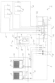
- Figure 1 shows a heat pump system 2 with at least one heat pump 4, in which a consumer circuit 6 is included.
- a consumer circuit 6 in which a consumer circuit 6 is included.
- the consumer circuit 6 can be divided into a primary circuit 8 and at least one secondary circuit 10, preferably several, in the exemplary embodiment two secondary circuits 10, which are connected to the primary circuit 8.
- Each secondary circuit 10 has at least one consumer 12.
- the consumers 12 each serve to transfer heat (and/or cold) into a room to be heated (cooled) or a process.
- a buffer storage tank 14 is also arranged in the primary circuit 8. During operation, a heat transfer medium is fed to this in an upper area via a supply line 16. After flowing through the buffer storage tank 14, the heat transfer medium leaves it in a lower area via a discharge line 18. The secondary circuits 10 are supplied with the heat transfer medium via the discharge line 18.
- the buffer storage tank 14 is generally connected to a supply line 20. The heat transfer medium flows via this from the respective heat pump 4 first to the buffer storage tank 14 and from there into the secondary circuits 10 to the consumers 12. The heat transfer medium is returned to the heat pumps 4 via a return line 22.
- Each heat pump 4 is designed as a conventional heat pump known per se and has a refrigerant circuit not shown in detail here. As usual, this circuit comprises a compressor, an expansion valve and two heat exchangers that operate as condensers and/or evaporators.
- the heat pumps 4 are air-water heat pumps that exchange heat/cold with the ambient air in an outdoor installation via one heat exchanger.
- a coolant in particular a potentially dangerous/toxic coolant such as propane, is circulated in the coolant circuit. Heat/cold is transferred to the heat transfer medium via the second heat exchanger.
- the two heat pumps 4 are located outdoors, i.e. outside a building 24 and thus in a safety area 26.
- the building 24 is only partially shown here by a building wall. With the exception of the two heat pumps 4 installed outdoors, all components of the heat pump system 2 are located inside the building 24.
- the building 24 is, for example, a residential building, an office building, etc.
- the heat pump system 2 is generally used in particular for heating/cooling the building 24.
- the heat pump system 2 has a first hydraulic module 28 and a second hydraulic module 30.
- various units such as pumps and valves are arranged, via which the circulation of the heat transfer medium in the consumer circuit 6 is controlled.
- control device 32 This is connected to the individual components via control lines 31 and, if required, via wireless communication connections.
- micro gas separators 33 are arranged in the exemplary embodiment, which are connected in the flow line directly downstream of a respective heat pump 4.
- the micro gas separators 33 already separate the gas components contained in the heat transfer medium.
- the micro gas separators 33 are arranged in the safety area 26, i.e. in particular in the outdoor area, so that the gas discharged via them escapes into the environment.
- vent valves or other valves/vents are arranged within the building 24, at least in the entire primary circuit 8, through which gas and thus coolant could escape from the consumer circuit 6 and enter the building. Any vent valves that may be present release the gas into the safety area 26.
- vents are arranged on the consumers 12, for example.
- the primary circuit 10 is usually protected against pressure excess by at least one safety valve. This is located in the safety area 26 or vents there.
- a vent line 34 is connected to the top point of the buffer tank 14.
- a shut-off valve is shown immediately following the top point of the buffer tank 14, but this is not absolutely necessary.
- a vent valve 36 is connected to the vent line 34. This opens automatically when gas is present in the upper area of the buffer tank 14, so that it can be discharged via the vent line 34.
- the vent valve 36 could also be installed directly at the top point of the buffer tank 14. It is important that the gas is released from the vent valve 36 into the vent line 34.
- the vent line 34 leads in particular into the safety area 26, i.e. specifically to the outside, so that the gas is released to the outside.
- a (gas) sensor 38 is also connected to the vent line 34, which is designed to detect any (gaseous) refrigerant that may be present.
- shut-off valves that serve to shut off the inlet line 16 or the outlet line 18, and in the exemplary embodiment, electrical heating rods that are switched on as additional heating when required.
- insulation is indicated that regularly surrounds the buffer tank 14.
- the buffer tank 14 is designed in such a way that it acts as a gas separator.
- it is designed in such a way that a maximum flow speed of the heat transfer medium flowing from top to bottom does not exceed a predetermined value, which is in particular between 0.1-0.3 m/s. This value is selected in such a way that the ascending speed of bubbles contained in the heat transfer medium is greater than the flow speed of the heat transfer medium, so that the bubbles migrate to the upper area of the buffer tank 14 and can cause this via the vent line 34.
- sensor 38 detects refrigerant or a critical value for the refrigerant, i.e. if the measured value exceeds a threshold value, a safety measure is generally initiated.
- the measured value recorded by the sensor 38 is evaluated and suitable components are controlled.
- the evaluation and control can already be integrated in the sensor 38, which in this case is therefore designed as a combined sensor and control unit.
- the measured value is transmitted to a separate control unit, for example the control device 32, which then initiates the appropriate measures.
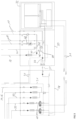
- the security measures introduced are in connection with the Figure 1 and in particular with reference to the enlarged representation according to the Figure 3 explained in more detail:
- the first hydraulic module 28 is connected to the supply lines 20 and return lines 22 coming from the heat pumps 4.
- the supply lines 20 are connected to one another and open into the supply line 16.
- a primary pump 40 is arranged for each heat pump 4, which in the exemplary embodiment are connected in the return line 22 of the respective heat pump 4.
- the flow direction of the heat transfer medium is indicated in the figures by arrows.
- the second hydraulic module 30 is initially connected on the input side to the discharge line 18 (coming from the buffer tank).
- the two secondary circuits 10 are connected to this, i.e. a respective flow of the respective secondary circuit 10 branches off.
- a motor-driven and controllable shut-off valve 42 is arranged in the flow between the discharge line 18 and the secondary circuits 10, i.e. between the primary circuit 8 and the secondary circuits 10.
- the two secondary circuits 10 each have a return line, which is connected to the return line 22 of the primary circuit 8.
- a shut-off valve 42 is also arranged in this return line.
- the flow line 20 is fluidically connected to the return line 22 via a connecting line 44.
- a further shut-off valve in particular in the form of a non-return valve 46, is arranged in the connecting line 44.
- a secondary pump 48 is also arranged in the respective flow line, which serves to circulate the heat transfer medium in the respective secondary circuit 10.
- the return line 22 connects the two hydraulic modules 28, 30, with a detachable connection 50 being provided specifically for this purpose.
- a detachable connection 50 being provided specifically for this purpose.
- one of the control lines 31 is led from the control device 32 to the first hydraulic module 28, which can also be separated via a detachable plug connection.
- the following measures are preferably taken:
- the circulation of the heat transfer medium in the secondary circuits 10 is prevented, so that no coolant can escape into the individual rooms, for example via the vents often arranged on the consumers 12.
- the two shut-off valves 42 are closed and at the same time the secondary pumps 48 are also switched off.
- the secondary circuits 10 are thus separated from the rest of the consumer circuit 6 and especially from the primary circuit 8.
- a degassing mode is also provided in which the proportion of coolant in the heat transfer medium is reduced.
- a circulation operation of the heat transfer medium in the primary circuit 8 is provided in particular.
- the additional shut-off valve 46 is opened, or the additional shut-off valve 46 (check valve) opens automatically so that the heat transfer medium can circulate in the primary circuit 8 while decoupling the secondary circuits 10.
- the heat transfer medium is circulated using the primary pumps 40.
- the buffer storage 14 is therefore still operated in its capacity as a gas separator according to a first variant, so that gas contained in the heat transfer medium and thus also the gaseous refrigerant can escape.
- the buffer tank 14 is used to separate gas components in particular which are not separated by the additionally provided micro gas separators 33.
- the vent line 34 is closed and the gaseous coolant is removed via the micro gas separator 33.
- the safety concept described here therefore prevents a critical escape of flammable refrigerant. This is achieved in particular by the fact that in the event of a leak in the heat exchangers, the refrigerant that has penetrated into the consumer circuit 6 is collected in a controlled manner in the buffer tank 14 and safely discharged.
- the improved safety compared to conventional systems is achieved by the (additional) installation of safety components and by changing the control and regulation concept.
Landscapes
- Engineering & Computer Science (AREA)
- Physics & Mathematics (AREA)
- Thermal Sciences (AREA)
- Mechanical Engineering (AREA)
- General Engineering & Computer Science (AREA)
- Chemical & Material Sciences (AREA)
- Combustion & Propulsion (AREA)
- Other Air-Conditioning Systems (AREA)
- Air Conditioning Control Device (AREA)
- Compression-Type Refrigeration Machines With Reversible Cycles (AREA)
Applications Claiming Priority (2)
| Application Number | Priority Date | Filing Date | Title |
|---|---|---|---|
| DE102021201712.6A DE102021201712A1 (de) | 2021-02-23 | 2021-02-23 | Wärmepumpenanlage sowie Verfahren zum Betreiben einer Wärmepumpenanlage |
| EP22156476.8A EP4047275B1 (fr) | 2021-02-23 | 2022-02-14 | Installation de pompe à chaleur, ainsi que procédé de fonctionnement d'une installation de pompe à chaleur |
Related Parent Applications (1)
| Application Number | Title | Priority Date | Filing Date |
|---|---|---|---|
| EP22156476.8A Division EP4047275B1 (fr) | 2021-02-23 | 2022-02-14 | Installation de pompe à chaleur, ainsi que procédé de fonctionnement d'une installation de pompe à chaleur |
Publications (3)
| Publication Number | Publication Date |
|---|---|
| EP4471358A2 true EP4471358A2 (fr) | 2024-12-04 |
| EP4471358A3 EP4471358A3 (fr) | 2025-03-05 |
| EP4471358B1 EP4471358B1 (fr) | 2025-09-03 |
Family
ID=80682432
Family Applications (2)
| Application Number | Title | Priority Date | Filing Date |
|---|---|---|---|
| EP24206787.4A Active EP4471358B1 (fr) | 2021-02-23 | 2022-02-14 | Installation de pompe à chaleur et procédé de fonctionnement d'une installation de pompe à chaleur |
| EP22156476.8A Active EP4047275B1 (fr) | 2021-02-23 | 2022-02-14 | Installation de pompe à chaleur, ainsi que procédé de fonctionnement d'une installation de pompe à chaleur |
Family Applications After (1)
| Application Number | Title | Priority Date | Filing Date |
|---|---|---|---|
| EP22156476.8A Active EP4047275B1 (fr) | 2021-02-23 | 2022-02-14 | Installation de pompe à chaleur, ainsi que procédé de fonctionnement d'une installation de pompe à chaleur |
Country Status (3)
| Country | Link |
|---|---|
| EP (2) | EP4471358B1 (fr) |
| DE (2) | DE102021201712A1 (fr) |
| PL (2) | PL4471358T3 (fr) |
Families Citing this family (16)
| Publication number | Priority date | Publication date | Assignee | Title |
|---|---|---|---|---|
| DE102022201790A1 (de) | 2021-09-30 | 2023-03-30 | ECOOLTEC Grosskopf GmbH | Verfahren und Vorrichtung zum Temperieren eines zu temperierenden Raums |
| JP2024536336A (ja) * | 2021-09-30 | 2024-10-04 | エクールテック・グロスコフ・ゲーエムベーハー | 温度制御される空間を温度制御するための方法および装置 |
| EP4194769B1 (fr) | 2021-12-07 | 2025-08-13 | Glen Dimplex Deutschland GmbH | Installation de réfrigérant et module de réfrigérant |
| SE546745C2 (en) * | 2022-04-26 | 2025-02-18 | Qtf Sweden Ab | A system and method for detecting gas leakage |
| DE102022112153A1 (de) | 2022-05-16 | 2023-11-16 | Vaillant Gmbh | Verfahren zur Entgasung eines Heizkreises, Computerprogramm, Regel- und Steuergerät und Klimagerät |
| DE102022131727A1 (de) | 2022-11-30 | 2024-06-06 | Stiebel Eltron Gmbh & Co. Kg | Wärmepumpensystem mit Gasabscheider |
| DE102022131726A1 (de) | 2022-11-30 | 2024-06-06 | Stiebel Eltron Gmbh & Co. Kg | Wärmepumpensystem mit Gasabscheider |
| EP4421394A1 (fr) * | 2023-02-23 | 2024-08-28 | Daikin Europe N.V. | Unité extérieure |
| DE102023116266A1 (de) | 2023-06-21 | 2024-12-24 | Vaillant Gmbh | Verfahren zur Erkennung von Gas in einem Heizkreis eines Klimagerätes, Computerprogramm, Regel- und Steuergerät und Klimagerät |
| DE102023130322A1 (de) * | 2023-11-02 | 2025-05-08 | Stiebel Eltron Gmbh & Co. Kg | Wärmepumpensystem und zugehöriges Verfahren |
| DE102023133570A1 (de) * | 2023-11-30 | 2025-06-05 | David Schweitzer | Explosionsschutz für eine Zentralheizungsanlage mit einer Wärmepumpe mit einem brennbaren Kältemittel |
| DE102023136093A1 (de) * | 2023-12-20 | 2025-06-26 | Stiebel Eltron Gmbh & Co. Kg | Sicherungsabschaltung für Wärmepumpensystem |
| DE102024201713A1 (de) | 2024-02-23 | 2025-08-28 | Glen Dimplex Deutschland Gmbh | Kältemittelanlage sowie Verfahren zum Betrieb einer Kältemittelanlage |
| NL2037600B1 (en) * | 2024-05-02 | 2025-11-18 | Spiro Entpr Bv | Deaerator for heat pump system |
| DE102024112924A1 (de) * | 2024-05-08 | 2025-11-13 | Viessmann Holding International GmbH | Wärmepumpenanlage, Energietransportsystem und Verfahren zum Überwachen eines Energietransportsystems |
| DE102024126690A1 (de) | 2024-09-17 | 2026-03-19 | Vaillant Gmbh | Entgasungsvorrichtung für einen Flüssigkeitsstrom und HVAC-Anlage |
Citations (4)
| Publication number | Priority date | Publication date | Assignee | Title |
|---|---|---|---|---|
| DE9001647U1 (de) | 1989-04-06 | 1990-04-19 | Flamco B.V., Gouda | Vorrichtung zum Abscheiden von Gas aus einer Flüssigkeit und zum Abführen des freigesetzten Gases |
| DE102018113332A1 (de) | 2018-06-05 | 2019-12-05 | Vaillant Gmbh | Sicherheitsspülvorrichtung für ein Kältekreisgehäuse |
| DE102018127205A1 (de) | 2018-10-31 | 2020-04-30 | Vaillant Gmbh | Sicherheitszone im Kondensator |
| EP3734198A1 (fr) | 2019-04-29 | 2020-11-04 | Wolf GmbH | Dispositif de séparation de réfrigérant pour système de pompe à chaleur et procédé de fonctionnement d'un dispositif de séparation de réfrigérant |
Family Cites Families (5)
| Publication number | Priority date | Publication date | Assignee | Title |
|---|---|---|---|---|
| JP2000104940A (ja) | 1998-09-28 | 2000-04-11 | Kyushu Electric Power Co Inc | ヒートポンプ式給湯システム |
| WO2010109617A1 (fr) * | 2009-03-26 | 2010-09-30 | 三菱電機株式会社 | Appareil de conditionnement d'air |
| JP6545373B2 (ja) * | 2016-05-17 | 2019-07-17 | 三菱電機株式会社 | 空気調和機 |
| WO2018116404A1 (fr) | 2016-12-21 | 2018-06-28 | 三菱電機株式会社 | Équipement d'utilisation de pompe à chaleur |
| DE102019119229A1 (de) * | 2019-07-16 | 2021-01-21 | Vaillant Gmbh | Sicherheitsablass einer Wärmepumpenaußeneinheit |
-
2021
- 2021-02-23 DE DE102021201712.6A patent/DE102021201712A1/de active Pending
-
2022
- 2022-02-14 DE DE202022100810.8U patent/DE202022100810U1/de active Active
- 2022-02-14 EP EP24206787.4A patent/EP4471358B1/fr active Active
- 2022-02-14 EP EP22156476.8A patent/EP4047275B1/fr active Active
- 2022-02-14 PL PL24206787.4T patent/PL4471358T3/pl unknown
- 2022-02-14 PL PL22156476.8T patent/PL4047275T3/pl unknown
Patent Citations (4)
| Publication number | Priority date | Publication date | Assignee | Title |
|---|---|---|---|---|
| DE9001647U1 (de) | 1989-04-06 | 1990-04-19 | Flamco B.V., Gouda | Vorrichtung zum Abscheiden von Gas aus einer Flüssigkeit und zum Abführen des freigesetzten Gases |
| DE102018113332A1 (de) | 2018-06-05 | 2019-12-05 | Vaillant Gmbh | Sicherheitsspülvorrichtung für ein Kältekreisgehäuse |
| DE102018127205A1 (de) | 2018-10-31 | 2020-04-30 | Vaillant Gmbh | Sicherheitszone im Kondensator |
| EP3734198A1 (fr) | 2019-04-29 | 2020-11-04 | Wolf GmbH | Dispositif de séparation de réfrigérant pour système de pompe à chaleur et procédé de fonctionnement d'un dispositif de séparation de réfrigérant |
Also Published As
| Publication number | Publication date |
|---|---|
| PL4047275T3 (pl) | 2025-03-10 |
| DE202022100810U1 (de) | 2022-02-28 |
| EP4047275A1 (fr) | 2022-08-24 |
| EP4471358B1 (fr) | 2025-09-03 |
| DE102021201712A1 (de) | 2022-08-25 |
| EP4047275B1 (fr) | 2024-11-06 |
| EP4471358A3 (fr) | 2025-03-05 |
| PL4471358T3 (pl) | 2026-02-23 |
Similar Documents
| Publication | Publication Date | Title |
|---|---|---|
| EP4047275B1 (fr) | Installation de pompe à chaleur, ainsi que procédé de fonctionnement d'une installation de pompe à chaleur | |
| EP3747532B1 (fr) | Séparateur de gaz à membrane | |
| EP3767186B1 (fr) | Procédé de commande d'une unité extérieure d'une pompe à chaleur | |
| DE102022123440A1 (de) | Serviceanschluss für ein Wärmepumpengehäuse | |
| DE102010003915B4 (de) | Kälteanlage mit Wärmerückgewinnung und Verfahren zum Betreiben der Kälteanlage | |
| EP3789686A1 (fr) | Système de pompe à chaleur | |
| EP4176210A1 (fr) | Dispositif de séparation destiné en particulier à un système de pompe à chaleur | |
| EP4382814A1 (fr) | Dispositif d'écoulement pour l'équipement ultérieur d'une installation de chauffage et installation de chauffage | |
| EP3182813A1 (fr) | Système de refroidissement d'onduleur | |
| DE102007054724B4 (de) | Installationsschrank zur Aufnahme von elektrischen oder elektronischen Geräten, insbesondere von Recheneinrichtungen, sowie Einrichtung aufweisend mehrere solcher Installationsschränke, und Verfahren zum Betreiben einer solchen Einrichtung | |
| DE3039722C2 (fr) | ||
| EP4336108B1 (fr) | Séparation de réfrigérant dans un circuit de chauffage | |
| EP4379267A1 (fr) | Système de pompe à chaleur avec séparateur de gaz | |
| EP3767187B1 (fr) | Procédé de commande d'un ensemble de pompes à chaleur | |
| DE202011102503U1 (de) | Wärmepumpenanlage | |
| AT509723B1 (de) | Frostschutzeinrichtung | |
| DE102021004390A1 (de) | System für eine mit einem flüssigen Kälteträger betriebene Tiefkältekreislaufanlage und Verfahren zum Betreiben eines derartigen Systems | |
| EP4610578A1 (fr) | Siphon avec dispositif de blocage de sécurité | |
| WO2025162750A1 (fr) | Dispositif pour un boîtier de batterie | |
| DE102024104854A1 (de) | Abscheideeinrichtung, insbesondere für eine Wärmepumpe | |
| DE102023119984A1 (de) | Gasleckagebewältigung | |
| EP3516226A1 (fr) | Compresseur à vis pour véhicule utilitaire | |
| EP4378555A1 (fr) | Séparateur destiné à être utilisé dans un système de pompe à chaleur | |
| DE102023136093A1 (de) | Sicherungsabschaltung für Wärmepumpensystem | |
| DE102024201713A1 (de) | Kältemittelanlage sowie Verfahren zum Betrieb einer Kältemittelanlage |
Legal Events
| Date | Code | Title | Description |
|---|---|---|---|
| PUAI | Public reference made under article 153(3) epc to a published international application that has entered the european phase |
Free format text: ORIGINAL CODE: 0009012 |
|
| STAA | Information on the status of an ep patent application or granted ep patent |
Free format text: STATUS: THE APPLICATION HAS BEEN PUBLISHED |
|
| AC | Divisional application: reference to earlier application |
Ref document number: 4047275 Country of ref document: EP Kind code of ref document: P |
|
| AK | Designated contracting states |
Kind code of ref document: A2 Designated state(s): AL AT BE BG CH CY CZ DE DK EE ES FI FR GB GR HR HU IE IS IT LI LT LU LV MC MK MT NL NO PL PT RO RS SE SI SK SM TR |
|
| REG | Reference to a national code |
Ref country code: DE Ref legal event code: R079 Ipc: F24D0003100000 Ref country code: DE Ref legal event code: R079 Ref document number: 502022005363 Country of ref document: DE Free format text: PREVIOUS MAIN CLASS: F25B0049000000 Ipc: F24D0003100000 |
|
| PUAL | Search report despatched |
Free format text: ORIGINAL CODE: 0009013 |
|
| STAA | Information on the status of an ep patent application or granted ep patent |
Free format text: STATUS: REQUEST FOR EXAMINATION WAS MADE |
|
| AK | Designated contracting states |
Kind code of ref document: A3 Designated state(s): AL AT BE BG CH CY CZ DE DK EE ES FI FR GB GR HR HU IE IS IT LI LT LU LV MC MK MT NL NO PL PT RO RS SE SI SK SM TR |
|
| RIC1 | Information provided on ipc code assigned before grant |
Ipc: F25B 49/00 20060101ALI20250130BHEP Ipc: F25B 30/00 20060101ALI20250130BHEP Ipc: F25B 41/39 20210101ALI20250130BHEP Ipc: F24H 15/335 20220101ALI20250130BHEP Ipc: F24H 15/305 20220101ALI20250130BHEP Ipc: F24H 15/12 20220101ALI20250130BHEP Ipc: F24D 19/10 20060101ALI20250130BHEP Ipc: F24D 19/08 20060101ALI20250130BHEP Ipc: F24D 3/18 20060101ALI20250130BHEP Ipc: F24D 3/10 20060101AFI20250130BHEP |
|
| 17P | Request for examination filed |
Effective date: 20250217 |
|
| GRAP | Despatch of communication of intention to grant a patent |
Free format text: ORIGINAL CODE: EPIDOSNIGR1 |
|
| STAA | Information on the status of an ep patent application or granted ep patent |
Free format text: STATUS: GRANT OF PATENT IS INTENDED |
|
| RIC1 | Information provided on ipc code assigned before grant |
Ipc: F25B 49/00 20060101ALI20250410BHEP Ipc: F25B 30/00 20060101ALI20250410BHEP Ipc: F25B 41/39 20210101ALI20250410BHEP Ipc: F24H 15/335 20220101ALI20250410BHEP Ipc: F24H 15/305 20220101ALI20250410BHEP Ipc: F24H 15/12 20220101ALI20250410BHEP Ipc: F24D 19/10 20060101ALI20250410BHEP Ipc: F24D 19/08 20060101ALI20250410BHEP Ipc: F24D 3/18 20060101ALI20250410BHEP Ipc: F24D 3/10 20060101AFI20250410BHEP |
|
| INTG | Intention to grant announced |
Effective date: 20250509 |
|
| GRAS | Grant fee paid |
Free format text: ORIGINAL CODE: EPIDOSNIGR3 |
|
| P01 | Opt-out of the competence of the unified patent court (upc) registered |
Free format text: CASE NUMBER: APP_30349/2025 Effective date: 20250625 |
|
| GRAA | (expected) grant |
Free format text: ORIGINAL CODE: 0009210 |
|
| STAA | Information on the status of an ep patent application or granted ep patent |
Free format text: STATUS: THE PATENT HAS BEEN GRANTED |
|
| AC | Divisional application: reference to earlier application |
Ref document number: 4047275 Country of ref document: EP Kind code of ref document: P |
|
| AK | Designated contracting states |
Kind code of ref document: B1 Designated state(s): AL AT BE BG CH CY CZ DE DK EE ES FI FR GB GR HR HU IE IS IT LI LT LU LV MC MK MT NL NO PL PT RO RS SE SI SK SM TR |
|
| REG | Reference to a national code |
Ref country code: CH Ref legal event code: EP |
|
| REG | Reference to a national code |
Ref country code: DE Ref legal event code: R096 Ref document number: 502022005363 Country of ref document: DE |
|
| REG | Reference to a national code |
Ref country code: IE Ref legal event code: FG4D Free format text: LANGUAGE OF EP DOCUMENT: GERMAN |
|
| REG | Reference to a national code |
Ref country code: NL Ref legal event code: MP Effective date: 20250903 |
|
| PG25 | Lapsed in a contracting state [announced via postgrant information from national office to epo] |
Ref country code: NO Free format text: LAPSE BECAUSE OF FAILURE TO SUBMIT A TRANSLATION OF THE DESCRIPTION OR TO PAY THE FEE WITHIN THE PRESCRIBED TIME-LIMIT Effective date: 20251203 |
|
| REG | Reference to a national code |
Ref country code: LT Ref legal event code: MG9D |
|
| PG25 | Lapsed in a contracting state [announced via postgrant information from national office to epo] |
Ref country code: FI Free format text: LAPSE BECAUSE OF FAILURE TO SUBMIT A TRANSLATION OF THE DESCRIPTION OR TO PAY THE FEE WITHIN THE PRESCRIBED TIME-LIMIT Effective date: 20250903 |
|
| PG25 | Lapsed in a contracting state [announced via postgrant information from national office to epo] |
Ref country code: HR Free format text: LAPSE BECAUSE OF FAILURE TO SUBMIT A TRANSLATION OF THE DESCRIPTION OR TO PAY THE FEE WITHIN THE PRESCRIBED TIME-LIMIT Effective date: 20250903 |
|
| PG25 | Lapsed in a contracting state [announced via postgrant information from national office to epo] |
Ref country code: GR Free format text: LAPSE BECAUSE OF FAILURE TO SUBMIT A TRANSLATION OF THE DESCRIPTION OR TO PAY THE FEE WITHIN THE PRESCRIBED TIME-LIMIT Effective date: 20251204 |
|
| PG25 | Lapsed in a contracting state [announced via postgrant information from national office to epo] |
Ref country code: SE Free format text: LAPSE BECAUSE OF FAILURE TO SUBMIT A TRANSLATION OF THE DESCRIPTION OR TO PAY THE FEE WITHIN THE PRESCRIBED TIME-LIMIT Effective date: 20250903 |
|
| PG25 | Lapsed in a contracting state [announced via postgrant information from national office to epo] |
Ref country code: LV Free format text: LAPSE BECAUSE OF FAILURE TO SUBMIT A TRANSLATION OF THE DESCRIPTION OR TO PAY THE FEE WITHIN THE PRESCRIBED TIME-LIMIT Effective date: 20250903 |
|
| PG25 | Lapsed in a contracting state [announced via postgrant information from national office to epo] |
Ref country code: BG Free format text: LAPSE BECAUSE OF FAILURE TO SUBMIT A TRANSLATION OF THE DESCRIPTION OR TO PAY THE FEE WITHIN THE PRESCRIBED TIME-LIMIT Effective date: 20250903 |
|
| PG25 | Lapsed in a contracting state [announced via postgrant information from national office to epo] |
Ref country code: RS Free format text: LAPSE BECAUSE OF FAILURE TO SUBMIT A TRANSLATION OF THE DESCRIPTION OR TO PAY THE FEE WITHIN THE PRESCRIBED TIME-LIMIT Effective date: 20251203 |
|
| PG25 | Lapsed in a contracting state [announced via postgrant information from national office to epo] |
Ref country code: ES Free format text: LAPSE BECAUSE OF FAILURE TO SUBMIT A TRANSLATION OF THE DESCRIPTION OR TO PAY THE FEE WITHIN THE PRESCRIBED TIME-LIMIT Effective date: 20250903 |
|
| PG25 | Lapsed in a contracting state [announced via postgrant information from national office to epo] |
Ref country code: NL Free format text: LAPSE BECAUSE OF FAILURE TO SUBMIT A TRANSLATION OF THE DESCRIPTION OR TO PAY THE FEE WITHIN THE PRESCRIBED TIME-LIMIT Effective date: 20250903 |
|
| REG | Reference to a national code |
Ref country code: CH Ref legal event code: U11 Free format text: ST27 STATUS EVENT CODE: U-0-0-U10-U11 (AS PROVIDED BY THE NATIONAL OFFICE) Effective date: 20260301 |
|
| PG25 | Lapsed in a contracting state [announced via postgrant information from national office to epo] |
Ref country code: SM Free format text: LAPSE BECAUSE OF FAILURE TO SUBMIT A TRANSLATION OF THE DESCRIPTION OR TO PAY THE FEE WITHIN THE PRESCRIBED TIME-LIMIT Effective date: 20250903 |
|
| PGFP | Annual fee paid to national office [announced via postgrant information from national office to epo] |
Ref country code: DE Payment date: 20260225 Year of fee payment: 5 |
|
| PGFP | Annual fee paid to national office [announced via postgrant information from national office to epo] |
Ref country code: AT Payment date: 20260301 Year of fee payment: 5 |
|
| PGFP | Annual fee paid to national office [announced via postgrant information from national office to epo] |
Ref country code: IT Payment date: 20260227 Year of fee payment: 5 |
|
| PG25 | Lapsed in a contracting state [announced via postgrant information from national office to epo] |
Ref country code: IS Free format text: LAPSE BECAUSE OF FAILURE TO SUBMIT A TRANSLATION OF THE DESCRIPTION OR TO PAY THE FEE WITHIN THE PRESCRIBED TIME-LIMIT Effective date: 20260103 |
|
| PGFP | Annual fee paid to national office [announced via postgrant information from national office to epo] |
Ref country code: FR Payment date: 20260223 Year of fee payment: 5 |
|
| PG25 | Lapsed in a contracting state [announced via postgrant information from national office to epo] |
Ref country code: CZ Free format text: LAPSE BECAUSE OF FAILURE TO SUBMIT A TRANSLATION OF THE DESCRIPTION OR TO PAY THE FEE WITHIN THE PRESCRIBED TIME-LIMIT Effective date: 20250903 Ref country code: PT Free format text: LAPSE BECAUSE OF FAILURE TO SUBMIT A TRANSLATION OF THE DESCRIPTION OR TO PAY THE FEE WITHIN THE PRESCRIBED TIME-LIMIT Effective date: 20260105 |
|
| PGFP | Annual fee paid to national office [announced via postgrant information from national office to epo] |
Ref country code: CH Payment date: 20260301 Year of fee payment: 5 |
|
| PGFP | Annual fee paid to national office [announced via postgrant information from national office to epo] |
Ref country code: PL Payment date: 20260130 Year of fee payment: 5 |
|
| PG25 | Lapsed in a contracting state [announced via postgrant information from national office to epo] |
Ref country code: EE Free format text: LAPSE BECAUSE OF FAILURE TO SUBMIT A TRANSLATION OF THE DESCRIPTION OR TO PAY THE FEE WITHIN THE PRESCRIBED TIME-LIMIT Effective date: 20250903 Ref country code: SK Free format text: LAPSE BECAUSE OF FAILURE TO SUBMIT A TRANSLATION OF THE DESCRIPTION OR TO PAY THE FEE WITHIN THE PRESCRIBED TIME-LIMIT Effective date: 20250903 |