EP4474077A1 - Machine de coulée et procédé de coulée d'un produit - Google Patents
Machine de coulée et procédé de coulée d'un produit Download PDFInfo
- Publication number
- EP4474077A1 EP4474077A1 EP23178422.4A EP23178422A EP4474077A1 EP 4474077 A1 EP4474077 A1 EP 4474077A1 EP 23178422 A EP23178422 A EP 23178422A EP 4474077 A1 EP4474077 A1 EP 4474077A1
- Authority
- EP
- European Patent Office
- Prior art keywords
- ejector
- casting
- mold
- mold part
- product
- Prior art date
- Legal status (The legal status is an assumption and is not a legal conclusion. Google has not performed a legal analysis and makes no representation as to the accuracy of the status listed.)
- Pending
Links
Images




Classifications
-
- B—PERFORMING OPERATIONS; TRANSPORTING
- B22—CASTING; POWDER METALLURGY
- B22D—CASTING OF METALS; CASTING OF OTHER SUBSTANCES BY THE SAME PROCESSES OR DEVICES
- B22D17/00—Pressure die casting or injection die casting, i.e. casting in which the metal is forced into a mould under high pressure
- B22D17/20—Accessories: Details
- B22D17/22—Dies; Die plates; Die supports; Cooling equipment for dies; Accessories for loosening and ejecting castings from dies
- B22D17/2236—Equipment for loosening or ejecting castings from dies
-
- B—PERFORMING OPERATIONS; TRANSPORTING
- B22—CASTING; POWDER METALLURGY
- B22D—CASTING OF METALS; CASTING OF OTHER SUBSTANCES BY THE SAME PROCESSES OR DEVICES
- B22D33/00—Equipment for handling moulds
- B22D33/06—Burdening or relieving moulds
-
- B—PERFORMING OPERATIONS; TRANSPORTING
- B22—CASTING; POWDER METALLURGY
- B22D—CASTING OF METALS; CASTING OF OTHER SUBSTANCES BY THE SAME PROCESSES OR DEVICES
- B22D17/00—Pressure die casting or injection die casting, i.e. casting in which the metal is forced into a mould under high pressure
- B22D17/20—Accessories: Details
- B22D17/22—Dies; Die plates; Die supports; Cooling equipment for dies; Accessories for loosening and ejecting castings from dies
-
- B—PERFORMING OPERATIONS; TRANSPORTING
- B22—CASTING; POWDER METALLURGY
- B22D—CASTING OF METALS; CASTING OF OTHER SUBSTANCES BY THE SAME PROCESSES OR DEVICES
- B22D17/00—Pressure die casting or injection die casting, i.e. casting in which the metal is forced into a mould under high pressure
- B22D17/20—Accessories: Details
- B22D17/26—Mechanisms or devices for locking or opening dies
-
- B—PERFORMING OPERATIONS; TRANSPORTING
- B22—CASTING; POWDER METALLURGY
- B22D—CASTING OF METALS; CASTING OF OTHER SUBSTANCES BY THE SAME PROCESSES OR DEVICES
- B22D17/00—Pressure die casting or injection die casting, i.e. casting in which the metal is forced into a mould under high pressure
- B22D17/20—Accessories: Details
- B22D17/26—Mechanisms or devices for locking or opening dies
- B22D17/263—Mechanisms or devices for locking or opening dies mechanically
-
- B—PERFORMING OPERATIONS; TRANSPORTING
- B22—CASTING; POWDER METALLURGY
- B22D—CASTING OF METALS; CASTING OF OTHER SUBSTANCES BY THE SAME PROCESSES OR DEVICES
- B22D17/00—Pressure die casting or injection die casting, i.e. casting in which the metal is forced into a mould under high pressure
- B22D17/20—Accessories: Details
- B22D17/26—Mechanisms or devices for locking or opening dies
- B22D17/266—Mechanisms or devices for locking or opening dies hydraulically
-
- B—PERFORMING OPERATIONS; TRANSPORTING
- B22—CASTING; POWDER METALLURGY
- B22D—CASTING OF METALS; CASTING OF OTHER SUBSTANCES BY THE SAME PROCESSES OR DEVICES
- B22D17/00—Pressure die casting or injection die casting, i.e. casting in which the metal is forced into a mould under high pressure
- B22D17/20—Accessories: Details
- B22D17/32—Controlling equipment
-
- B—PERFORMING OPERATIONS; TRANSPORTING
- B22—CASTING; POWDER METALLURGY
- B22D—CASTING OF METALS; CASTING OF OTHER SUBSTANCES BY THE SAME PROCESSES OR DEVICES
- B22D33/00—Equipment for handling moulds
- B22D33/04—Bringing together or separating moulds
Definitions
- the invention relates to a casting machine and a method for casting a product with a casting machine, wherein a casting mold is clamped with a clamping device of the casting machine, wherein the casting mold is formed with at least one upper mold part and a lower mold part, wherein a cavity of the casting mold receives a melt which solidifies and forms a product, wherein the clamping device comprises an upper clamping plate, a lower clamping plate, at least one locking cylinder and a guide device which guides at least one movable clamping plate, wherein the casting mold is received between the clamping plates, wherein the clamping plates are moved relative to one another by means of the locking cylinder such that the casting mold is closed or opened, wherein the product is separated from the casting mold with at least one ejector of at least one of the mold parts.
- Such casting machines and methods are well known from the state of the art, whereby during casting liquid metal is always poured into a casting mold until the casting mold or a cavity the mold is completely filled. After the melt has solidified, the component that has been formed can be removed from the mold or removed from the mold. If the mold is a permanent mold, it can be made up of an upper and a lower mold part, with the mold parts being clamped against one another in a clamping device on the casting machine so that the mold parts are sealed against one another. After the mold parts have been clamped in the clamping device, melt can be poured into the mold using a crucible. The product to be cast is formed by the melt solidifying, with the upper mold part being separated from the lower mold part again using the clamping device to form the product.
- the casting mold can be accommodated in the clamping device between an upper clamping plate and a lower clamping plate, wherein the clamping plates can be moved against each other by means of at least one locking cylinder to open and close the casting mold.
- a guide device is also usually provided here, which can be formed, for example, by columns on which at least one of the clamping plates is slidably mounted by means of the locking cylinder.
- the guide device enables a relatively parallel movement of the clamping plates relative to each other by means of the locking cylinder, so that the mold parts of the casting mold can be moved towards each other and closed with a relatively precise fit.
- the mold parts are firmly connected to the respective clamping plates for this purpose.
- At least one ejector is provided, with which the finished product can be ejected from one of the mold parts.
- the ejector can be formed, for example, by one or more rods that are arranged within a mold part up to the cavity.
- the rods can be actuated by means of an ejector plate and an ejector cylinder so that the product is separated from the mold part.
- the product is ejected regularly using the ejector after opening the mold or separating the upper mold part from the lower mold part.
- the guide device In order to ensure that the upper mold part is separated from the lower mold part as parallel as possible when the mold is opened, the guide device must be structurally complex to prevent a mold part from jamming on the guide device.
- the mold parts may be offset relative to one another when the product is removed from the mold. This is particularly due to the fact that different forces are required in different areas of a mold parting surface to separate the respective mold parts. Since the molding machine is to be used for a large number of products or molds, it is not possible to individually distribute opening forces via the locking cylinder. This can lead to the mold parts not being able to be separated relative to one another in the desired parallelism, which can lead to damage or deformation of the product. In order to ensure that the mold parts are opened as parallel as possible when demolding, the guide device must be very stable and designed with high precision, i.e. with a great deal of structural effort.
- a casting mold is clamped with a clamping device of the casting machine, wherein the casting mold is provided with at least one upper mold part and a lower mold part, wherein a cavity of the casting mold receives a melt which solidifies and forms a product
- the clamping device comprises an upper clamping plate, a lower clamping plate, at least one closing cylinder and a guide device which guides at least one movable clamping plate, wherein the casting mold is received between the clamping plates, wherein the clamping plates are moved relative to one another by means of the closing cylinder such that the casting mold is closed or opened, wherein at least one of the mold parts is used to separate the product from the casting mold, wherein the casting machine uses the ejector to cause an opening force between the mold parts which at least partially opens the casting mold.
- the mold is opened, preferably completely, using the ejector.
- the locking cylinder is used to open the mold, i.e. to separate the lower mold part from the upper mold part
- the ejector between the lower mold part and the upper mold part creates the opening force. Since the ejector also creates a force on the product to separate the product from the mold part in question, the product is simultaneously separated from the mold part.
- the mold is therefore opened in principle independently of the locking cylinder and the guide device with the ejector.
- the guide device does not necessarily have to be designed in such a way that the lower mold part and the upper mold part are separated precisely using the locking cylinder.
- the casting machine or the guide device can therefore also be designed to be simpler and less precise.
- the opening of the mold by means of the ejector is particularly advantageous when the product has a shape that makes opening the mold difficult, for example when certain areas of the product are comparatively difficult to separate from one of the mold parts.
- the upper mold part can be separated from the lower mold part by means of the at least one ejector before the at least one locking cylinder can be actuated to open the mold. Accordingly, it can be provided that the two mold parts are first completely separated from one another before the mold is subsequently opened further with the locking cylinder. The product is then completely separated from one of the mold parts when it is separated using the ejector, which is why the product cannot become jammed between the two mold parts as a result of the mold parts being separated.
- the closing cylinder can also only be operated to fully open the mold once at least one ejector has been fully operated.
- the ejector can perform a complete stroke and thus completely separate the product from the molded part in question.
- One of the molded parts can also be guided along the guide device by the movement of the closing cylinder.
- the locking cylinder can be relieved of pressure when at least one ejector is actuated.
- the pressure relief can be controlled, for example, by means of a control device on the casting machine. This ensures that the locking cylinder does not exert any closing force on the casting mold that could oppose an opening force of the ejector.
- the locking cylinder can be a hydraulic cylinder that is actuated by means of appropriate hydraulic valves in such a way that the locking cylinder can be moved at least a short distance into an opening position of the locking cylinder by the opening force or the ejector.
- the upper mold part can be separated from the lower mold part by means of the at least one ejector, while the at least one locking cylinder can be actuated to open the mold.
- the at least one ejector and the locking cylinder can be actuated by means of a control device of the casting machine.
- the control device can comprise means for data processing or be formed from them, for example a computer or a programmable logic controller.
- the control device can then control the ejector and the locking cylinder during the casting process, at least during demolding, so that the casting mold is opened.
- a time sequence of a control can be stored individually for a casting mold in the control device.
- the control device can be used to operate an upper ejector of the upper mold part and a lower ejector of the lower mold part, whereby the upper mold part can be separated from the lower mold part by means of the upper ejector and/or the lower ejector.
- the mold parts can then be separated by activating either the upper ejector alone or the lower ejector alone, thus creating the opening force.
- the ejectors can be operated independently of one another, so that the upper ejector and/or the lower ejector can also create the opening force independently of one another and separate the mold parts from one another.
- the upper ejector In a first step, the upper ejector can be actuated and in a subsequent second step the lower ejector can be actuated, or in a first step the lower ejector can be actuated and in a subsequent step the upper ejector. It is advantageous if the upper ejector is actuated first, as the upper mold part can then be removed first without the risk of the product falling out of the upper mold part.
- the upper ejector and the lower ejector can be operated simultaneously.
- the opening force is then generated jointly by both ejectors.
- the individual ejectors can then be smaller.
- the casting machine according to the invention for casting a product comprises a clamping device for clamping and demolding a casting mold, wherein the casting mold has a cavity for receiving a solidified melt forming a product, and is designed with at least one upper mold part and a lower mold part, wherein the clamping device comprises an upper clamping plate, a lower clamping plate, at least one locking cylinder and a guide device for guiding at least one movable clamping plate, wherein the casting mold can be received between the clamping plates, wherein the clamping plates can be moved relative to one another by means of the locking cylinder such that the casting mold can be closed and opened, wherein at least one of the mold parts has an ejector for separating the product from the casting mold, wherein the casting machine is designed to cause an opening force between the mold parts by means of the ejector, which at least partially opens the casting mold.
- the casting machine may comprise a control device which can control an actuation of the at least one closing cylinder and the ejector, wherein the control device can be set up by means of of the ejector to separate the upper mold part from the lower mold part. Accordingly, the control device can initiate the opening of the mold and actuate the ejector, which then causes the opening force between the mold parts. In this case, it can be provided that the control device releases the locking cylinder, i.e. relieves pressure on it, or alternatively actuates or controls the locking cylinder to open the mold together with the ejector.
- the locking cylinder is only actuated in order to fully open the mold, i.e. to separate the upper mold part from the lower mold part in such a way that the mold parts can also be removed from the casting machine.
- the upper mold part can have an upper ejector and the lower mold part a lower ejector for separating the product from the mold. If each of the mold parts has an ejector, it is possible to completely separate the product from the mold parts using the ejectors.
- the ejectors can be operated sequentially or in parallel. It is also possible, depending on the shape of the product, to operate the upper ejector or the lower ejector to open the mold.
- the upper clamping plate can be fixed relative to the locking cylinder and the lower clamping plate can be movable by means of the locking cylinder, or the lower clamping plate can be fixed relative to the locking cylinder and the upper clamping plate can be movable by means of the locking cylinder.
- the locking cylinder can therefore be arranged on the upper clamping plate or on the lower clamping plate.
- the ejector can be designed with at least one ejector cylinder, preferably two ejector cylinders.
- the ejector cylinder can be designed in the manner of a closing cylinder, for example as a hydraulic cylinder. Since the closing cylinder requires less force than the ejector cylinder, the ejector cylinder can be designed to be comparatively larger than the closing cylinder.
- the ejector cylinder can act on an ejector plate of the ejector, via which the opening force is distributed to the product and the opposite molded part. It can also be provided that two or more ejector cylinders are used, which exert a force on the ejector plate. The ejector cylinders can then be designed to be comparatively smaller, so that the ejector can be designed to be more compact overall.
- the ejector can be designed with at least one rod, preferably a plurality of rods, via which a force can be exerted on the product.
- the rods can run through the respective molded part and open into the cavity formed in the molded part.
- the rods By actuating the rods, for example via an ejector plate to which the rods can be attached, the product can then be separated from the respective molded part.
- the product is then pressed against the opposite molded part, allowing the mold to open.
- the rods then exert the opening force on the product.
- the rods can also preferably act on adjacent surfaces of the product or component, such as the inlet and/or feeder. Damage to the product can thus be avoided.
- the rods can also act directly on surfaces of the finally manufactured usable component. This makes it possible to transfer the opening force evenly across the product to the opposite molded part and at the same time to separate the product and the molded part using the ejector.
- the ejector can be designed with at least one opening rod, preferably a plurality of opening rods, via which the opening force can be exerted directly on the opposite mold part.
- the ejector can be designed in such a way that the opening rods are arranged in addition to the rods, for example on an ejector plate, and exert the opening force directly on the opposite mold part.
- the opening force is thus distributed across the rods and the opening rods, so that the opening force is not transferred to the opposite mold part via the product alone.
- the opening rods can ensure that the upper mold part is separated from the lower mold part safely and evenly in the areas where the mold parts are directly adjacent to one another.
- the opening rods can be longer or shorter than the rods relative to a separating surface of the molded parts.
- a difference in length can be, for example, ⁇ 1 mm or > 1 mm.
- the opening force can be exerted on the product at an initial moment before the opening force is exerted directly on the opposite molded part via the opening rods. Conversely, the opening force can first be exerted on the opposite molded part and immediately afterwards on the product.
- a stroke of the rod or opening rods of the ejector can be dimensioned so large that the mold is only opened by the ejector over a few millimeters, for example 1 mm to 2 mm or 2 mm to 3 mm or more.
- the remaining stroke to fully open the mold can be carried out using the locking cylinder.
- An offset of the respective molded part in the guide device is then no longer of importance, since the product is already completely separated from the respective molded part due to the initial opening process by means of the ejector and can no longer jam between the molded parts.
- the Fig. 1 shows a casting machine 10 in a simplified schematic sectional view with a casting mold 11.
- the casting machine 10 has a clamping device 12, which is formed from an upper clamping plate 13 and a lower clamping plate 14 and two shooting cylinders 15.
- the casting mold 11 comprises an upper mold part 16 and a lower mold part 17, wherein the upper mold part 16 is firmly connected to the upper clamping plate 13 and the lower mold part 17 is firmly connected to the lower clamping plate 14.
- the closing cylinders 15 By means of the closing cylinders 15, the upper clamping plate 13 with the upper mold part 16 can be moved relative to the lower mold part 17 and the casting mold can thus be opened or closed.
- a cavity 18 is formed, into which a melt or liquid metal can be poured.
- the casting machine 10 is designed with ejectors or an upper ejector 19 and a lower ejector 20.
- the ejectors 19 and 20 are each designed with an ejector plate 21 and rods 22 as well as an ejector cylinder 23.
- a force is exerted on the ejector plate 21 via the ejector cylinder 23, to which the rods 22 are firmly arranged or fastened, such that a product (not shown here) is ejected from the relevant mold part 16 or 17 can be ejected.
- the rods 22 therefore extend within the respective mold part 16, 17 from the ejector plate 21 up to the cavity 18.
- a stroke of the rods 22 is dimensioned such that the rods 22 can protrude into the cavity 18 in order to be able to completely separate the product from a separating surface 24 of the respective mold part 16 or 17.
- the casting machine 10 is provided for at least one of the ejectors 19, 20 between the mold parts 16, 17 to cause an opening force which at least partially, preferably completely, opens the casting mold 11. This opening of the casting mold 11 takes place before the locking cylinders 15 are actuated to open the casting mold 11.
- the Fig. 2 shows a casting machine 25 with the casting mold 11 in which, in contrast to the casting machine of Fig. 1 a clamping device 26 is designed with a central locking cylinder 27.
- An upper clamping plate 28 is guided here by means of two columns 29 of a guide device 30, with a lower clamping plate 31 being firmly connected to the columns 29.
- an upper ejector 32 is designed without an ejector cylinder.
- the product (not shown) is separated from the upper mold part 16 by the ejector plate 21 on the upper mold part 16 being moved against stops 33 by means of the locking cylinder 27.
- the Fig. 3 shows a casting machine 34 with the casting mold 11 in which, in contrast to the casting machine of Fig. 2 a clamping device 35 is designed with a guide device 36, which has columns 37 that are directly connected to an upper clamping plate 38.
- the columns 37 are movably guided in a yoke 39 of the clamping device 35, with a locking cylinder 40 being firmly mounted on the yoke 39.
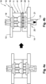
- the Fig. 4a and 4b show a sequence of a process for opening the mold 11. This process is in principle also comparable with the Fig. 1 to 3 described casting machines.
- the Fig. 4a shows the casting mold 11 between the upper clamping plate 13 and the lower clamping plate 14 of the casting machine 10 shown here only partially Fig. 1
- the casting mold 11 is completely closed and the cavity 18 is filled with a melt which, in the solidified state, forms a product 41.
- the casting mold 11 is now opened by the product 41 being formed from the lower mold part 17 using the lower ejector 20, the upper mold part 16 being separated from the lower mold part 17 and the casting mold 11 being opened.
- the product 41 initially remains in the upper mold part 16.
- An opening force is caused by the product 41 being lifted via the ejector cylinder 23, the ejector plate 21 and the rods 22.
- a locking cylinder (not shown here) is not actuated or is depressurized.
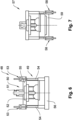
- FIG. 5a and 5b shows in contrast to the one with the Fig. 4a and 4b illustrated method steps, an opening of a casting mold 42, wherein here an upper ejector 43 and a lower ejector 44 are actuated simultaneously for opening and thus an opening force can be caused to separate an upper mold part 45 from a lower mold part 46.
- the lower ejector 44 is designed here with opening rods 47, which cause the opening force directly on the opposite upper mold part 46. This means that the opening rods 47 come into contact directly on the opposite upper mold part 46 when the lower ejector 44 is actuated to open the casting mold 42.
- the lower ejector 44 can also be designed without the opening rods 47.
- the Fig. 6 shows an embodiment of a casting machine 48 with a casting mold 49 with only one ejector or upper ejector 50.
- the upper ejector 50 is designed here so that in addition to an ejector cylinder 51, which acts directly on an ejector plate 52, two further ejector cylinders 53 are provided.
- the further ejector cylinders 53 act on columns 54 in such a way that the casting mold 49 can be opened by a parallel and/or sequential actuation of the ejector cylinder 51 and the further ejector cylinders 53.
- the further ejector cylinders 53 are arranged on an upper clamping plate 55 and the columns 54 on a lower clamping plate 56.
- the Fig. 7 shows a casting machine 57 in which, in contrast to the casting machine from Fig. 6 further ejector cylinders 58 are arranged on a lower clamping plate 59.
- the Fig. 8a to 8c show a further sequence of a process sequence or demoulding process with a casting machine 60 and the casting mould 11.
- An upper ejector 61 with two ejector cylinders is designed here.
- an opening force is initially exerted by the upper ejector 61 on the lower mold part 17, so that the upper mold part 16 lifts off from it and the product 41 remains in the lower mold part 17.
- the lower ejector 44 is actuated so that the product 41 is also separated from the lower mold part 17.
- the upper mold part 16 was previously completely removed so that the product 41 can be easily removed.
- the Fig. 9 shows a casting machine 63 in which, in contrast to the casting machine from Fig. 8 an upper ejector 64 is formed with opening rods 65. With the casting machine 63, the Fig. 8a to 8c The procedures described can also be carried out.
- FIG. 10a to 10c shows a further embodiment of a casting process in which, in contrast to the casting process according to the Fig. 4a and 4b a casting machine 66 is used which has an upper ejector 67 with two ejector cylinders 68. Furthermore, a central column 69 is provided for guiding an upper clamping plate 70.
- the Fig. 11a to 11c show a casting process with a casting machine 71 in which, in contrast to the Fig. 4a and 4b a lower ejector 72 of the casting machine 71 is designed with two ejector cylinders 73.
Landscapes
- Engineering & Computer Science (AREA)
- Mechanical Engineering (AREA)
- Moulds For Moulding Plastics Or The Like (AREA)
Priority Applications (2)
| Application Number | Priority Date | Filing Date | Title |
|---|---|---|---|
| EP23178422.4A EP4474077A1 (fr) | 2023-06-09 | 2023-06-09 | Machine de coulée et procédé de coulée d'un produit |
| CN202410731689.9A CN119098578A (zh) | 2023-06-09 | 2024-06-06 | 铸造机以及用于铸造产品的方法 |
Applications Claiming Priority (1)
| Application Number | Priority Date | Filing Date | Title |
|---|---|---|---|
| EP23178422.4A EP4474077A1 (fr) | 2023-06-09 | 2023-06-09 | Machine de coulée et procédé de coulée d'un produit |
Publications (1)
| Publication Number | Publication Date |
|---|---|
| EP4474077A1 true EP4474077A1 (fr) | 2024-12-11 |
Family
ID=86760206
Family Applications (1)
| Application Number | Title | Priority Date | Filing Date |
|---|---|---|---|
| EP23178422.4A Pending EP4474077A1 (fr) | 2023-06-09 | 2023-06-09 | Machine de coulée et procédé de coulée d'un produit |
Country Status (2)
| Country | Link |
|---|---|
| EP (1) | EP4474077A1 (fr) |
| CN (1) | CN119098578A (fr) |
Citations (1)
| Publication number | Priority date | Publication date | Assignee | Title |
|---|---|---|---|---|
| CN110421141A (zh) * | 2019-09-17 | 2019-11-08 | 周立 | 一种薄壁件压铸模具 |
-
2023
- 2023-06-09 EP EP23178422.4A patent/EP4474077A1/fr active Pending
-
2024
- 2024-06-06 CN CN202410731689.9A patent/CN119098578A/zh active Pending
Patent Citations (1)
| Publication number | Priority date | Publication date | Assignee | Title |
|---|---|---|---|---|
| CN110421141A (zh) * | 2019-09-17 | 2019-11-08 | 周立 | 一种薄壁件压铸模具 |
Also Published As
| Publication number | Publication date |
|---|---|
| CN119098578A (zh) | 2024-12-10 |
Similar Documents
| Publication | Publication Date | Title |
|---|---|---|
| DE69317205T2 (de) | Spritzgiessmaschine vom örtlichen Druckbeaufschlagungstyp | |
| DE3205262A1 (de) | Spritzgiessmaschine | |
| WO2017174670A1 (fr) | Dispositif de production de pièces en fonte, telle que de la fonte d'aluminium, dans le procédé à pression | |
| EP2100678B1 (fr) | Outil de coulée sous pression d'une machine de coulée sous pression | |
| DE69009118T2 (de) | Spritzgiessmaschine. | |
| DE3312539C1 (de) | Vorrichtung zum Herstellen von kastenlosen Sandgießformen | |
| EP0557995B1 (fr) | Installation pour le coulage sous pression d'objets en céramique, en particulier de cuvettes de W.C. | |
| CH206488A (de) | Giessform für Kunststoffe. | |
| EP3697554B1 (fr) | Moule de coulée sous pression pour la coulée de carters-cylindres ou de parties inférieures de carters de vilebrequin | |
| DE1902625A1 (de) | Spritzformverfahren und Spritzformmaschine zur Durchfuehrung des Verfahrens | |
| DE3879119T2 (de) | Verfahren zum giessen fluessigen metalles, insbesondere aluminiumlegierungen und magnesiumlegierungen und vorrichtung zu dessen durchfuehrung. | |
| DE102016118714B3 (de) | Gießwerkzeug,Verwendung eines solchen Gießwerkzeugs und Verfahren zum Gießen | |
| EP4474077A1 (fr) | Machine de coulée et procédé de coulée d'un produit | |
| EP2134528B1 (fr) | Moule avec cadre, à structure modulaire | |
| DE1558281B1 (de) | Druckgiessmaschine | |
| EP3511090B1 (fr) | Machine de coulée sous pression à chambre froide | |
| EP3108983B1 (fr) | Installation de coulee | |
| DE2050750B2 (de) | Einrichtung zum herstellen von kolben nach dem niederdruckgiessverfahren | |
| DE3234545C2 (de) | Vorrichtung zum Herstellen von SMC-Teilen | |
| DE102008004023A1 (de) | Verfahren und Vorrichtung zur Herstellung eines Gussteiles | |
| DE202017101592U1 (de) | Druckgussform | |
| DE2528645C3 (de) | Vorrichtung zur automatischen Herstellung kastenloser Gießformen | |
| DE2727257C3 (de) | Niederdruckgießmaschine | |
| DE2536142B2 (de) | Einrichtung zur Handhabung von Rotoren von Elektromotoren und zum Spritzgießen von Aluminiumkäfigwicklungen | |
| DE202017107328U1 (de) | Druckgussform |
Legal Events
| Date | Code | Title | Description |
|---|---|---|---|
| PUAI | Public reference made under article 153(3) epc to a published international application that has entered the european phase |
Free format text: ORIGINAL CODE: 0009012 |
|
| STAA | Information on the status of an ep patent application or granted ep patent |
Free format text: STATUS: THE APPLICATION HAS BEEN PUBLISHED |
|
| AK | Designated contracting states |
Kind code of ref document: A1 Designated state(s): AL AT BE BG CH CY CZ DE DK EE ES FI FR GB GR HR HU IE IS IT LI LT LU LV MC ME MK MT NL NO PL PT RO RS SE SI SK SM TR |
|
| STAA | Information on the status of an ep patent application or granted ep patent |
Free format text: STATUS: REQUEST FOR EXAMINATION WAS MADE |
|
| 17P | Request for examination filed |
Effective date: 20250521 |