EP2100678B1 - Outil de coulée sous pression d'une machine de coulée sous pression - Google Patents
Outil de coulée sous pression d'une machine de coulée sous pression Download PDFInfo
- Publication number
- EP2100678B1 EP2100678B1 EP08102489.5A EP08102489A EP2100678B1 EP 2100678 B1 EP2100678 B1 EP 2100678B1 EP 08102489 A EP08102489 A EP 08102489A EP 2100678 B1 EP2100678 B1 EP 2100678B1
- Authority
- EP
- European Patent Office
- Prior art keywords
- mold
- intermediate element
- relation
- die casting
- die
- Prior art date
- Legal status (The legal status is an assumption and is not a legal conclusion. Google has not performed a legal analysis and makes no representation as to the accuracy of the status listed.)
- Not-in-force
Links
- 238000004512 die casting Methods 0.000 title claims description 32
- 238000005266 casting Methods 0.000 claims abstract description 18
- 238000010008 shearing Methods 0.000 claims description 24
- 238000000465 moulding Methods 0.000 description 6
- 238000004519 manufacturing process Methods 0.000 description 4
- 238000000034 method Methods 0.000 description 4
- 238000010276 construction Methods 0.000 description 3
- 238000001746 injection moulding Methods 0.000 description 3
- 239000000155 melt Substances 0.000 description 2
- 238000000926 separation method Methods 0.000 description 2
- 239000007787 solid Substances 0.000 description 2
- 238000007711 solidification Methods 0.000 description 2
- 230000008023 solidification Effects 0.000 description 2
- 229910045601 alloy Inorganic materials 0.000 description 1
- 239000000956 alloy Substances 0.000 description 1
- 238000006073 displacement reaction Methods 0.000 description 1
- 238000002347 injection Methods 0.000 description 1
- 239000007924 injection Substances 0.000 description 1
- 239000007788 liquid Substances 0.000 description 1
- 229910001338 liquidmetal Inorganic materials 0.000 description 1
- 239000000463 material Substances 0.000 description 1
- 239000002184 metal Substances 0.000 description 1
- 229910001092 metal group alloy Inorganic materials 0.000 description 1
Images





Classifications
-
- B—PERFORMING OPERATIONS; TRANSPORTING
- B22—CASTING; POWDER METALLURGY
- B22D—CASTING OF METALS; CASTING OF OTHER SUBSTANCES BY THE SAME PROCESSES OR DEVICES
- B22D17/00—Pressure die casting or injection die casting, i.e. casting in which the metal is forced into a mould under high pressure
- B22D17/005—Pressure die casting or injection die casting, i.e. casting in which the metal is forced into a mould under high pressure using two or more fixed moulds
-
- B—PERFORMING OPERATIONS; TRANSPORTING
- B22—CASTING; POWDER METALLURGY
- B22D—CASTING OF METALS; CASTING OF OTHER SUBSTANCES BY THE SAME PROCESSES OR DEVICES
- B22D17/00—Pressure die casting or injection die casting, i.e. casting in which the metal is forced into a mould under high pressure
- B22D17/08—Cold chamber machines, i.e. with unheated press chamber into which molten metal is ladled
- B22D17/10—Cold chamber machines, i.e. with unheated press chamber into which molten metal is ladled with horizontal press motion
-
- B—PERFORMING OPERATIONS; TRANSPORTING
- B22—CASTING; POWDER METALLURGY
- B22D—CASTING OF METALS; CASTING OF OTHER SUBSTANCES BY THE SAME PROCESSES OR DEVICES
- B22D17/00—Pressure die casting or injection die casting, i.e. casting in which the metal is forced into a mould under high pressure
- B22D17/20—Accessories: Details
- B22D17/2076—Cutting-off equipment for sprues or ingates
-
- B—PERFORMING OPERATIONS; TRANSPORTING
- B22—CASTING; POWDER METALLURGY
- B22D—CASTING OF METALS; CASTING OF OTHER SUBSTANCES BY THE SAME PROCESSES OR DEVICES
- B22D17/00—Pressure die casting or injection die casting, i.e. casting in which the metal is forced into a mould under high pressure
- B22D17/20—Accessories: Details
- B22D17/22—Dies; Die plates; Die supports; Cooling equipment for dies; Accessories for loosening and ejecting castings from dies
- B22D17/2236—Equipment for loosening or ejecting castings from dies
-
- B—PERFORMING OPERATIONS; TRANSPORTING
- B22—CASTING; POWDER METALLURGY
- B22D—CASTING OF METALS; CASTING OF OTHER SUBSTANCES BY THE SAME PROCESSES OR DEVICES
- B22D17/00—Pressure die casting or injection die casting, i.e. casting in which the metal is forced into a mould under high pressure
- B22D17/20—Accessories: Details
- B22D17/26—Mechanisms or devices for locking or opening dies
- B22D17/266—Mechanisms or devices for locking or opening dies hydraulically
Definitions
- the invention relates to a die-casting tool of a die-casting machine, having a first mold, which has a first and a second mold part, which are movable linearly relative to one another for mold closing and mold opening and form at least one mold cavity between them, and with at least one casting run, wherein at least one further, second mold having a third and a fourth mold part, which are aligned for form closure and mold opening rectified to the mold parts of the first form linearly movable and form at least one further mold cavity between them, wherein a molded part of the first mold and a molded part of the second mold back are arranged to each other back and record between them an intermediate element having the casting run and wherein the casting run leads to both mold cavities.
- Diecasting tools of the type mentioned are known. They are used in a die casting machine. For filling (shot) of the mold cavity, a hot, liquid medium, for example a metal, a metal alloy or plastic, is placed over the run over the runner. Previously, the form consisting of a first and a second molded part must be closed. If the medium in the casting chamber and the mold cavity solidifies, the two mold parts are moved apart. by virtue of This procedure limits the number of workpieces that can be produced per unit of time. In order to increase the number of workpieces, several casting depressions for forming a plurality of mold cavities may be present in the two mold parts. However, the area available for this is limited due to the materials to be handled, the mold closing pressure to be applied and so on.
- the disclosure DE 10225165 A1 a universal mold with a stack mold for an injection molding system.
- Gb-A-1569382 It is a low-pressure casting process with two chambers filled from bottom to top.
- the gless chamber is located directly in the melt.
- the invention is therefore an object of the invention to provide a die-casting tool of a die-casting machine, which has a very high production capacity, that is, it can be created per unit of time a variety of cast workpieces.
- the intermediate element (4) is associated with a shearing device (21) for shearing off at least one sprue (24), preferably of both forms (2,3) sprue (24), and that the intermediate element (4 ) has at least two Auswerfervorurgien (19,20) for the two forms (2,3).
- a floor pressure die casting tool that is to say, the at least two shapes are arranged in the form of a tier, wherein superimposition or juxtaposition of the forms is meant here.
- multiple molds are used simultaneously, so that a corresponding increase in productivity sets.
- the invention is not limited to two forms, but it can also be used in terms of floor and more than two forms in superimposed and / or side-by-side construction.
- the arrangement is made such that at least one of the associated mold parts is linearly displaced to open the respective mold. This linear movement takes place transversely, in particular at right angles, to a mold parting plane.
- the individual levels of the multi-mold pressure tool will open for mold move linearly in the manner mentioned and linearly displaced to close the form in the corresponding opposite direction.
- the method and the displacement movement is always - as already mentioned - transversely, in particular at right angles to the individual mold parting planes of the molds, wherein the mold parting planes between the two mold parts of each mold are
- a medium for example with a liquid metal alloy can, is arranged between the at least two forms an intermediate element having the casting run.
- the at least two mold cavities of the at least two forms are filled.
- the molds are opened after solidification of the medium by linear separation.
- the casting run leads to both mold cavities. Consequently, the filling of both mold cavities can take place via a casting run.
- the invention is not limited to two mold cavities, but each of the at least two molds may have a plurality of mold cavities.
- the intermediate element a shearing device for shearing off at least one sprue, preferably a sprue of both forms.
- the shearing device In the region of the intermediate element, that is to say in the zone between the at least two forms, the shearing device is located. It shears off the runner formed in the run. It is particularly effective if a shearing device shears off the sprue of both forms, wherein there is preferably a common sprue for the shapes which is separated from the shearing device.
- the shearing device preferably has a linearly movable shearing knife, wherein the traversing direction of the shearing knife extends transversely, in particular at right angles to the linear traversing directions of the shaped parts.
- the intermediate element has at least two Auswerfervoriquesen for the two forms. Consequently, the ejection means are also accommodated in the intermediate element in order to empty the at least two molds.
- the Auswerfervortechnischen are therefore space-optimized between the two forms.
- the ejector devices have ejector cylinders, in particular block cylinders, which are arranged laterally of the molded parts, which adjoin the intermediate element.
- the space for positioning the Auswerfzylinder the Auswerfervorraumen is therefore used laterally adjacent to the intermediate element associated moldings.
- the ejector cylinders do not appear disturbing and use an otherwise unused space.
- the intermediate element preferably has two intermediate element parts, which are arranged back to back to each other. Each intermediate element part is assigned to one of the two forms.
- a development of the invention provides that the first mold part of the first mold is a solid mold part, to which - for mold closing and mold opening of the first mold - a unit consisting of the first mold part of the first mold, the intermediate element and the third mold part of the second mold is linearly movable and that to the unit - for mold closing and mold opening of the second mold - the fourth molding is linearly movable.
- the first mold part of the first mold retains its position, which is why it is a solid mold part. If the molds are to be opened, then a linear process of the unit, which consists of the second mold part of the first mold, the intermediate element and the third mold part of the second mold. At the same time, before or after, the fourth mold part is moved along a linear path to open the second mold. If more than two shapes are arranged on the floor, the above statements apply accordingly.
- the first molded part has a fixed, interchangeable mold insert and the second, third and fourth molded parts have moving, interchangeable mold inserts. All mold inserts are interchangeable to produce different workpieces, however, the first mold part has a fixed mold insert, because this does not change its position during operation of the die-casting tool.
- the word "fixed” therefore refers to the fixed positioning.
- the remaining moldings have moving mold inserts, because the moldings and thus their associated Move mold inserts when closing and opening the respective shape, so change their positions.
- a fixed platen and a linearly movable over guide columns, movable platen is provided, wherein between the two platen at least the two molds and at least one intermediate element are arranged.
- the two platens hold the stack of packages consisting of the mold parts and the intermediate element in the closed position of the molds and they move apart to open the molds. If more than two forms are present, more than one intermediate element is necessary because there is an intermediate element between each two forms.
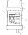
- the FIG. 1 shows a die-casting tool 1 in a die-casting machine not shown in detail, which has a first mold 2, a second mold 3 and an intermediate element 4 arranged between the two molds 2 and 3.
- the first mold 2 has a first molded part 5 and a second molded part 6.
- the second mold has a third mold part 7 and a fourth mold part 8.
- the intermediate element 4 is composed of two intermediate element parts 9 and 10.
- the respective plate-shaped moldings 5 to 8 and intermediate element parts 9 and 10 are - standing upright - surface to each other, wherein the first mold part 5 abuts the second mold part 6, the second mold part 6 rests on the intermediate element part 9, the intermediate element part 9 on the intermediate element part 10, the intermediate element part 10 on the third mold part 7 and the third mold part 7 on the fourth mold part 8.
- a parting plane is formed, wherein the parting planes parallel to each other and are vertical in the illustrated embodiment.
- the first mold part 5 is acted upon by a fixed platen 11, extending from the guide columns 12, 13, on which linearly displaceable a movable platen 14 superimposed, wherein between the two platen 11 and 14, the two molds 2 and 3 and the intermediate element 4 are arranged ,
- a drive device not shown
- the molds 2 and 3 and the intermediate element 4 clamp by means of the clamping plates 11 and 14 stacked together.
- the mold parts 5 and 6 and 7 and 8 are brought onto each other, so that a closed state of the molds 2 and 3 is present.
- At least one mold cavity is formed between the mold elements 5 and 6 or 7 and 8, so that - corresponding to the number of mold cavities formed - a corresponding number of workpieces can be produced by introducing a hot, solidifying medium in a filling channel 15.
- the filling channel 15 leads to a running between the two intermediate element parts 9 and 10 casting run 16 ( FIG. 2 ), so that the medium can flow through corresponding casting channels into the mold cavities.
- the molds 2 and 3 according to FIG. 2 open.
- a unit consisting of the molded part 6, the intermediate element 4 and the molded part 7 moves along the guide columns 12 and 13 in such a way that the molded parts 5 and 6 separate.
- the clamping plate 14 moves together with the molding 8 such that the mold 3 opens ( FIG. 2 ).
- FIG. 3 shows the completely disassembled state.
- the distances between the mold parts 5 and 6 on the one hand and 7 and 8 on the other hand are so large that a demolding of the produced workpieces 18 can be done easily.
- the two molds 2 and 3 are arranged in stack form with the interposition of the intermediate element 4. Since the medium is introduced by means of the intermediate element 4 in the two forms 2 and 3, they can be due to the intermediate position of the intermediate element 4 simultaneously and feed only one run 16. Furthermore, the intermediate element 4 has ejection devices 19 and 20, the ejection device 19 being assigned to the intermediate element part 9 and the ejection device 20 to the intermediate element part 10. In the area of the intermediate element 4 is - according to FIG. 1 - Further, a shearing device 21 (in the Figures 2 and 3 not shown), which serves for shearing a sprue. This is the solidified medium in the casting run 16. Hereinafter will be discussed in more detail.
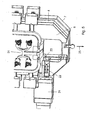
- FIGS. 4 and 5 show the shearing device 21, which has a slider 22 which is reciprocated linearly, with its direction of movement parallel to the parting planes - and thus perpendicular to the direction of movement of the molded parts - between the mold parts 5 to 8 and intermediate element parts 9 and 10 extends.
- the slide 22 is moved out of the shearing device 21, it meets a sprue 24.
- This consists of a fully or partially solidified medium and is freely accessible by moving apart of the intermediate element parts 9 and 10.
- the gate 24 is separated so that he - according to FIG. 5 - falls down (arrow 25). Subsequently, the shearing blade 23 (according to FIG. 5 ) are retracted again.
- FIGS. 6 to 8 clarify the representations of the FIGS. 1 to 3 .
- the workpieces 18 are removed from the mold.
- ejector plates 26 and 27, which belong to the ejector devices 19 and 20, are provided on the intermediate element parts 9 and 10.
- the Auswerfervoriquesen 19 and 20 have ejector 28 and 29, the laterally or after arranged above the mold parts 6 and 7 and formed as a block cylinder. They allow the application of an ejection force such that the workpieces 18 - as in FIG. 7 visible - ejected.
- the FIG. 8 shows a perspective view of the arrangement of FIG. 7 , but rotated about a vertical axis by 180 ° and in perspective view. It can be seen that the mold parts 5 to 8 each carry mold inserts 30 and 31, which are interchangeable to produce different workpieces 18 can.
- FIGS. 6 and 7 show that in the closed position, the stack of floors, which is formed by the first mold 2, the second mold 3 and the intermediate element 4, the distance d. In the fully open position according to FIG. 7 is the distance 2d, so it is about twice as large. Helleraus follows that the diecasting tool 1 according to the invention requires only a relatively small footprint for its operation and yet due to the multi-storey construction, a plurality of workpieces 18 per unit time can be made.
Landscapes
- Engineering & Computer Science (AREA)
- Mechanical Engineering (AREA)
- Molds, Cores, And Manufacturing Methods Thereof (AREA)
- Moulds For Moulding Plastics Or The Like (AREA)
Claims (7)
- Outil de coulée sous pression d'une machine de coulée sous pression, comprenant un premier moule qui présente une première et une deuxième partie de moule, lesquelles peuvent être déplacées linéairement l'une vers l'autre pour fermer et ouvrir le moule et forment entre elles au moins une cavité de moule, et comprenant au moins un canal de coulée, au moins un deuxième moule supplémentaire (3) étant prévu, lequel présente une troisième et une quatrième partie de moule (7, 8) qui peuvent être déplacées linéairement l'une vers l'autre pour fermer et ouvrir le moule dans le même sens que les parties de moule (5, 6) du premier moule (2) et forment entre elles au moins une cavité de moule supplémentaire, une partie de moule (5, 6) du premier moule (2) et une partie de moule (7, 8) du deuxième moule (3) étant disposées dos à dos l'une par rapport à l'autre et recevant entre elles un élément intermédiaire (4) qui présente le canal de coulée (16) et le canal de coulée (16) conduisant aux deux cavités de moule, caractérisé en ce qu'un dispositif de cisaillement (21) pour cisailler au moins une carotte (24) est associé à l'élément intermédiaire (4) et en ce que l'élément intermédiaire (4) présente au moins deux dispositifs d'éjection (19, 20) pour les deux moules (2, 3).
- Outil de coulée sous pression selon la revendication 1, caractérisé en ce que le dispositif de cisaillement (21) présente un couteau de cisaillement (23) déplaçable linéairement, la direction de déplacement du couteau de cisaillement (23) s'étendant transversalement, en particulier à angle droit par rapport aux directions de déplacement linéaires des parties de moule (5, 6, 7, 8).
- Outil de coulée sous pression selon la revendication 1, caractérisé en ce que les dispositifs d'éjection (19, 20) présentent des cylindres d'éjection (28), en particulier des cylindres-blocs qui sont disposés latéralement aux parties de moule (5, 6, 7, 8) qui sont adjacentes à l'élément intermédiaire (4).
- Outil de coulée sous pression selon l'une quelconque des revendications précédentes 1 à 3, caractérisé en ce que l'élément intermédiaire (4) présente deux parties d'élément intermédiaire (9, 10), qui sont disposées dos à dos l'une par rapport à l'autre.
- Outil de coulée sous pression selon l'une quelconque des revendications précédentes, caractérisé en ce que la première partie de moule (5) du premier moule est une partie de moule fixe (5), vers laquelle - pour ouvrir et fermer le premier moule (2) - peut être déplacée linéairement une unité constituée de la deuxième partie de moule (6) du premier moule (2), de l'élément intermédiaire (4) et de la troisième partie de moule (7) du deuxième moule (3) et en ce que la quatrième partie de moule (8) peut être déplacée linéairement vers l'unité - pour fermer et ouvrir le deuxième moule (3).
- Outil de coulée sous pression selon l'une quelconque des revendications précédentes, caractérisé en ce que la première partie de moule (5) présente un insert de moule fixe remplaçable (30) et en ce que la deuxième, troisième et quatrième partie de moule (6, 7, 8) possèdent des inserts de moule mobiles remplaçables (30, 31).
- Outil de coulée sous pression selon l'une quelconque des revendications précédentes, caractérisé par une plaque de serrage fixe (11) et une plaque de serrage mobile (14) déplaçable linéairement vers celle-ci par le biais de colonnes de guidage (12, 13), au moins les deux moules (2, 3) et au moins l'élément intermédiaire (4) étant disposés entre les deux plaques de serrage (11, 14).
Priority Applications (5)
| Application Number | Priority Date | Filing Date | Title |
|---|---|---|---|
| ES08102489.5T ES2453498T3 (es) | 2008-03-11 | 2008-03-11 | Herramienta de moldeo a presión de una máquina de moldeo a presión |
| EP08102489.5A EP2100678B1 (fr) | 2008-03-11 | 2008-03-11 | Outil de coulée sous pression d'une machine de coulée sous pression |
| JP2010550078A JP5458311B2 (ja) | 2008-03-11 | 2009-03-10 | ダイキャスト装置用のダイキャスト用具 |
| PCT/EP2009/001686 WO2009112230A1 (fr) | 2008-03-11 | 2009-03-10 | Outillage de coulée sous pression pour une machine de coulée sous pression |
| US12/921,727 US8434545B2 (en) | 2008-03-11 | 2009-03-10 | Die casting tool of a die casting machine |
Applications Claiming Priority (1)
| Application Number | Priority Date | Filing Date | Title |
|---|---|---|---|
| EP08102489.5A EP2100678B1 (fr) | 2008-03-11 | 2008-03-11 | Outil de coulée sous pression d'une machine de coulée sous pression |
Publications (2)
| Publication Number | Publication Date |
|---|---|
| EP2100678A1 EP2100678A1 (fr) | 2009-09-16 |
| EP2100678B1 true EP2100678B1 (fr) | 2013-12-25 |
Family
ID=39639492
Family Applications (1)
| Application Number | Title | Priority Date | Filing Date |
|---|---|---|---|
| EP08102489.5A Not-in-force EP2100678B1 (fr) | 2008-03-11 | 2008-03-11 | Outil de coulée sous pression d'une machine de coulée sous pression |
Country Status (5)
| Country | Link |
|---|---|
| US (1) | US8434545B2 (fr) |
| EP (1) | EP2100678B1 (fr) |
| JP (1) | JP5458311B2 (fr) |
| ES (1) | ES2453498T3 (fr) |
| WO (1) | WO2009112230A1 (fr) |
Cited By (2)
| Publication number | Priority date | Publication date | Assignee | Title |
|---|---|---|---|---|
| CN104028736A (zh) * | 2014-05-12 | 2014-09-10 | 新昌县东科精密机械有限公司 | 倾转式自动浇铸机 |
| DE102015203033A1 (de) * | 2015-02-19 | 2016-08-25 | Magna BDW technologies GmbH | Verfahren zur Herstellung eines dünnwandigen rotationssymmetrischen Bauteils aus Aluminium oder einer Aluminiumlegierung |
Families Citing this family (5)
| Publication number | Priority date | Publication date | Assignee | Title |
|---|---|---|---|---|
| CN102366826A (zh) * | 2011-09-28 | 2012-03-07 | 迈凯实金属技术(苏州)有限公司 | 一种集渣包容积可变的模具组件 |
| CN103600027B (zh) * | 2013-11-29 | 2015-08-05 | 成都成工工程机械井研铸造有限责任公司 | V法通用模板 |
| EP3191241A1 (fr) * | 2014-09-08 | 2017-07-19 | Siemens Aktiengesellschaft | Système de coulée sous pression hybride pour la formation d'un élément utilisable dans une turbine à gaz |
| DE202014106045U1 (de) * | 2014-12-15 | 2015-01-19 | Finke Formenbau Gmbh | Vorrichtung zum Nachbearbeiten eines Spritzgussbauteils und Anordnung mit mehreren Vorrichtungen |
| CA3003573A1 (fr) * | 2015-10-30 | 2017-05-04 | National Research Council Of Canada | Pieces metalliques incompatibles assemblees et procede d'assemblage |
Family Cites Families (15)
| Publication number | Priority date | Publication date | Assignee | Title |
|---|---|---|---|---|
| US1717254A (en) * | 1927-09-01 | 1929-06-11 | Polak Josef | Casting machine |
| US3791440A (en) * | 1970-12-07 | 1974-02-12 | R Cross | Die casting method |
| GB1569382A (en) * | 1977-06-22 | 1980-06-11 | Inst Litya Akad Nauk Ukrain Ss | Low pressure die-casting machine |
| JPS58189069U (ja) * | 1982-06-09 | 1983-12-15 | 株式会社菱沼製作所 | ダイカスト機におけるスプ−ル切断装置 |
| JPS6434559A (en) * | 1987-07-30 | 1989-02-06 | Seiko Epson Corp | Structure for taking out cavity |
| JPH0191950A (ja) * | 1987-09-30 | 1989-04-11 | Ahresty Corp | 複数製造の鋳造用マシン |
| US4981638A (en) * | 1988-01-29 | 1991-01-01 | Husky Injection Molding Systems Ltd. | Method and apparatus for clamping an injection unit to a molding machine |
| JPH02303673A (ja) * | 1989-05-16 | 1990-12-17 | Mazda Motor Corp | 金型鋳造方法およびその装置 |
| JPH0382512A (ja) * | 1989-08-25 | 1991-04-08 | Sodick Co Ltd | 両面成形の射出成形方法および射出成形機 |
| JPH0481256A (ja) * | 1990-07-23 | 1992-03-13 | Nissan Motor Co Ltd | ダイカスト鋳造装置 |
| US6171094B1 (en) * | 1993-11-01 | 2001-01-09 | John W. Von Holdt | Universal mold |
| JP2953990B2 (ja) * | 1995-05-19 | 1999-09-27 | ファナック株式会社 | 誘導電動機の籠形回転子の導体鋳造装置 |
| JPH09174220A (ja) * | 1995-12-25 | 1997-07-08 | Toyota Motor Corp | ダイカスト機 |
| DE19833598A1 (de) * | 1998-07-25 | 2000-02-24 | Mann & Hummel Filter | Werkzeug insbesondere zum Herstellen von Kernen |
| DE10225165A1 (de) * | 2002-06-06 | 2003-12-18 | Volkswagen Ag | Verfahren zum Herstellen von Spritzguß- insbesondere Druckgußbauteilen sowie Spritzgieß- oder Druckgußwerkzeuge |
-
2008
- 2008-03-11 EP EP08102489.5A patent/EP2100678B1/fr not_active Not-in-force
- 2008-03-11 ES ES08102489.5T patent/ES2453498T3/es active Active
-
2009
- 2009-03-10 WO PCT/EP2009/001686 patent/WO2009112230A1/fr not_active Ceased
- 2009-03-10 JP JP2010550078A patent/JP5458311B2/ja not_active Expired - Fee Related
- 2009-03-10 US US12/921,727 patent/US8434545B2/en not_active Expired - Fee Related
Cited By (2)
| Publication number | Priority date | Publication date | Assignee | Title |
|---|---|---|---|---|
| CN104028736A (zh) * | 2014-05-12 | 2014-09-10 | 新昌县东科精密机械有限公司 | 倾转式自动浇铸机 |
| DE102015203033A1 (de) * | 2015-02-19 | 2016-08-25 | Magna BDW technologies GmbH | Verfahren zur Herstellung eines dünnwandigen rotationssymmetrischen Bauteils aus Aluminium oder einer Aluminiumlegierung |
Also Published As
| Publication number | Publication date |
|---|---|
| JP5458311B2 (ja) | 2014-04-02 |
| ES2453498T3 (es) | 2014-04-08 |
| US8434545B2 (en) | 2013-05-07 |
| JP2011528281A (ja) | 2011-11-17 |
| WO2009112230A1 (fr) | 2009-09-17 |
| EP2100678A1 (fr) | 2009-09-16 |
| US20110030913A1 (en) | 2011-02-10 |
Similar Documents
| Publication | Publication Date | Title |
|---|---|---|
| EP2100678B1 (fr) | Outil de coulée sous pression d'une machine de coulée sous pression | |
| DE69416356T2 (de) | Vorrichtung und Verfahren zum Spritzgiessen mit örtlicher Druckbeaufschlagung | |
| EP2286974B1 (fr) | Dispositif de formage et procédé d'enlèvement d'un objet | |
| EP1938944B1 (fr) | Procédé pour la fabrication d'un corps en matière plastique multicouche | |
| DE19518963C2 (de) | Verfahren und Vorrichtung zum Spritzgießen hohlgeblasener Kunststoffkörper | |
| EP2929957A1 (fr) | Machine et procédé de coulée sous pression pour la fabrication de plusieurs pièces de fonderie | |
| DE69009118T2 (de) | Spritzgiessmaschine. | |
| EP0074473B1 (fr) | Procédé et dispositif pour la fabrication de pièces de forme ou des objets en matière plastique | |
| DE10110611C2 (de) | Vorrichtung zum Spritzgießen von Formkörpern aus Kunststoff | |
| DE102005011311B3 (de) | Schieberrückzug einer Spritzgießform und Verfahren zum Herstellen eines Spritzgießteils | |
| EP2623233B1 (fr) | Procédé de fabrication de pièces creuses coulées sous pression en aluminium | |
| CH206488A (de) | Giessform für Kunststoffe. | |
| EP2134528B1 (fr) | Moule avec cadre, à structure modulaire | |
| DE102008052950A1 (de) | Spritzgießmaschine | |
| EP1787784A1 (fr) | Moule pour la fabrication de pièces par moulage par injection, par moulage sous pression ou par un procédé de dépôt | |
| DE202017101592U1 (de) | Druckgussform | |
| DE10214466B4 (de) | Spritzgießmaschine | |
| EP2018236B1 (fr) | Procédé et moule pour la fabrication de pièces moulées | |
| EP1440782B1 (fr) | Appareil et procédé pour produire des objects plastiques en utilisant des moules à injecter avec des dispositifs de décélération de flux et leur utilisation | |
| DE69904654T2 (de) | Verfahren zum Spritzgiessen von Gegenständen aus synthetischen Polymeren/Copolymeren | |
| EP4474077A1 (fr) | Machine de coulée et procédé de coulée d'un produit | |
| DE3138242C2 (de) | Spritzgießverfahren zum Herstellen von Spritzgußteilen aus Thermoplasten und Spritzgießform zur Durchführung des Verfahrens | |
| DE102008056670B4 (de) | Verfahren zum Betreiben einer Spritzgießeinrichtung | |
| DE4416182C2 (de) | Spritzgießform zum Herstellen von rohrförmigen Spritzteilen mit Hinterschneidungen | |
| DE2727257C3 (de) | Niederdruckgießmaschine |
Legal Events
| Date | Code | Title | Description |
|---|---|---|---|
| PUAI | Public reference made under article 153(3) epc to a published international application that has entered the european phase |
Free format text: ORIGINAL CODE: 0009012 |
|
| AK | Designated contracting states |
Kind code of ref document: A1 Designated state(s): AT BE BG CH CY CZ DE DK EE ES FI FR GB GR HR HU IE IS IT LI LT LU LV MC MT NL NO PL PT RO SE SI SK TR |
|
| AX | Request for extension of the european patent |
Extension state: AL BA MK RS |
|
| 17P | Request for examination filed |
Effective date: 20100112 |
|
| 17Q | First examination report despatched |
Effective date: 20100407 |
|
| AKX | Designation fees paid |
Designated state(s): AT BE BG CH CY CZ DE DK EE ES FI FR GB GR HR HU IE IS IT LI LT LU LV MC MT NL NO PL PT RO SE SI SK TR |
|
| RAP1 | Party data changed (applicant data changed or rights of an application transferred) |
Owner name: GEORG FISCHER DIENSTLEISTUNGEN GMBH |
|
| GRAP | Despatch of communication of intention to grant a patent |
Free format text: ORIGINAL CODE: EPIDOSNIGR1 |
|
| INTG | Intention to grant announced |
Effective date: 20130719 |
|
| RAP1 | Party data changed (applicant data changed or rights of an application transferred) |
Owner name: GEORG FISCHER AUTOMOTIVE (SUZHOU) CO. LTD Owner name: GEORG FISCHER GMBH Owner name: GEORG FISCHER DRUCKGUSS GMBH & CO. KG Owner name: GEORG FISCHER GMBH & CO KG |
|
| GRAS | Grant fee paid |
Free format text: ORIGINAL CODE: EPIDOSNIGR3 |
|
| GRAA | (expected) grant |
Free format text: ORIGINAL CODE: 0009210 |
|
| AK | Designated contracting states |
Kind code of ref document: B1 Designated state(s): AT BE BG CH CY CZ DE DK EE ES FI FR GB GR HR HU IE IS IT LI LT LU LV MC MT NL NO PL PT RO SE SI SK TR |
|
| REG | Reference to a national code |
Ref country code: GB Ref legal event code: FG4D Free format text: NOT ENGLISH |
|
| REG | Reference to a national code |
Ref country code: CH Ref legal event code: EP Ref country code: CH Ref legal event code: NV Representative=s name: GEORG FISCHER AG, CH |
|
| REG | Reference to a national code |
Ref country code: AT Ref legal event code: REF Ref document number: 646312 Country of ref document: AT Kind code of ref document: T Effective date: 20140115 |
|
| REG | Reference to a national code |
Ref country code: IE Ref legal event code: FG4D Free format text: LANGUAGE OF EP DOCUMENT: GERMAN |
|
| REG | Reference to a national code |
Ref country code: DE Ref legal event code: R096 Ref document number: 502008011119 Country of ref document: DE Effective date: 20140213 |
|
| REG | Reference to a national code |
Ref country code: NL Ref legal event code: T3 |
|
| REG | Reference to a national code |
Ref country code: ES Ref legal event code: FG2A Ref document number: 2453498 Country of ref document: ES Kind code of ref document: T3 Effective date: 20140408 |
|
| PG25 | Lapsed in a contracting state [announced via postgrant information from national office to epo] |
Ref country code: NO Free format text: LAPSE BECAUSE OF FAILURE TO SUBMIT A TRANSLATION OF THE DESCRIPTION OR TO PAY THE FEE WITHIN THE PRESCRIBED TIME-LIMIT Effective date: 20140325 Ref country code: SE Free format text: LAPSE BECAUSE OF FAILURE TO SUBMIT A TRANSLATION OF THE DESCRIPTION OR TO PAY THE FEE WITHIN THE PRESCRIBED TIME-LIMIT Effective date: 20131225 Ref country code: LT Free format text: LAPSE BECAUSE OF FAILURE TO SUBMIT A TRANSLATION OF THE DESCRIPTION OR TO PAY THE FEE WITHIN THE PRESCRIBED TIME-LIMIT Effective date: 20131225 Ref country code: HR Free format text: LAPSE BECAUSE OF FAILURE TO SUBMIT A TRANSLATION OF THE DESCRIPTION OR TO PAY THE FEE WITHIN THE PRESCRIBED TIME-LIMIT Effective date: 20131225 Ref country code: FI Free format text: LAPSE BECAUSE OF FAILURE TO SUBMIT A TRANSLATION OF THE DESCRIPTION OR TO PAY THE FEE WITHIN THE PRESCRIBED TIME-LIMIT Effective date: 20131225 |
|
| PGFP | Annual fee paid to national office [announced via postgrant information from national office to epo] |
Ref country code: CH Payment date: 20140319 Year of fee payment: 7 Ref country code: NL Payment date: 20140319 Year of fee payment: 7 Ref country code: DE Payment date: 20140328 Year of fee payment: 7 |
|
| REG | Reference to a national code |
Ref country code: LT Ref legal event code: MG4D |
|
| PG25 | Lapsed in a contracting state [announced via postgrant information from national office to epo] |
Ref country code: LV Free format text: LAPSE BECAUSE OF FAILURE TO SUBMIT A TRANSLATION OF THE DESCRIPTION OR TO PAY THE FEE WITHIN THE PRESCRIBED TIME-LIMIT Effective date: 20131225 |
|
| PGFP | Annual fee paid to national office [announced via postgrant information from national office to epo] |
Ref country code: FR Payment date: 20140319 Year of fee payment: 7 Ref country code: IT Payment date: 20140324 Year of fee payment: 7 Ref country code: AT Payment date: 20140312 Year of fee payment: 7 |
|
| PG25 | Lapsed in a contracting state [announced via postgrant information from national office to epo] |
Ref country code: EE Free format text: LAPSE BECAUSE OF FAILURE TO SUBMIT A TRANSLATION OF THE DESCRIPTION OR TO PAY THE FEE WITHIN THE PRESCRIBED TIME-LIMIT Effective date: 20131225 Ref country code: IS Free format text: LAPSE BECAUSE OF FAILURE TO SUBMIT A TRANSLATION OF THE DESCRIPTION OR TO PAY THE FEE WITHIN THE PRESCRIBED TIME-LIMIT Effective date: 20140425 |
|
| PG25 | Lapsed in a contracting state [announced via postgrant information from national office to epo] |
Ref country code: SK Free format text: LAPSE BECAUSE OF FAILURE TO SUBMIT A TRANSLATION OF THE DESCRIPTION OR TO PAY THE FEE WITHIN THE PRESCRIBED TIME-LIMIT Effective date: 20131225 Ref country code: PL Free format text: LAPSE BECAUSE OF FAILURE TO SUBMIT A TRANSLATION OF THE DESCRIPTION OR TO PAY THE FEE WITHIN THE PRESCRIBED TIME-LIMIT Effective date: 20131225 Ref country code: CZ Free format text: LAPSE BECAUSE OF FAILURE TO SUBMIT A TRANSLATION OF THE DESCRIPTION OR TO PAY THE FEE WITHIN THE PRESCRIBED TIME-LIMIT Effective date: 20131225 Ref country code: PT Free format text: LAPSE BECAUSE OF FAILURE TO SUBMIT A TRANSLATION OF THE DESCRIPTION OR TO PAY THE FEE WITHIN THE PRESCRIBED TIME-LIMIT Effective date: 20140428 Ref country code: CY Free format text: LAPSE BECAUSE OF FAILURE TO SUBMIT A TRANSLATION OF THE DESCRIPTION OR TO PAY THE FEE WITHIN THE PRESCRIBED TIME-LIMIT Effective date: 20131225 Ref country code: RO Free format text: LAPSE BECAUSE OF FAILURE TO SUBMIT A TRANSLATION OF THE DESCRIPTION OR TO PAY THE FEE WITHIN THE PRESCRIBED TIME-LIMIT Effective date: 20131225 |
|
| REG | Reference to a national code |
Ref country code: DE Ref legal event code: R097 Ref document number: 502008011119 Country of ref document: DE |
|
| PG25 | Lapsed in a contracting state [announced via postgrant information from national office to epo] |
Ref country code: LU Free format text: LAPSE BECAUSE OF FAILURE TO SUBMIT A TRANSLATION OF THE DESCRIPTION OR TO PAY THE FEE WITHIN THE PRESCRIBED TIME-LIMIT Effective date: 20140311 Ref country code: DK Free format text: LAPSE BECAUSE OF FAILURE TO SUBMIT A TRANSLATION OF THE DESCRIPTION OR TO PAY THE FEE WITHIN THE PRESCRIBED TIME-LIMIT Effective date: 20131225 |
|
| PLBE | No opposition filed within time limit |
Free format text: ORIGINAL CODE: 0009261 |
|
| STAA | Information on the status of an ep patent application or granted ep patent |
Free format text: STATUS: NO OPPOSITION FILED WITHIN TIME LIMIT |
|
| GBPC | Gb: european patent ceased through non-payment of renewal fee |
Effective date: 20140325 |
|
| 26N | No opposition filed |
Effective date: 20140926 |
|
| REG | Reference to a national code |
Ref country code: IE Ref legal event code: MM4A |
|
| REG | Reference to a national code |
Ref country code: DE Ref legal event code: R097 Ref document number: 502008011119 Country of ref document: DE Effective date: 20140926 |
|
| PG25 | Lapsed in a contracting state [announced via postgrant information from national office to epo] |
Ref country code: IE Free format text: LAPSE BECAUSE OF NON-PAYMENT OF DUE FEES Effective date: 20140311 Ref country code: GB Free format text: LAPSE BECAUSE OF NON-PAYMENT OF DUE FEES Effective date: 20140325 |
|
| PG25 | Lapsed in a contracting state [announced via postgrant information from national office to epo] |
Ref country code: SI Free format text: LAPSE BECAUSE OF FAILURE TO SUBMIT A TRANSLATION OF THE DESCRIPTION OR TO PAY THE FEE WITHIN THE PRESCRIBED TIME-LIMIT Effective date: 20131225 |
|
| REG | Reference to a national code |
Ref country code: DE Ref legal event code: R119 Ref document number: 502008011119 Country of ref document: DE |
|
| REG | Reference to a national code |
Ref country code: CH Ref legal event code: PL |
|
| REG | Reference to a national code |
Ref country code: AT Ref legal event code: MM01 Ref document number: 646312 Country of ref document: AT Kind code of ref document: T Effective date: 20150311 |
|
| REG | Reference to a national code |
Ref country code: NL Ref legal event code: MM Effective date: 20150401 |
|
| PG25 | Lapsed in a contracting state [announced via postgrant information from national office to epo] |
Ref country code: IT Free format text: LAPSE BECAUSE OF NON-PAYMENT OF DUE FEES Effective date: 20150311 |
|
| REG | Reference to a national code |
Ref country code: FR Ref legal event code: ST Effective date: 20151130 |
|
| PG25 | Lapsed in a contracting state [announced via postgrant information from national office to epo] |
Ref country code: CH Free format text: LAPSE BECAUSE OF NON-PAYMENT OF DUE FEES Effective date: 20150331 Ref country code: DE Free format text: LAPSE BECAUSE OF NON-PAYMENT OF DUE FEES Effective date: 20151001 Ref country code: LI Free format text: LAPSE BECAUSE OF NON-PAYMENT OF DUE FEES Effective date: 20150331 |
|
| PG25 | Lapsed in a contracting state [announced via postgrant information from national office to epo] |
Ref country code: AT Free format text: LAPSE BECAUSE OF NON-PAYMENT OF DUE FEES Effective date: 20150311 Ref country code: MT Free format text: LAPSE BECAUSE OF FAILURE TO SUBMIT A TRANSLATION OF THE DESCRIPTION OR TO PAY THE FEE WITHIN THE PRESCRIBED TIME-LIMIT Effective date: 20131225 Ref country code: FR Free format text: LAPSE BECAUSE OF NON-PAYMENT OF DUE FEES Effective date: 20150331 |
|
| REG | Reference to a national code |
Ref country code: ES Ref legal event code: FD2A Effective date: 20160427 |
|
| PG25 | Lapsed in a contracting state [announced via postgrant information from national office to epo] |
Ref country code: BG Free format text: LAPSE BECAUSE OF FAILURE TO SUBMIT A TRANSLATION OF THE DESCRIPTION OR TO PAY THE FEE WITHIN THE PRESCRIBED TIME-LIMIT Effective date: 20131225 Ref country code: MC Free format text: LAPSE BECAUSE OF FAILURE TO SUBMIT A TRANSLATION OF THE DESCRIPTION OR TO PAY THE FEE WITHIN THE PRESCRIBED TIME-LIMIT Effective date: 20131225 |
|
| PG25 | Lapsed in a contracting state [announced via postgrant information from national office to epo] |
Ref country code: GR Free format text: LAPSE BECAUSE OF FAILURE TO SUBMIT A TRANSLATION OF THE DESCRIPTION OR TO PAY THE FEE WITHIN THE PRESCRIBED TIME-LIMIT Effective date: 20140326 |
|
| PG25 | Lapsed in a contracting state [announced via postgrant information from national office to epo] |
Ref country code: ES Free format text: LAPSE BECAUSE OF NON-PAYMENT OF DUE FEES Effective date: 20150312 Ref country code: HU Free format text: LAPSE BECAUSE OF FAILURE TO SUBMIT A TRANSLATION OF THE DESCRIPTION OR TO PAY THE FEE WITHIN THE PRESCRIBED TIME-LIMIT; INVALID AB INITIO Effective date: 20080311 Ref country code: TR Free format text: LAPSE BECAUSE OF FAILURE TO SUBMIT A TRANSLATION OF THE DESCRIPTION OR TO PAY THE FEE WITHIN THE PRESCRIBED TIME-LIMIT Effective date: 20131225 Ref country code: BE Free format text: LAPSE BECAUSE OF FAILURE TO SUBMIT A TRANSLATION OF THE DESCRIPTION OR TO PAY THE FEE WITHIN THE PRESCRIBED TIME-LIMIT Effective date: 20140331 |
|
| PG25 | Lapsed in a contracting state [announced via postgrant information from national office to epo] |
Ref country code: NL Free format text: LAPSE BECAUSE OF NON-PAYMENT OF DUE FEES Effective date: 20150401 |