EP4474110A2 - Auxiliaire de travail - Google Patents
Auxiliaire de travail Download PDFInfo
- Publication number
- EP4474110A2 EP4474110A2 EP24200916.5A EP24200916A EP4474110A2 EP 4474110 A2 EP4474110 A2 EP 4474110A2 EP 24200916 A EP24200916 A EP 24200916A EP 4474110 A2 EP4474110 A2 EP 4474110A2
- Authority
- EP
- European Patent Office
- Prior art keywords
- stand
- aid
- support
- working
- feet
- Prior art date
- Legal status (The legal status is an assumption and is not a legal conclusion. Google has not performed a legal analysis and makes no representation as to the accuracy of the status listed.)
- Pending
Links
Images



Classifications
-
- B—PERFORMING OPERATIONS; TRANSPORTING
- B25—HAND TOOLS; PORTABLE POWER-DRIVEN TOOLS; MANIPULATORS
- B25H—WORKSHOP EQUIPMENT, e.g. FOR MARKING-OUT WORK; STORAGE MEANS FOR WORKSHOPS
- B25H1/00—Work benches; Portable stands or supports for positioning portable tools or work to be operated on thereby
- B25H1/0021—Stands, supports or guiding devices for positioning portable tools or for securing them to the work
Definitions
- the present invention relates to a working aid according to the preamble of claim 1.
- Work aids with a support for a workpiece are used in a variety of ways in trade, industry and the home to enable certain activities to be carried out easily, comfortably and/or at all.
- the object of the present invention is to provide a work aid that can be used for numerous different work cases.
- the work aid should preferably be mobile and easy to transport. In particular, it should be simple in structure, inexpensive in construction and comfortable and easy to understand to use.
- the inventors realized that this task can be solved in a surprising way and particularly easily if the work aid has swivel feet, because it can then be easily adapted to certain floor conditions. In addition, it can be easily reduced in size and thus easily transported.
- the work aid according to the invention with a stand that has a longitudinal axis, wherein a stand element for placing the work aid on a floor and a support for a workpiece are arranged on the stand, is characterized in that the stand element has at least three feet that are arranged to be pivotable from a pivoted-out position to a pivoted-in position with respect to the longitudinal axis. With three feet, the stand can be particularly easily adapted to different, especially for uneven floors. If there are four or more feet, the load supported by the work aid is distributed particularly well.
- the feet are designed to be fixable in the swung-out position and/or in the swung-in position. This makes the work aid particularly safe to stand on a floor.
- the feet are in a form-fitting position against the stand element in the swiveled-out position. This means that the work aid stands particularly securely on a floor, even when the workpiece is subject to high loads.
- the feet are accommodated in corresponding guides, whereby the feet have an elongated hole through which an axis of the respective guides extends for pivoting the foot accommodated in the guide. This allows pivoting to be carried out very easily and safely.
- the guides in relation to the longitudinal axis have an opening above and below the axis for the passage of the corresponding foot in its pivoted-in position. This makes the work aid particularly compact when the feet are pivoted in, while still ensuring a high load-bearing capacity of the stand element.
- the guides in relation to the axis between the longitudinal axis and the axis below the corresponding foot arranged in its swiveled-out position have a support to prevent the foot from swiveling. This ensures that the work aid stands particularly securely on a floor even when the workpiece is subject to high loads.
- the guides in relation to the axis opposite the longitudinal axis above the corresponding foot arranged in its swiveled-out position have a support to prevent the foot from swiveling. This also ensures that the work aid stands particularly securely on a floor even when the workpiece is subject to high loads.
- the feet are inserted into pockets on the stand element in the swiveled-out position. This ensures that the work aid stands particularly securely on a floor, even when the workpiece is subject to high loads.
- a fixing means is arranged on the axle, which is preferably designed as a nut for clamping the foot in the guide. This makes the stand of the work aid on a floor even safer because it prevents it from swinging in accidentally.
- the guide has two legs that run parallel to the plane, with the foot preferably being designed as a sheet metal part. This makes the stand element particularly simple in construction and at the same time stable.
- the stand is provided with stops for the feet in their swiveled-out position, with the stops preferably being surrounded on all sides by the corresponding guide. This also further improves the stability of the work aid.
- the stand is designed to be telescopic with at least one stand part running into another.
- the work aid can then be easily adapted to many different activities.
- the stand extends beyond the guides to the floor. This makes the work aid particularly stable, even with high workpiece loads and for different heights.
- the stand could be arranged in the same plane as the feet when the feet are swung out, so that the work aid not only stands on the feet, but also on the stand itself.
- the stand part running in the other stand part has several equally spaced openings and in the other part of the stand there is an opening through which a bolt can be pushed, the bolt preferably being designed to be lockable and preferably having a stop and an opening for a locking pin opposite the stop.
- the distance between the openings is preferably in the range 10 mm to 50 mm, preferably in the range 20 mm to 30 mm and is in particular 25 mm.
- a stand part has a thread in which a threaded rod is arranged, with a nut preferably arranged on the threaded rod for locking against the stand part.
- the thread pitch is preferably in the range 1.0 mm to 5.0 mm, preferably in the range 1.5 mm to 3.0 mm and is in particular 2.5 mm. With a thread pitch of 2.5 mm, there is a particularly fine adjustment, since a stroke of approx. 0.6 mm is achieved with a quarter turn. In addition, a breakthrough distance of 25 mm is compensated for over 10 thread turns.
- the support has two first rotatable elements. This makes it particularly easy to guide workpieces over the support. Independent protection is required for this design. Within the scope of this independent protection, it is therefore not important whether the stand element has at least three feet that are arranged to be pivotable from a pivoted-out position to a pivoted-in position in relation to the longitudinal axis, but it is only obligatory that the support has two first rotatable elements.
- the distance between the first rotatable elements is designed to be selectively adjustable. This means that the support can be very easily adapted to workpieces of different sizes.
- the axes of the first two rotatable elements are on one line or on two different lines. If the axes of the rotatable elements are on one line, workpieces can be transported particularly easily over the support between the two rotatable elements.
- pipes or similar workpieces can be safely guided, especially for cutting to length, sawing, etc.
- applications include cutting, sawing and grinding, as well as the storage of larger and heavier materials during processing, such as milling.
- workpieces can be rotated around a workpiece's longitudinal axis between the two rotating elements, particularly on the support. This makes it possible, for example, to "roll" the workpiece between the two axes. This makes it possible, for example, to place a pipe on a welding table in order to weld round covers without setting them down using an electrode or using the TIG welding process without setting them down. Furthermore, with this design, the weld seams can then be machined on a grinding machine.
- first rotatable elements there are four first rotatable elements, with two first rotatable elements each lying on a common axis and the two axes being arranged parallel and spaced apart from one another. Then, either a workpiece transport over the support or a workpiece rotation can be carried out, depending on how the workpiece is placed on the first rotatable elements.
- a pivoting element on which a second rotatable element is arranged the second rotatable element being arranged so as to be pivotable with the aid of the pivoting element from a rest position below the support surface of the first rotatable elements to a working position above the support surface of the first rotatable elements, the rest position and/or the working position preferably being designed so as to be fixable.
- Workpieces can then be guided on the support in a very defined manner between the first rotatable elements and the second rotatable element.
- workpieces can also be placed and transported directly on the second rotatable element. If the second rotatable element is designed as a wide roller, materials that are flat and wide, such as flat iron, square tubes, boards, beams, etc., can also be unrolled. These workpieces can then be easily cut to length.
- first rotatable elements and/or the second rotatable element are designed as a wheel or roller. This makes it very easy to store and transport corresponding workpieces on the work aid.
- the pivoting element has two supports, in each of which one, preferably two, elongated hole guides are arranged. This makes it very easy to pivot and/or adjust the alignment of the second rotatable element relative to the first rotatable elements.
- the supports are arranged so that they can pivot on an axis of the support. This also makes it very easy to pivot and/or adjust the alignment of the second rotatable element relative to the first rotatable elements.
- the supports rest on two shelves in the rest position of the pivoting element and are accommodated between the shelves in the working position, with the shelves preferably enclosing the supports in a form-fitting manner. This makes the work aid particularly stable even when the second rotatable element is used.
- the supports in the working position extend upwards beyond the second rotatable element in relation to the longitudinal axis.
- the supports then simultaneously form a guide for the workpiece so that it can be placed and transported more easily and safely on the work aid. If, on the other hand, the supports in the working position do not extend beyond the second If the workpieces extend upwards from the first rotating element, then workpieces that have a greater width than the second rotating element can also be placed and transported on the second rotating element.
- a cover that can be optionally arranged and removed above the first rotatable elements, preferably designed as a cover plate.
- the work aid can also be used to store workpieces that are not to be transported on the work aid, but only to be stored or supported.
- plasterboard can also be stored and cut using several work aids 10.
- the cover has an opening for fastening a pressure stamp, which is preferably provided with a buffer element. This means that even sensitive workpieces can be placed on the work aid. In addition, workpieces can be placed or supported in a defined manner on a relatively small support point.
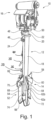
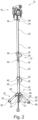
- the work aid 10 has a stand 12 with a longitudinal axis L, wherein a stand element 14 is arranged at the bottom of the stand 12 and a support 16 for a workpiece (not shown) is arranged at the top, i.e. opposite the stand element 14.
- the stand 12 has a first stand part 18, a second stand part 20 and a third stand part 22, which extend telescopically into one another. More precisely, the third stand part 22 runs in a form-fitting manner in the second stand part 22 and the second stand part 20 runs in a form-fitting manner in the first stand part 18.
- the first stand part 18 has a continuous opening 24 through which a bolt 26 can be pushed, which can be secured with a split pin 28.
- a stop 30 on the bolt 26 which rests against the first stand part 18 in the opening 24 when the bolt 26 is inserted.
- the second stand part 20 has continuous openings 32 arranged continuously in a certain grid, which have the same diameter as the opening 24, so that the bolt 26 can reach through both the opening 24 and one of the openings 32.
- the third stand part 22 Between the second stand part 20 and the third stand part 22 there is also a bolt 38 with an opening 39 for a split pin 40 and a stop 42 to determine the extension height.
- the third stand part 22 also has openings 44 arranged in the same notch.
- the first column part 18 has a square external cross-section of 40 mm x 40 mm with a wall thickness of 2 mm
- the second column part 20 has a square external cross-section of 35 mm x 35 mm with a wall thickness of 2 mm
- the third column part 22 has a square external cross-section of 30 mm x 30 mm with a wall thickness of 2 mm.
- the internal thread is on a metric nut M20 x 2.5, so that the threaded rod is also designed as M20 x 2.5, i.e. has a pitch of 2.5 mm for one complete revolution.
- the grid of the openings 32, 44 is 25 mm.
- the first stator part 18 has a square external cross-section of 60 mm x 60 mm with a wall thickness of 2 mm
- the second stator part 20 has a square external cross-section of 55 mm x 55 mm with a wall thickness of 2 mm
- the third stator part 22 has a square external cross-section of 50 mm x 50 mm with a wall thickness of 2 mm.
- the internal thread is on a metric nut M30 x 3.5, so that the threaded rod is also designed as M30 x 3.5, i.e. has a pitch of 3.5 mm for one complete revolution.
- the grid of the openings 32, 44 is 35 mm.
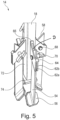
- the stand element 14 comprises four feet 52, each of which has a support element 54 with a support surface 56 arranged thereon. At the end of the feet 52 opposite the support surfaces 56, the support elements 54 are bevelled 58 so that the support elements 54 in the swung-out state (cf. Fig. 2 and 4 ) of the support elements 54 rest positively on the first stand part 18.
- the support elements 54 are each surrounded by a guide 60, which consists of two plane-parallel plates 62a, 62b, which are connected to one another via a web 64. This web 64 forms a stop for the support elements 54 when the support elements 54 are pivoted out.
- the guides 60 are welded to the first stand part 18 in such a way that a frame 66 is formed for the support element 54 which rests positively on the first stand part 18 in the swung-out state.
- These frames 66 thus form insertion pockets 66 for the support elements 54 so that they are additionally supported in the swung-out state.
- the plates 62a, 62b have no direct connection whatsoever, so that the support elements 54 can be freely pivoted between the plates 62a, 62b.
- the plates 62a, 62b have a continuous opening (not shown) through which a clamp 67 in the form of a screw 68 and a toggle nut 70 is guided.
- the support elements 54 have an elongated hole guide (not shown) which extends parallel to the longitudinal extension of the support elements 54 and through which the screw 68 is guided.
- the support elements 54 When fully swung out and inserted into the pockets 66, the support elements 54 rest against the first stand part 18 in a form-fitting manner. They also engage in the pockets 66 in a form-fitting manner and rest against the web 64 (cf. Fig. 2 and 4 ). They can be additionally secured by the clamp 67, whereby the two plates 62a, 62b clamp the support element 54 in a form-fitting manner.
- the feet 52 can support large loads and are still easy to swivel and require only a small amount of space when swivelled in (cf. Fig. 1 and 5 ) on.
- the first stand part 18 projects downwards over the surrounds 66 of the feet 52 and forms another foot 72, which is provided with a buffer 74.
- This foot 72 serves as a safety feature in case the feet 52 cannot withstand a certain load from a supported workpiece, which is why the foot 72 ends slightly above the level of the pivoted-out support surfaces 56 (cf. Fig. 2 ). Alternatively, the foot 72 could also end in the same plane as the pivoted-out shelves 56.
- the support 16 has a base 78 which is designed as a U-shaped channel and is firmly welded to the threaded rod 36.
- Flanges 82 are arranged on both sides of the base plate 80 of the base 78 via screw connections 84. These flanges 82 each have buffers 84 at their ends for safety reasons.
- an opening 86 is arranged centrally in the flanges 82.
- U-shaped holders 90a, 90b are arranged on the side surfaces 88a, 88b of the base 78, with openings (not shown) running through the side surfaces 92.
- a long nut 94 is arranged between the side surfaces 92.
- two elongated holes 96 arranged opposite the holders 90a, 90b are connected to the side surfaces 88a, 88b, with axes 98 being accommodated in opposite elongated holes 96 of the two side surfaces 88a, 88 so as to be displaceable in the longitudinal direction of the elongated holes 96.
- These axes 98 are fixed to one side 100 of legs 102.
- the other side 104 of the legs 102 has an opening (not shown) through which a threaded rod 106 extends, which is fixed on the other side 104 with two nuts 108, 110.
- Opposing threaded rods 106 are each held in the long nut 94, whereby the opposing threaded rods 106 have opposing threads (not shown).
- the distance between the opposing axes 98 can be continuously changed by rotating the long nut 94.
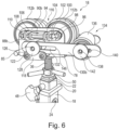
- Two wheels 112a, 112b are arranged on the axles 98 at a distance from each other, so that a gap 114 is formed between the wheels 112a, 112b of an axle 98 (cf. Fig. 7 ). Between the two axes 98, a gap 116 is formed (cf. Fig. 6 ), the width of which can be changed by means of the long nut 94, as described above.
- two shelves 120 are screwed 122 onto each of the two side surfaces 88a, 88b, which are connected to one another via a sheet metal 118 and are arranged horizontally adjacent to one another.
- a stop 124 with an internal thread (not shown) into which the threaded rod 126 of a knurled nut 128 can be screwed.
- a support 130a, 130b with an elongated hole 132 is placed on the threaded rod 126 and can be clamped against the stop 124 by means of the knurled nut 128.
- the two opposite supports 130a, 130b form a pivoting element 134 for a roller 136, the axis 138 of which is guided in elongated holes 140 of the supports 130a, 130b.
- the axis 138 has an external thread (not shown) on both sides, onto which knurled nuts 142 are screwed so that the position of the axis 138 can be fixed in the elongated holes 140.
- the roller 136 can be moved from a Fig. 6 shown rest position, in which the supports 130a, 130b each rest on the corresponding shelves 120 and the axle 138 is below the support surface of the wheels, into a working position in which the roller 136 is above the support surface of the wheels 112a, 112b and the supports 130a, 130b are held on both sides in a form-fitting manner between the shelves 120.
- the clamping with the knurled nut 128 is released and the supports 130a, 130b are first pulled with their lower ends 144 up to the threaded rods 126. Then the swivel element 134 is swivelled into the vertical position and then the supports 130a, 130b are lowered onto the threaded rods 126 up to the upper end 146 of the slot 132 and the knurled nuts 1128 are tightened and thereby fixed against the stop 124 by renewed clamping (cf. Fig. 7 ).
- the axis 138 can be aligned with respect to the supports 130a, 130b such that the supports 130a, 130b either protrude vertically over the roller 136 (cf. Fig. 7 , left side) or below the storage level of the roller 136 (cf. Fig. 7 , right side).
- cover 148 designed as a cover plate, which has a central horizontal section 150 and two sections 152a, 152b that run at an angle to it. Threaded rods 154 are welded to the inclined sections 152a, 152b, which extend downwards and can be inserted through the openings 86 of the flanges 82.
- the threaded rods 154 are spaced apart from one another such that they each fit into the gap 114. After the threaded rods 154 have been inserted into the openings 86, the threaded rods 154 can be fixed using corresponding nuts (not shown).
- the cover 148 has a central opening 158 with an internal thread (not shown) into which a pressure stamp 160 can be screwed, which for this purpose has a buffer element 162 which is fixed to a threaded rod 164, wherein the screwing of the threaded rod 164 into the opening 158 can be countered by means of a nut 166 (cf. Fig. 9 ).
- the length of the first stand part 18 is 620 mm up to its upper edge
- the length of the second stand part 20 is 520 mm up to its upper edge
- the length of the third stand part 22 is 730 mm up to the upper edge of the wheels 112a, 112b, 740 mm up to the upper edge of the cover 148, 790 mm up to the upper edge of the roller 136 and 820 mm up to the upper edge of the pressure stamp 160.
- the total height of the device in the fully extended state is 1960 mm.
- the threaded rod 36 is then unscrewed to the maximum. It can be adjusted by a total of 75 mm.
- the working aid 10 In its lowest setting with the feet 52 pivoted out, the working aid 10, with the second stand part 20 and the third stand part 22 each recessed, has a height of 778 mm to the upper edge of the wheels 112a, 112b, 784 mm to the upper edge of the cover 148 and 810 mm to the upper edge of the roller 136.
- a small jack (not shown) can be safely positioned on the surface of the cover plate 148, which is 100 mm x 120 mm.
- the jack is, for example, 150 mm high and has a stroke of 100 mm.
- the base area of the jack is 90 mm x 90 mm and is commercially available in this size.
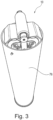
- the tool 10 is now used as follows: When the feet 52 are pivoted in, the entire device 10 with all additional parts can be accommodated and transported in a quiver 76 (cf. Fig. 3 ), whereby a lid serves to close the quiver 76 (in Fig. 3 not shown).
- the quiver 76 with lid has an outer diameter of 200 mm and a length of 900 mm.
- the height of the work aid 10 in the pivoted-in state of the stand element 14 up to the wheels 112a, 112b is 775 mm, while the work aid 10 reaches a maximum height of 1,880 mm.
- the working aid 10 is removed and the feet 52 are swung out after loosening the toggle nuts 70, inserted into the enclosures 66 and fixed again with the toggle nuts 70. Then, by loosening the screws 46, 48 the stand 12 is telescoped approximately to a desired length and first fixed by inserting the bolts 26, 38 into the openings 24, 32, 44 and then secured by the corresponding locking pins 28, 40 and tightening the locking screws 46, 48. The exact height is then determined by screwing the threaded rod 36 in or out of the head 34 of the third stand part 22 and this position is secured using the lock nut 50.
- the pressure stamp 160 can be removed from the cover 148 and the workpiece can be supported directly on the cover 148.
- the roller 136 is used for moving workpieces (not shown) that are flat.
- the swivel element 134 is released by loosening the knurled nuts 128, the lower end 144 of the supports 130a, 130b is pulled towards the threaded rods 126 and the swivel element 134 is swiveled into the vertical position.
- the swivel element 134 is then lowered, whereby the upper end 146 of the elongated holes 132 strikes the threaded rod 126 and the supports 130a, 130b are held in a form-fitting manner between the two shelves 120.
- the knurled screws are tightened again, thus securing the position of the swivel element 134.
- the roller 136 now rests on the wheels 112a, 112b and is supported by them, whereby a rotation of the roller 136 is transmitted to the wheels 112a, 112b.
- the supports 130a, 130b are not provided on the upper end 146 of their elongated hole 132 on the shelves 120, but are displaced upwards so far that they protrude above the roller 136.
- the position of the roller 136 in the supports 130a, 130b is determined by moving the axis 138 in the elongated holes 140 and secured by means of the knurled nuts 142.
- support is provided either in the slot 116, the width of which can be specifically adjusted by actuating the long nut 94, or support is provided in the slots 114.
- the first type of support in the slot 116 is suitable, for example, for machining weld seams of a pipe, while the second type of support in the slots 114 is suitable, for example, for cutting pipes or the like to length.
- workpieces can also be clamped between the wheels 112a, 112b and the roller 136.
- two or more work aids 10 can be used to support large workpieces (not shown). This could, for example, be used to lay down plasterboard for cutting to size.
- the present invention provides a work aid 10 that can be used for numerous different work cases.
- the work aid 10 is mobile and easy to transport. In addition, it is simple in structure, inexpensive in construction and comfortable and easy to understand to use.
Landscapes
- Engineering & Computer Science (AREA)
- Mechanical Engineering (AREA)
- Handcart (AREA)
- Agricultural Machines (AREA)
Applications Claiming Priority (3)
| Application Number | Priority Date | Filing Date | Title |
|---|---|---|---|
| DE102021134401.8A DE102021134401A1 (de) | 2021-12-22 | 2021-12-22 | Arbeitshilfsmittel |
| DE102021134402.6A DE102021134402A1 (de) | 2021-12-22 | 2021-12-22 | Arbeitshilfsmittel |
| EP22214691.2A EP4201599B1 (fr) | 2021-12-22 | 2022-12-19 | Auxiliaire de travail |
Related Parent Applications (2)
| Application Number | Title | Priority Date | Filing Date |
|---|---|---|---|
| EP22214691.2A Division-Into EP4201599B1 (fr) | 2021-12-22 | 2022-12-19 | Auxiliaire de travail |
| EP22214691.2A Division EP4201599B1 (fr) | 2021-12-22 | 2022-12-19 | Auxiliaire de travail |
Publications (2)
| Publication Number | Publication Date |
|---|---|
| EP4474110A2 true EP4474110A2 (fr) | 2024-12-11 |
| EP4474110A3 EP4474110A3 (fr) | 2025-01-01 |
Family
ID=84541366
Family Applications (2)
| Application Number | Title | Priority Date | Filing Date |
|---|---|---|---|
| EP24200916.5A Pending EP4474110A3 (fr) | 2021-12-22 | 2022-12-19 | Auxiliaire de travail |
| EP22214691.2A Active EP4201599B1 (fr) | 2021-12-22 | 2022-12-19 | Auxiliaire de travail |
Family Applications After (1)
| Application Number | Title | Priority Date | Filing Date |
|---|---|---|---|
| EP22214691.2A Active EP4201599B1 (fr) | 2021-12-22 | 2022-12-19 | Auxiliaire de travail |
Country Status (1)
| Country | Link |
|---|---|
| EP (2) | EP4474110A3 (fr) |
Family Cites Families (8)
| Publication number | Priority date | Publication date | Assignee | Title |
|---|---|---|---|---|
| US5064156A (en) * | 1990-04-12 | 1991-11-12 | Hirsh Company | Adjustable height work support |
| US5102079A (en) * | 1990-11-23 | 1992-04-07 | Lee Jin Ten | Connecting assembly for a tripod |
| US5060894A (en) * | 1991-04-22 | 1991-10-29 | Alltrade, Inc. | Stand with collapsible legs |
| AUPO727597A0 (en) * | 1997-06-12 | 1997-07-03 | Lewin, George | A multi-purpose folding support stand for woodworking and other uses |
| US6007032A (en) * | 1998-09-24 | 1999-12-28 | Kuo; Hua Tsung | Foldable stand assembly for microphones |
| US7641035B2 (en) * | 2003-10-09 | 2010-01-05 | Lee Valley Tools, Ltd. | Roller stand |
| US20050218275A1 (en) * | 2004-04-06 | 2005-10-06 | Allan Keating | Stand |
| US11065755B2 (en) * | 2019-10-08 | 2021-07-20 | Louis Chuang | Foot-operated bicycle work stand |
-
2022
- 2022-12-19 EP EP24200916.5A patent/EP4474110A3/fr active Pending
- 2022-12-19 EP EP22214691.2A patent/EP4201599B1/fr active Active
Also Published As
| Publication number | Publication date |
|---|---|
| EP4201599B1 (fr) | 2024-11-27 |
| EP4201599C0 (fr) | 2024-11-27 |
| EP4201599A1 (fr) | 2023-06-28 |
| EP4474110A3 (fr) | 2025-01-01 |
Similar Documents
| Publication | Publication Date | Title |
|---|---|---|
| EP0912299B1 (fr) | Table d'ouvrage pour travaux d'assemblage de pieces | |
| EP0541904A1 (fr) | Table, en particulier pour la préparation et le soudage | |
| DE4209752C2 (de) | Vorrichtung zum Befestigen von Messern in Lochungs- und Schneidzylindern von Maschinen des graphischen Gewerbes | |
| EP0637276B1 (fr) | Dispositif de pression pour machines a fraiser le bois | |
| DE2729304A1 (de) | Gehrungslade | |
| EP0065036B1 (fr) | Table à dessus réglable | |
| EP4201599B1 (fr) | Auxiliaire de travail | |
| EP3030378B1 (fr) | Outil de serrage | |
| DE19634156C1 (de) | Vorrichtung zum Handhaben einer Werkzeugmaschine | |
| DE102021134401A1 (de) | Arbeitshilfsmittel | |
| DE102021134402A1 (de) | Arbeitshilfsmittel | |
| DE3233586A1 (de) | Werkbank mit einer schwenkbaren arbeitsplatte | |
| CH635273A5 (de) | Vorrichtung zum loesbaren befestigen von werkstuecken an einem arbeitstisch. | |
| DE2428443A1 (de) | Einspannvorrichtung | |
| DE3234930C2 (de) | Vorrichtung zum Befestigen eines Auslegers an der zylindrischen Säule einer Säulenbohrmaschine | |
| DE4009528A1 (de) | Verbaueinrichtung fuer den grabenverbau | |
| DE3216935A1 (de) | Trennvorrichtung zum trennen von stangenmaterial | |
| DE102019128638A1 (de) | Vorrichtung zum verbinden eines ersten feststehenden mastteils mit einem gegenüber diesem klappbaren zweiten mastteil | |
| DE102012023901A1 (de) | Trennvorrichtung für Werkstücke, wie Stangen, Rohre und dergleichen, sowie Auflage, insbesondere zur Verwendung mit einer solchen Trennvorrichtung | |
| DE1477040A1 (de) | Werkzeughalter fuer Walzwerkzeuge | |
| DE29603128U1 (de) | Spannvorrichtung | |
| DE3233587C2 (fr) | ||
| DE102008045975A1 (de) | Spannvorrichtung | |
| DE2835948A1 (de) | Spann- und haltevorrichtung fuer verbauplatten | |
| DE1948464C3 (de) | Um drei Achsen schwenkbarer Aufspanntisch für Universal-Fräs- und/oder Bohrmaschinen |
Legal Events
| Date | Code | Title | Description |
|---|---|---|---|
| PUAI | Public reference made under article 153(3) epc to a published international application that has entered the european phase |
Free format text: ORIGINAL CODE: 0009012 |
|
| STAA | Information on the status of an ep patent application or granted ep patent |
Free format text: STATUS: THE APPLICATION HAS BEEN PUBLISHED |
|
| PUAL | Search report despatched |
Free format text: ORIGINAL CODE: 0009013 |
|
| AC | Divisional application: reference to earlier application |
Ref document number: 4201599 Country of ref document: EP Kind code of ref document: P |
|
| AK | Designated contracting states |
Kind code of ref document: A2 Designated state(s): AL AT BE BG CH CY CZ DE DK EE ES FI FR GB GR HR HU IE IS IT LI LT LU LV MC ME MK MT NL NO PL PT RO RS SE SI SK SM TR |
|
| AK | Designated contracting states |
Kind code of ref document: A3 Designated state(s): AL AT BE BG CH CY CZ DE DK EE ES FI FR GB GR HR HU IE IS IT LI LT LU LV MC ME MK MT NL NO PL PT RO RS SE SI SK SM TR |
|
| RIC1 | Information provided on ipc code assigned before grant |
Ipc: B25H 1/00 20060101AFI20241127BHEP |
|
| STAA | Information on the status of an ep patent application or granted ep patent |
Free format text: STATUS: REQUEST FOR EXAMINATION WAS MADE |
|
| 17P | Request for examination filed |
Effective date: 20250527 |