EP4474136A2 - Unité d'usinage au laser, module pour une unité d'usinage au laser et procédé de fabrication d'une pièce - Google Patents
Unité d'usinage au laser, module pour une unité d'usinage au laser et procédé de fabrication d'une pièce Download PDFInfo
- Publication number
- EP4474136A2 EP4474136A2 EP24178363.8A EP24178363A EP4474136A2 EP 4474136 A2 EP4474136 A2 EP 4474136A2 EP 24178363 A EP24178363 A EP 24178363A EP 4474136 A2 EP4474136 A2 EP 4474136A2
- Authority
- EP
- European Patent Office
- Prior art keywords
- platform
- powder material
- laser processing
- processing unit
- layer
- Prior art date
- Legal status (The legal status is an assumption and is not a legal conclusion. Google has not performed a legal analysis and makes no representation as to the accuracy of the status listed.)
- Withdrawn
Links
Images


Classifications
-
- B—PERFORMING OPERATIONS; TRANSPORTING
- B29—WORKING OF PLASTICS; WORKING OF SUBSTANCES IN A PLASTIC STATE IN GENERAL
- B29C—SHAPING OR JOINING OF PLASTICS; SHAPING OF MATERIAL IN A PLASTIC STATE, NOT OTHERWISE PROVIDED FOR; AFTER-TREATMENT OF THE SHAPED PRODUCTS, e.g. REPAIRING
- B29C64/00—Additive manufacturing, i.e. manufacturing of three-dimensional [3D] objects by additive deposition, additive agglomeration or additive layering, e.g. by 3D printing, stereolithography or selective laser sintering
- B29C64/10—Processes of additive manufacturing
- B29C64/141—Processes of additive manufacturing using only solid materials
- B29C64/153—Processes of additive manufacturing using only solid materials using layers of powder being selectively joined, e.g. by selective laser sintering or melting
-
- B—PERFORMING OPERATIONS; TRANSPORTING
- B22—CASTING; POWDER METALLURGY
- B22F—WORKING METALLIC POWDER; MANUFACTURE OF ARTICLES FROM METALLIC POWDER; MAKING METALLIC POWDER; APPARATUS OR DEVICES SPECIALLY ADAPTED FOR METALLIC POWDER
- B22F10/00—Additive manufacturing of workpieces or articles from metallic powder
- B22F10/20—Direct sintering or melting
- B22F10/28—Powder bed fusion, e.g. selective laser melting [SLM] or electron beam melting [EBM]
-
- B—PERFORMING OPERATIONS; TRANSPORTING
- B22—CASTING; POWDER METALLURGY
- B22F—WORKING METALLIC POWDER; MANUFACTURE OF ARTICLES FROM METALLIC POWDER; MAKING METALLIC POWDER; APPARATUS OR DEVICES SPECIALLY ADAPTED FOR METALLIC POWDER
- B22F12/00—Apparatus or devices specially adapted for additive manufacturing; Auxiliary means for additive manufacturing; Combinations of additive manufacturing apparatus or devices with other processing apparatus or devices
- B22F12/40—Radiation means
- B22F12/46—Radiation means with translatory movement
- B22F12/47—Radiation means with translatory movement parallel to the deposition plane
-
- B—PERFORMING OPERATIONS; TRANSPORTING
- B22—CASTING; POWDER METALLURGY
- B22F—WORKING METALLIC POWDER; MANUFACTURE OF ARTICLES FROM METALLIC POWDER; MAKING METALLIC POWDER; APPARATUS OR DEVICES SPECIALLY ADAPTED FOR METALLIC POWDER
- B22F12/00—Apparatus or devices specially adapted for additive manufacturing; Auxiliary means for additive manufacturing; Combinations of additive manufacturing apparatus or devices with other processing apparatus or devices
- B22F12/40—Radiation means
- B22F12/46—Radiation means with translatory movement
- B22F12/48—Radiation means with translatory movement in height, e.g. perpendicular to the deposition plane
-
- B—PERFORMING OPERATIONS; TRANSPORTING
- B22—CASTING; POWDER METALLURGY
- B22F—WORKING METALLIC POWDER; MANUFACTURE OF ARTICLES FROM METALLIC POWDER; MAKING METALLIC POWDER; APPARATUS OR DEVICES SPECIALLY ADAPTED FOR METALLIC POWDER
- B22F12/00—Apparatus or devices specially adapted for additive manufacturing; Auxiliary means for additive manufacturing; Combinations of additive manufacturing apparatus or devices with other processing apparatus or devices
- B22F12/50—Means for feeding of material, e.g. heads
- B22F12/52—Hoppers
-
- B—PERFORMING OPERATIONS; TRANSPORTING
- B29—WORKING OF PLASTICS; WORKING OF SUBSTANCES IN A PLASTIC STATE IN GENERAL
- B29C—SHAPING OR JOINING OF PLASTICS; SHAPING OF MATERIAL IN A PLASTIC STATE, NOT OTHERWISE PROVIDED FOR; AFTER-TREATMENT OF THE SHAPED PRODUCTS, e.g. REPAIRING
- B29C64/00—Additive manufacturing, i.e. manufacturing of three-dimensional [3D] objects by additive deposition, additive agglomeration or additive layering, e.g. by 3D printing, stereolithography or selective laser sintering
- B29C64/20—Apparatus for additive manufacturing; Details thereof or accessories therefor
- B29C64/205—Means for applying layers
- B29C64/214—Doctor blades
-
- B—PERFORMING OPERATIONS; TRANSPORTING
- B29—WORKING OF PLASTICS; WORKING OF SUBSTANCES IN A PLASTIC STATE IN GENERAL
- B29C—SHAPING OR JOINING OF PLASTICS; SHAPING OF MATERIAL IN A PLASTIC STATE, NOT OTHERWISE PROVIDED FOR; AFTER-TREATMENT OF THE SHAPED PRODUCTS, e.g. REPAIRING
- B29C64/00—Additive manufacturing, i.e. manufacturing of three-dimensional [3D] objects by additive deposition, additive agglomeration or additive layering, e.g. by 3D printing, stereolithography or selective laser sintering
- B29C64/20—Apparatus for additive manufacturing; Details thereof or accessories therefor
- B29C64/205—Means for applying layers
- B29C64/218—Rollers
-
- B—PERFORMING OPERATIONS; TRANSPORTING
- B29—WORKING OF PLASTICS; WORKING OF SUBSTANCES IN A PLASTIC STATE IN GENERAL
- B29C—SHAPING OR JOINING OF PLASTICS; SHAPING OF MATERIAL IN A PLASTIC STATE, NOT OTHERWISE PROVIDED FOR; AFTER-TREATMENT OF THE SHAPED PRODUCTS, e.g. REPAIRING
- B29C64/00—Additive manufacturing, i.e. manufacturing of three-dimensional [3D] objects by additive deposition, additive agglomeration or additive layering, e.g. by 3D printing, stereolithography or selective laser sintering
- B29C64/20—Apparatus for additive manufacturing; Details thereof or accessories therefor
- B29C64/264—Arrangements for irradiation
- B29C64/268—Arrangements for irradiation using laser beams; using electron beams [EB]
-
- B—PERFORMING OPERATIONS; TRANSPORTING
- B29—WORKING OF PLASTICS; WORKING OF SUBSTANCES IN A PLASTIC STATE IN GENERAL
- B29C—SHAPING OR JOINING OF PLASTICS; SHAPING OF MATERIAL IN A PLASTIC STATE, NOT OTHERWISE PROVIDED FOR; AFTER-TREATMENT OF THE SHAPED PRODUCTS, e.g. REPAIRING
- B29C64/00—Additive manufacturing, i.e. manufacturing of three-dimensional [3D] objects by additive deposition, additive agglomeration or additive layering, e.g. by 3D printing, stereolithography or selective laser sintering
- B29C64/30—Auxiliary operations or equipment
- B29C64/307—Handling of material to be used in additive manufacturing
- B29C64/321—Feeding
- B29C64/329—Feeding using hoppers
-
- B—PERFORMING OPERATIONS; TRANSPORTING
- B33—ADDITIVE MANUFACTURING TECHNOLOGY
- B33Y—ADDITIVE MANUFACTURING, i.e. MANUFACTURING OF THREE-DIMENSIONAL [3D] OBJECTS BY ADDITIVE DEPOSITION, ADDITIVE AGGLOMERATION OR ADDITIVE LAYERING, e.g. BY 3D PRINTING, STEREOLITHOGRAPHY OR SELECTIVE LASER SINTERING
- B33Y10/00—Processes of additive manufacturing
-
- B—PERFORMING OPERATIONS; TRANSPORTING
- B33—ADDITIVE MANUFACTURING TECHNOLOGY
- B33Y—ADDITIVE MANUFACTURING, i.e. MANUFACTURING OF THREE-DIMENSIONAL [3D] OBJECTS BY ADDITIVE DEPOSITION, ADDITIVE AGGLOMERATION OR ADDITIVE LAYERING, e.g. BY 3D PRINTING, STEREOLITHOGRAPHY OR SELECTIVE LASER SINTERING
- B33Y30/00—Apparatus for additive manufacturing; Details thereof or accessories therefor
-
- B—PERFORMING OPERATIONS; TRANSPORTING
- B22—CASTING; POWDER METALLURGY
- B22F—WORKING METALLIC POWDER; MANUFACTURE OF ARTICLES FROM METALLIC POWDER; MAKING METALLIC POWDER; APPARATUS OR DEVICES SPECIALLY ADAPTED FOR METALLIC POWDER
- B22F12/00—Apparatus or devices specially adapted for additive manufacturing; Auxiliary means for additive manufacturing; Combinations of additive manufacturing apparatus or devices with other processing apparatus or devices
- B22F12/10—Auxiliary heating means
- B22F12/13—Auxiliary heating means to preheat the material
-
- B—PERFORMING OPERATIONS; TRANSPORTING
- B22—CASTING; POWDER METALLURGY
- B22F—WORKING METALLIC POWDER; MANUFACTURE OF ARTICLES FROM METALLIC POWDER; MAKING METALLIC POWDER; APPARATUS OR DEVICES SPECIALLY ADAPTED FOR METALLIC POWDER
- B22F12/00—Apparatus or devices specially adapted for additive manufacturing; Auxiliary means for additive manufacturing; Combinations of additive manufacturing apparatus or devices with other processing apparatus or devices
- B22F12/10—Auxiliary heating means
- B22F12/17—Auxiliary heating means to heat the build chamber or platform
-
- B—PERFORMING OPERATIONS; TRANSPORTING
- B22—CASTING; POWDER METALLURGY
- B22F—WORKING METALLIC POWDER; MANUFACTURE OF ARTICLES FROM METALLIC POWDER; MAKING METALLIC POWDER; APPARATUS OR DEVICES SPECIALLY ADAPTED FOR METALLIC POWDER
- B22F12/00—Apparatus or devices specially adapted for additive manufacturing; Auxiliary means for additive manufacturing; Combinations of additive manufacturing apparatus or devices with other processing apparatus or devices
- B22F12/50—Means for feeding of material, e.g. heads
- B22F12/55—Two or more means for feeding material
-
- B—PERFORMING OPERATIONS; TRANSPORTING
- B22—CASTING; POWDER METALLURGY
- B22F—WORKING METALLIC POWDER; MANUFACTURE OF ARTICLES FROM METALLIC POWDER; MAKING METALLIC POWDER; APPARATUS OR DEVICES SPECIALLY ADAPTED FOR METALLIC POWDER
- B22F12/00—Apparatus or devices specially adapted for additive manufacturing; Auxiliary means for additive manufacturing; Combinations of additive manufacturing apparatus or devices with other processing apparatus or devices
- B22F12/60—Planarisation devices; Compression devices
- B22F12/63—Rollers
-
- B—PERFORMING OPERATIONS; TRANSPORTING
- B22—CASTING; POWDER METALLURGY
- B22F—WORKING METALLIC POWDER; MANUFACTURE OF ARTICLES FROM METALLIC POWDER; MAKING METALLIC POWDER; APPARATUS OR DEVICES SPECIALLY ADAPTED FOR METALLIC POWDER
- B22F12/00—Apparatus or devices specially adapted for additive manufacturing; Auxiliary means for additive manufacturing; Combinations of additive manufacturing apparatus or devices with other processing apparatus or devices
- B22F12/60—Planarisation devices; Compression devices
- B22F12/67—Blades
-
- B—PERFORMING OPERATIONS; TRANSPORTING
- B22—CASTING; POWDER METALLURGY
- B22F—WORKING METALLIC POWDER; MANUFACTURE OF ARTICLES FROM METALLIC POWDER; MAKING METALLIC POWDER; APPARATUS OR DEVICES SPECIALLY ADAPTED FOR METALLIC POWDER
- B22F12/00—Apparatus or devices specially adapted for additive manufacturing; Auxiliary means for additive manufacturing; Combinations of additive manufacturing apparatus or devices with other processing apparatus or devices
- B22F12/90—Means for process control, e.g. cameras or sensors
Definitions
- the invention relates to a laser processing unit which comprises a platform, a radiation source in the form of a laser with a scanning device, a material feed unit for applying a powder material and a carrier which mechanically couples the material guide unit to the scanning device, wherein the material guide unit is movable along an axis aligned parallel to the platform, and an application plane is present in which a powder material applied by the material feed unit is joined by means of the radiation source, a workpiece is separated or material properties of the workpiece are changed.
- the invention relates to a module for a laser processing unit and a method for producing a workpiece.
- Additive manufacturing processes include processes in which a workpiece is manufactured layer by layer and in an automated manner. They are particularly suitable for the rapid and cost-effective production of prototypes, tools and small-scale production.
- a volume model is created of the workpiece to be manufactured. This is broken down into defined layers, the thickness of which is adapted to the selected additive manufacturing process, and which are then generated layer by layer during production until the workpiece is finished.
- solid-based and powder-based processes are defined as a process for producing components that creates the workpiece by joining, in particular melting or sintering, powders.
- Laser-assisted processes in particular are not only particularly precise and allow high-resolution production, they are also suitable for a wide range of materials.
- a device that can be used for this purpose includes a powder reservoir, a construction platform, a transport unit and a laser with a corresponding beam guide.
- a powder is first conveyed from the powder reservoir with a defined layer thickness onto the construction platform using the transport unit.
- the transport unit can consist of a squeegee, a roller or a combination of both.
- the powder is then compacted according to the layer contours.
- the construction platform is lowered by the amount of one layer height and the process is repeated until all component layers have been produced.
- the choice of laser defines the starting material that can be used. CO2 lasers are generally used for plastics and solid-state lasers for metals.
- Such a device for producing a workpiece based on a glass material is known, for example, from DE 102 39 369 B4 known.
- the glass material is applied in the form of a powder in a defined layer thickness and sintered using a heat source or a laser.
- the powder is applied using a storage container and distributed using a squeegee so that a layer of defined thickness is created.
- a platform on which the workpiece is manufactured is lowered, while the squeegee and storage container can move on a fixed straight line parallel to the platform.
- a disadvantage of such a structure is the large amount of space required, which is due to the fact that the platform is movable.
- ready-made systems of this type are hardly available commercially, so that existing laser processing systems are regularly converted. It is not always possible to retrofit a movable platform.
- the space requirement in the case of retrofitting should be reduced without reducing the quality of the manufacturing process or improving it further.
- the layer thickness depends on the powder material used and is usually less than 250 ⁇ m, preferably less than 50 ⁇ m and most preferably less than 10 ⁇ m.
- the laser processing unit comprises a control unit with which the beam properties of a laser beam emitted by the radiation source can be adjusted in at least two settings, so that the laser beam joins the powder material in a first setting and separates the workpiece in a second setting.
- the laser processing unit can also be used to separate powder material that has already been joined or, when processing an existing workpiece, to process this directly using subtractive means.
- Material processing by separating is to be understood in a broad sense and includes not only the division or disassembly of the already joined powder material or the existing workpiece, but also the superficial removal of material for surface finishing.
- the material feed unit has a doctor blade and/or a roller in order to distribute the powder material evenly on the platform and, if necessary, to compact it.
- the material feed unit and/or the platform have a vibration module and/or can be heated.
- the vibration module ensures that the powder material can be distributed more evenly on the platform or is compacted, while a heater makes processing easier and enables more types of powder material to be processed with the laser processing unit.
- a heater for the platform and the material feed unit can, for example, be integrated directly into the respective component. Alternatively, it is possible to heat the platform and the material feed unit indirectly, for example by heating the entire working area of the laser processing unit.
- the material feed unit and the platform are located in an evacuated or process gas-filled chamber. In this way, other types of powder material can also be processed with the laser processing unit.
- the powder material is applied layer by layer, so that when processing workpieces, it can happen that areas of the workpiece are covered by powder material and the laser cannot easily reach these areas. It is therefore advantageous if the laser processing unit includes an extraction system by means of which excess powder material applied to the platform can be removed.
- the carrier can be moved in a plane parallel to a surface of the platform. In this way, the working area of the laser processing unit is increased in order to be able to produce even larger workpieces.
- the application plane corresponds to a focal plane of the radiation source. This allows additive manufacturing with the highest possible resolution.
- a module for a laser processing unit which comprises a fastening device for mounting in a laser processing unit, a material feed unit with a material holder, a dosing unit and a transport system with which a powder material can be applied to a platform of the laser processing unit, and a linear axis with a motor along which the material feed unit can be moved by means of the motor.
- the material holder has at least two powder chambers. This makes it possible to produce a workpiece that consists of layers of different materials or of a mixed material.
- the module includes an image sensor that records a layer of powder material applied to it. This allows the workpiece to be examined directly during the manufacturing process and adjusted accordingly. In addition, the Powder bed must be examined for homogeneity in order to further improve the manufacturing process and to be able to react directly to deviations from the desired process parameters before the powder material has been joined.
- the powder material in the layer and the subsequent layer is smoothed using a doctor blade and/or a roller before joining. This improves the reproducibility and accuracy of the process, as it ensures that a powder bed applied by the material feed unit is always homogeneous, smooth and of consistent layer thickness.
- the material feed unit applies at least one other powder material in the layer or the further layer in addition to the powder material. This allows the use of different materials in layers or mixed.
- the task is also solved by a computer program contained on a storage medium which, when executed on a computer, carries out the method just described.
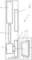
- the Fig. 1 shows a laser processing unit L, which has a control unit 1, a radiation source 2 that emits a laser beam 5, a beam shaping device 3 that shapes the laser beam 5 and a scanning device 4 that directs the laser beam 5 onto a platform 6.
- a carrier 7 is mounted above the platform and has corresponding means for applying a powder material to the platform 6 in a controlled manner in order to join it to a workpiece.
- the carrier 7 and, if necessary, also the scanning device 4 can be moved vertically away from the platform 6 or towards it.
- the laser processing unit L is also suitable for separating workpieces.
- the energy and focus are adjustable together with other beam properties of the laser beam 5, so that the laser processing unit L can be adapted to different materials.
- This property is used in the invention to provide not only the additive but also a subtractive manufacturing process in a single laser processing unit L.
- the control unit 1 the beam properties of the laser beam 5 can be adjusted in at least two settings. In a first setting, the laser beam 5 is designed in such a way that it joins the powder material, while in a second setting a workpiece that already exists or is made using the powder material is separated. This can be regulated, for example, via the radiation energy or the focus.
- the combination of scanning device 4 and carrier 7 is more precise in the Fig. 2
- the carrier 7 holds a material feed unit 8, which is movable parallel to the platform 6 along a linear axis via a motor contained in the carrier 7.
- a layer of powder material 9 is applied to the platform 6 and then joined by means of the laser beam 5.
- the plane in which the powder material 9 is joined or, if present, the workpiece is separated, is referred to as the application plane.
- the carrier 7 moves together with the material feed unit 8 and the mechanically coupled scanning device 4 in a build-up direction 10 perpendicularly away from the platform 6 before a further layer of powder material 9 is applied.
- the movement in the build-up direction 10 takes place according to an applied layer thickness of the powder material 9 and is typically dependent on its properties.
- the combination of carrier 7 and material feed unit 8 can be designed as a module, wherein the module is attached via a corresponding fastening device for assembly in the laser processing unit L.
- the material feed unit 8 further comprises an image sensor 19 with which the applied layer of powder material 9 is recorded.
- An algorithm executed in the control unit 1 evaluates the recorded images in order to monitor, for example, the homogeneity of the layer of powder material 9 or the condition of the workpiece.
- the material feed unit 8 is more precisely in Fig. 3 It comprises a material holder, here in the form of two powder chambers 11a, 11b, in which the powder material 9 is held.
- the powder material 9 is applied to the platform 6 in a controlled manner by means of a dosing unit 12, which is designed here as one roller per powder chamber 11a, 11b.
- the powder material 9 is smoothed by means of a transport system 13, which is designed here as a squeegee.
- An alternative to the squeegee would be another roller, which would additionally compact the powder material 9.
- a combination of both methods is also conceivable.
- An additional module 14a is located on the side of the material feed unit 8. This can be, for example, a vibration module, a heater or a combination of both.
- the vibration module ensures that the powder material 9 is applied evenly and the heater preheats the powder material 9 so that its processing is made easier.
- Such an additional module 14a can alternatively or additionally be integrated into the platform 6.
- a vibration module in the platform can also prevent powder accumulations, which can occur when producing workpieces that consist of a large number of layers.
- Fig. 4 The platform 6 of the laser processing unit L is shown from a bird's eye view in an alternative version.
- the platform 6 is supported by a The platform 6 is held in place by a displacement mechanism 15, which moves the platform 6 in two degrees of freedom in one plane. This allows much larger workpieces to be produced, since a larger work area is available.
- the platform 6 here has a further additional module 14b, which, similar to that already described above for the material feed unit 8, can be a heater, a vibration module or a combination of both.
- Fig. 5 shows an alternative design of the laser processing unit L, which is essentially identical to the structure of the Fig. 1 shown.
- the laser processing unit L has a chamber 17 with an entrance window 18 for the laser beam 5.
- the carrier 7 with the material feed unit 8 is located together with the platform 6 inside the chamber and is decoupled from the scanning device 4. After processing each layer, the carrier 7 moves here, while the scanning device 4 remains in position and the focus of the laser beam 5 is adjusted accordingly by means of the beam shaping 3.
- the scanning device can be moved linearly together with the carrier 7. However, for this to happen, it must also be located inside the chamber 17.
- This design offers several advantages. Firstly, it is possible to evacuate the chamber 17 or to fill it with a process gas in order to be able to use the laser processing unit L for a range of other powder materials 9 that require these conditions for their processing, or to further improve the precision of the manufacturing process. It is also possible to heat the chamber 17. This can be achieved by a separate heater, via the platform 6 or via the material feed unit 8, for example by means of the additional modules 14a, 14b described above.
- the chamber 17 additionally has a suction device 20 with which excess, unjoined powder material 9 is removed. This can be done with each completed layer or after a series of process steps when a sufficient amount of excess powder material 9 has accumulated on the platform 6.
- the suction device 20 can also be used in a laser processing device without a chamber 17.
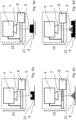
- Fig. 6a to 6d show the different types of processes that can be carried out with the laser processing unit L.
- Fig. 6a shows the separation of a workpiece 21, which is located on the platform 6.
- the scanning device 4 is moved together with the carrier 7 against the build-up direction 10 after removal of each layer towards the workpiece 21.
- the focus of the laser beam 5 can also be adjusted via the beam shaping 3.
- Fig. 6b shows another possibility for processing the workpiece 21.
- only the top layers or the top layer are removed or smoothed so that the workpiece 21 is polished.
- material properties of the workpiece 21 can be changed alternatively or additionally, for example by heat treatment or the like.
- the Fig. 6c shows the joining of the workpiece 21, which has already been described in more detail above.
- the joining of semi-finished products or components has not been discussed so far, which is described in the Fig. 6d
- a workpiece 21 is either provided or as shown in Fig. 6a shown, and then the powder material 9 is applied as already described above.
- the powder material 9 can have the same or a different material than the workpiece 21.
- a workpiece 21 can be manufactured from two different materials.
- a material feed unit 8 with two powder chambers 11a, 11b is used.
- a workpiece 21 is manufactured from a first material, which is located in the first powder chamber 11a.
- part of the workpiece 21 is separated.
- a second material is joined to the workpiece 21, or another part of the workpiece 21 made of the first material is joined.
- the workpiece 21 is polished and finished in this way.
- the steps described can be carried out one after the other as desired and material feed units 4 with more than two powder chambers 11a, 11b can be used.
- the manufacturing process can be interrupted and material from the powder chambers 11a, 11b can be exchanged by either re-equipping the material feed unit 4 or replacing it completely.
- This allows the laser processing unit L to process a wide range of materials and to produce highly complex workpieces 21, in particular multi-material systems.
Landscapes
- Engineering & Computer Science (AREA)
- Materials Engineering (AREA)
- Chemical & Material Sciences (AREA)
- Manufacturing & Machinery (AREA)
- Physics & Mathematics (AREA)
- Optics & Photonics (AREA)
- Mechanical Engineering (AREA)
- Toxicology (AREA)
- Health & Medical Sciences (AREA)
- General Health & Medical Sciences (AREA)
- Plasma & Fusion (AREA)
- Powder Metallurgy (AREA)
- Laser Beam Processing (AREA)
Applications Claiming Priority (1)
| Application Number | Priority Date | Filing Date | Title |
|---|---|---|---|
| DE102023114805.2A DE102023114805A1 (de) | 2023-06-06 | 2023-06-06 | Laserbearbeitungseinheit, Modul für eine Laserbearbeitungseinheit und Verfahren zur Herstellung eines Werkstücks |
Publications (2)
| Publication Number | Publication Date |
|---|---|
| EP4474136A2 true EP4474136A2 (fr) | 2024-12-11 |
| EP4474136A3 EP4474136A3 (fr) | 2025-02-12 |
Family
ID=91335093
Family Applications (1)
| Application Number | Title | Priority Date | Filing Date |
|---|---|---|---|
| EP24178363.8A Withdrawn EP4474136A3 (fr) | 2023-06-06 | 2024-05-28 | Unité d'usinage au laser, module pour une unité d'usinage au laser et procédé de fabrication d'une pièce |
Country Status (2)
| Country | Link |
|---|---|
| EP (1) | EP4474136A3 (fr) |
| DE (1) | DE102023114805A1 (fr) |
Citations (1)
| Publication number | Priority date | Publication date | Assignee | Title |
|---|---|---|---|---|
| DE10239369B4 (de) | 2002-08-28 | 2005-11-10 | Schott Ag | Verwendung eines pulverförmigen Werkstoffs zum selektiven Versintern |
Family Cites Families (6)
| Publication number | Priority date | Publication date | Assignee | Title |
|---|---|---|---|---|
| US5837960A (en) * | 1995-08-14 | 1998-11-17 | The Regents Of The University Of California | Laser production of articles from powders |
| WO2005089090A2 (fr) * | 2003-10-14 | 2005-09-29 | North Dakota State University | Appareil et procede de fabrication a ecriture directe et a forme libre |
| DE102004063489B3 (de) * | 2004-12-23 | 2006-08-31 | Greiwe, Reinhard, Dipl.-Ing. | Verfahren zur Herstellung eines Leichtbauelements aus Hohlkugeln |
| US20180345379A1 (en) * | 2017-05-31 | 2018-12-06 | General Electric Company | Apparatus and method for real-time simultaneous additive and subtractive manufacturing |
| CN109047762A (zh) * | 2018-08-31 | 2018-12-21 | 江苏大学 | 一种激光选区熔化与激光切割复合的增材制造方法 |
| JP2021041479A (ja) * | 2019-09-09 | 2021-03-18 | 株式会社スギノマシン | 加工機及び加工方法 |
-
2023
- 2023-06-06 DE DE102023114805.2A patent/DE102023114805A1/de active Pending
-
2024
- 2024-05-28 EP EP24178363.8A patent/EP4474136A3/fr not_active Withdrawn
Patent Citations (1)
| Publication number | Priority date | Publication date | Assignee | Title |
|---|---|---|---|---|
| DE10239369B4 (de) | 2002-08-28 | 2005-11-10 | Schott Ag | Verwendung eines pulverförmigen Werkstoffs zum selektiven Versintern |
Also Published As
| Publication number | Publication date |
|---|---|
| EP4474136A3 (fr) | 2025-02-12 |
| DE102023114805A1 (de) | 2024-12-12 |
Similar Documents
| Publication | Publication Date | Title |
|---|---|---|
| EP3099469B1 (fr) | Procédé et dispositif de commande améliorée de l'apport d'énergie dans un procédé de construction additive par génération de couches | |
| EP2864108B1 (fr) | Dispositif et procédé de fabrication par couches d'un objet tridimensionnel | |
| EP3362259B1 (fr) | Dispositif et procédé de fabrication d'un objet en trois dimensions | |
| EP3285988B1 (fr) | Procédé et dispositif de fabrication d'un objet tridimensionnel | |
| DE19853978C1 (de) | Vorrichtung für das selektive Laser-Schmelzen zur Herstellung eines Formkörpers | |
| DE102016211949A1 (de) | Beschichtungseinheit, Beschichtungsverfahren, Vorrichtung und Verfahren zum generativen Herstellen eines dreidimensionalen Objekts | |
| DE112013003448T5 (de) | Verfahren zum Fertigen eines dreidimensionalen Formgegenstands | |
| DE102016211952A1 (de) | Beschichtungseinheit, Beschichtungsverfahren, Vorrichtung und Verfahren zum generativen Herstellen eines dreidimensionalen Objekts | |
| WO2012019577A2 (fr) | Procédé de fabrication d'un composant tridimensionnel | |
| WO2018197443A1 (fr) | Homogénéisation de l'apport énergétique | |
| DE102015116886A1 (de) | Dreidimensionaler Drucker | |
| EP3216546A1 (fr) | Micro-forgeage pour un procédé de fabrication additive | |
| DE102007014968A1 (de) | Vorrichtung zur Herstellung von Gegenständen | |
| DE102017222645A1 (de) | Einrichtung zur Schutzgaszufuhr und Erwärmung und/oder Pulverzufuhr sowie Vorrichtung und Verfahren zur additiven Herstellung von Bauteilen und Bauteil | |
| DE102016203955B4 (de) | Verfahren zur Bereitstellung eines Steuerbefehlssatzes, generative Schichtbauvorrichtung, Steuereinrichtung und Computerprogramm | |
| EP3342583A1 (fr) | Procédé et dispositif de fabrication additive d'un objet tridimensionnel | |
| WO2012062253A2 (fr) | Dispositif pour produire, réparer et/ou remplacer une pièce structurale à l'aide d'une poudre durcissable sous l'action d'un rayonnement énergétique, ainsi qu'un procédé et une pièce structurale produite selon ce procédé | |
| WO2018197506A1 (fr) | Augmentation de la qualité de surface | |
| DE4439124C2 (de) | Verfahren und Vorrichtung zum Herstellen eines dreidimensionalen Objektes | |
| EP4474136A2 (fr) | Unité d'usinage au laser, module pour une unité d'usinage au laser et procédé de fabrication d'une pièce | |
| EP4045212A1 (fr) | Procédé de fonctionnement d'un dispositif de fabrication additive d'un objet tridimensionnel et procédé de création d'une fenêtre de traitement pour mettre en oeuvre ledit procédé | |
| EP2929962A1 (fr) | Procédé et dispositif destinés à améliorer la qualité de matière première pour des procédés de fabrication génératifs | |
| DE102017216411A1 (de) | Verfahren zur generativen Herstellung von Bauteilen sowie Vorrichtung zur Durchführung des Verfahrens | |
| DE102024124083A1 (de) | Einbringvorrichtung für ein additives Fertigungssystem, Fertigungssystem und Verfahren zur additiven Bauteilherstellung | |
| DE102017210345A1 (de) | Herstellungsvorrichtung und Verfahren zum generativen Herstellen eines Bauteils |
Legal Events
| Date | Code | Title | Description |
|---|---|---|---|
| PUAI | Public reference made under article 153(3) epc to a published international application that has entered the european phase |
Free format text: ORIGINAL CODE: 0009012 |
|
| STAA | Information on the status of an ep patent application or granted ep patent |
Free format text: STATUS: THE APPLICATION HAS BEEN PUBLISHED |
|
| AK | Designated contracting states |
Kind code of ref document: A2 Designated state(s): AL AT BE BG CH CY CZ DE DK EE ES FI FR GB GR HR HU IE IS IT LI LT LU LV MC ME MK MT NL NO PL PT RO RS SE SI SK SM TR |
|
| PUAL | Search report despatched |
Free format text: ORIGINAL CODE: 0009013 |
|
| AK | Designated contracting states |
Kind code of ref document: A3 Designated state(s): AL AT BE BG CH CY CZ DE DK EE ES FI FR GB GR HR HU IE IS IT LI LT LU LV MC ME MK MT NL NO PL PT RO RS SE SI SK SM TR |
|
| RIC1 | Information provided on ipc code assigned before grant |
Ipc: B33Y 30/00 20150101ALI20250107BHEP Ipc: B33Y 10/00 20150101ALI20250107BHEP Ipc: B29C 64/329 20170101ALI20250107BHEP Ipc: B29C 64/268 20170101ALI20250107BHEP Ipc: B29C 64/218 20170101ALI20250107BHEP Ipc: B29C 64/214 20170101ALI20250107BHEP Ipc: B22F 12/67 20210101ALI20250107BHEP Ipc: B22F 12/63 20210101ALI20250107BHEP Ipc: B22F 12/52 20210101ALI20250107BHEP Ipc: B22F 12/41 20210101ALI20250107BHEP Ipc: B22F 10/28 20210101ALI20250107BHEP Ipc: B29C 64/153 20170101AFI20250107BHEP |
|
| STAA | Information on the status of an ep patent application or granted ep patent |
Free format text: STATUS: THE APPLICATION IS DEEMED TO BE WITHDRAWN |
|
| 18D | Application deemed to be withdrawn |
Effective date: 20250813 |