EP4474599A1 - Telekommunikations- oder rundfunkturm mit modularer aussenschale - Google Patents
Telekommunikations- oder rundfunkturm mit modularer aussenschale Download PDFInfo
- Publication number
- EP4474599A1 EP4474599A1 EP24179747.1A EP24179747A EP4474599A1 EP 4474599 A1 EP4474599 A1 EP 4474599A1 EP 24179747 A EP24179747 A EP 24179747A EP 4474599 A1 EP4474599 A1 EP 4474599A1
- Authority
- EP
- European Patent Office
- Prior art keywords
- slats
- tower
- supporting structure
- peripheral
- outer casing
- Prior art date
- Legal status (The legal status is an assumption and is not a legal conclusion. Google has not performed a legal analysis and makes no representation as to the accuracy of the status listed.)
- Granted
Links
Images


Classifications
-
- E—FIXED CONSTRUCTIONS
- E04—BUILDING
- E04H—BUILDINGS OR LIKE STRUCTURES FOR PARTICULAR PURPOSES; SWIMMING OR SPLASH BATHS OR POOLS; MASTS; FENCING; TENTS OR CANOPIES, IN GENERAL
- E04H12/00—Towers; Masts or poles; Chimney stacks; Water-towers; Methods of erecting such structures
- E04H12/02—Structures made of specified materials
-
- H—ELECTRICITY
- H01—ELECTRIC ELEMENTS
- H01Q—ANTENNAS, i.e. RADIO AERIALS
- H01Q1/00—Details of, or arrangements associated with, antennas
- H01Q1/12—Supports; Mounting means
- H01Q1/1242—Rigid masts specially adapted for supporting an aerial
-
- E—FIXED CONSTRUCTIONS
- E04—BUILDING
- E04H—BUILDINGS OR LIKE STRUCTURES FOR PARTICULAR PURPOSES; SWIMMING OR SPLASH BATHS OR POOLS; MASTS; FENCING; TENTS OR CANOPIES, IN GENERAL
- E04H12/00—Towers; Masts or poles; Chimney stacks; Water-towers; Methods of erecting such structures
- E04H12/003—Access covers or locks therefor
Definitions
- the present invention relates to the technical field of towers, also called pylons or masts, and more particularly relates to a telecommunications or broadcasting tower comprising a modular outer casing.
- Towers, pylons or masts are commonly used in various fields, including telecommunications, cellular radiocommunication, terrestrial broadcasting, television broadcasting, energy or any other application requiring a slender vertical support structure of varying height. They are particularly intended to support telecommunications or radio broadcasting devices, including television. In some cases, these towers can also be used to support equipment supplying electrical energy, such as solar panels or wind turbines.
- integrated towers or monotube towers
- Monotube towers are built in metal from smooth helical metal tubes or faceted metal tubes forming modules that are then assembled between them to reach the desired height.
- the radio equipment, panel antennas, radio beams and signal converter boxes are integrated into the tube at the top of the tower, so as to not reveal any equipment, and openings, in front of which the antennas and beams are placed, are made in the tube to ensure the passage of waves.
- a low wind is sufficient to generate a Von Karman vortex path and vortex shedding at the rear of the tower, which generates vibrations that can cause fatigue leading to weld or anchor rod failures that can lead to a tower collapse.
- the logarithmic decrement of structural damping ⁇ s of 0.02 according to standards and technical literature is too low to eliminate or reduce the repeated displacements of the structure related to the Von Karman phenomenon.
- this type of tower integrates a liquid damper at its top to increase its logarithmic decrement of total damping, structural damping ⁇ s and dissipative damping ⁇ d, to dampen the vibrations.
- the addition of a damper or dissipative increases the initial cost of the tower, implies an additional cost for maintenance, and reduces the space available for the installation of equipment.
- modules of the monotube towers are bulky and require special transport, their production cost is high, their delivery time is long, and their carbon footprint is high, in particular due to the quantity of steel required for manufacturing.
- the closed structure of the monotube towers does not allow sufficient ventilation, so that solar radiation causes an increase in temperature inside the tower which can lead to premature failures of the integrated equipment.
- the present invention aims in particular to replace or adapt single-tube towers and to solve the problems indicated above by proposing a telecommunications or broadcasting tower comprising an outer casing.
- the present invention relates to a telecommunications/broadcasting tower comprising a supporting structure, the supporting structure being configured to be anchored to a foundation element, extend over a predefined height and comprise at least one receiving portion capable of receiving at least one radio equipment, such as a telecommunications antenna, characterized in that: the tower further comprises an outer casing consisting of at least one module, comprising: an outer skeleton fixed to the supporting structure, and a plurality of slats fixed to the outer skeleton, the assembly of the slats being configured to envelop the supporting structure at the level of the outer casing; the outer casing extends at least opposite the at least one receiving portion, such that the at least one radio equipment is received in an interior space of the tower defined by the outer casing, the outer casing comprising opposite the at least one radio equipment at least one of slats made of radio-transparent material and a cutout forming an opening in the outer casing, the plurality of slats being fixed to the outer casing
- Windward is understood to mean half a module cut by a vertical plane containing the median axis of the tower, i.e. the portion of a module directly receiving an air flow in the event of wind.
- This configuration makes it possible to provide a tower configured to receive at least one radio equipment that has an excellent aesthetic appearance that allows good integration into the landscape. Indeed, the slats are arranged to peripherally hide the supporting structure over at least part of the height of the tower. A tower with a "totem” appearance is thus obtained.
- an opening makes it possible to facilitate the passage of a signal originating from or intended for the at least one radio equipment, when the slats are composed of a radiotransparent material, for example wood, a polymer or a composite, or allows the passage of a signal, when the slats are composed of a radiopaque material, such as metal.
- a possible cover composed of a more radiotransparent material than that of the cut slats can be arranged in the opening, for example to mask the radio equipment or protect it.
- the radio equipment when the attenuation of radio waves from radio equipment placed behind the outer casing is low, or acceptable to the operator, the radio equipment will be completely hidden by the casing, without opening, and when the attenuation of radio waves from radio equipment behind the enclosure harms the quality of the broadcasts, the radio equipment is then placed in line with an opening formed by cutting slats around the edge of the radio equipment.
- the foundation element may be a permanent foundation element or a temporary foundation element.
- the supporting structure may, for example, be a metal lattice structure, a solid wood structure, a timber framed structure, or a metal tube.
- a solid wood structure may, for example, be a post, and that a timber framed structure is formed by assembling structural elements made of wood, for example solid wood or glued laminated wood. It may be specified that the use, for example, of a metal lattice structure or a timber framed structure as a supporting structure makes it possible to obtain a lighter tower with a lower carbon footprint than existing single-tube towers.
- a predefined gap is between two adjacent slats or between two adjacent groups of slats, each group of slats consisting of several slats (e.g. two or three slats) joined together without a gap between them. It will be understood that this configuration makes it possible to reduce or eliminate the formation of a Von Karman vortex path at the rear of the tower, in order to limit the vibrations of the tower.
- the slats may be fixed without any gap between them.
- the cross-sections of the slats may have different shapes, for example a parallelogram, rectangle, trapezoid, semicircle or portion of a circle shape.
- the predefined value of the logarithmic decrement of structural damping of the supporting structure is between 0.04 and 0.06, preferably between 0.045 and 0.055, and more preferably is 0.05.
- ordinary bolted lattice structures and timber framed structures generally have respective structural dampings of at least 0.05 and 0.1. These values may be sufficient to damp the tower in certain configurations of outer shell diameters, heights, natural frequencies, ground roughness classes and other parameters.
- the outer skeleton comprises at least two peripheral consoles, each peripheral console being fixed to the supporting structure so as to extend peripherally around the supporting structure
- the outer envelope comprises at least one module from among: a module comprising a first peripheral console, a second peripheral console peripheral spaced from the first peripheral console in a height direction of the tower, and slats of the plurality of slats having a first longitudinal end fixed to the first peripheral console and having a second longitudinal end fixed to the second peripheral console; and a module comprising a first peripheral console, a second peripheral console spaced from the first peripheral console in the height direction of the tower, a plurality of fixing bars having a first longitudinal end fixed to the first peripheral console and having a second longitudinal end fixed to the second peripheral console, and slats of the plurality of slats fixed to the fixing bars.
- a module without fixing bars is particularly suitable for arranging the slats in a direction parallel to a height direction of the tower, and that a module with fixing bars is particularly suitable for arranging the slats in a direction perpendicular to the height direction of the tower or inclined relative to it.
- At least one module comprises at least one third peripheral console arranged between the first peripheral console and the second peripheral console.
- the third peripheral console is configured to limit deformation slats, especially in windy conditions, and that it can be used as a simple stop or configured for fixing the slats to the third peripheral console.
- At least one of the peripheral consoles has a circular or polygonal exterior profile.
- the modules therefore preferably have a cylindrical shape. It will be understood, however, that the consoles may have other shapes, for example triangular or rectangular, so as to give the modules the desired shape.
- the outer casing comprises at least one of modules of different diameters and modules of different heights.
- each module is independent of the other modules, the modules being preferably attached in the height direction of the tower, to obtain a “totem” appearance and hide the supporting structure, with a gap provided between two consecutive modules allowing the slats to be worked.
- the peripheral consoles are configured such that at least one of the following conditions is met, so as to limit deformation of the outer casing in the event of wind: a peripheral edge of at least one of the first and second peripheral consoles is selectively movable according to a height direction of the tower, such that a tensile stress is selectively applied to the slats, if applicable to the fixing bars; a peripheral edge of at least one of the first and second peripheral consoles is pivotally mounted, so as to be able to selectively impart a frustoconical external shape to the at least one peripheral console, such that the slats, if applicable the fixing bars, are selectively tensioned and bent towards an exterior of the tower; and a peripheral edge of at least one of the first and second peripheral consoles is fixed and inclined to impart a frustoconical external shape to the at least one peripheral console, such that the slats, if applicable the fixing bars, are bent towards an exterior of the tower during assembly.
- first and second peripheral consoles configured to apply a prestress may optionally be combined with a third peripheral console as described above, optionally configured for fixing the slats on the third peripheral console.
- the outer envelope further comprises at least one point connecting element configured to connect two neighboring slats, where appropriate across a predefined interval, so as to limit deformation of said slats in the event of wind.
- the point connecting elements can be configured to connect two neighboring slats arranged without a predefined gap between them, or to connect two neighboring slats arranged with a predefined gap between them.
- Each point connecting element can for example be a staple, a point insert, or a combination of a point insert and at least one of a staple, a nail and a screw.
- the point inserts are preferably introduced after bending the slats obtained by any means, the force having allowed the bending of the slats possibly being released after the insertion of the point inserts. It will however be understood that the dimensions of the point inserts can be chosen to allow their direct placement, without bending the slats, the point inserts then preferably being connected to the neighboring slats, for example using staples, nails or screws.
- the foundation element is selected from a foundation element disposed in the ground, a foundation element disposed on the ground and a foundation element disposed on a building roof.
- the outer envelope extends over the entire height of the tower.
- the outer envelope can extend over only a portion of the height of the tower.
- each slat has a cross-section having the shape of a non-rectangular parallelogram and all the slats are assembled successively in the same direction over the entire periphery of the at least one module, such that, in the event of wind, an air inlet is facilitated on a first lateral portion of a windward face of the at least one module and is limited on a second lateral portion of the windward face of the at least one module, thus forming an asymmetrical air flow around the at least one module and reducing at least the formation of a Von Karman vortex path.
- the plurality of slats comprises at least one of: a wooden slat, a slat comprising a recycled polymer, a slat comprising a recyclable polymer and a slat made of composite material.
- the choice of material used for the slats can in particular make it possible to significantly reduce the steel weight of the tower and its carbon footprint. It will be understood, however, that metal slats, for example steel or aluminium, can also be used on certain parts of the tower.
- the plurality of slats are treated to limit water absorption of the slats and ensure a humidity level in the slats of less than 20% by mass, so as to limit attenuation, induced by the slats, of a signal originating from or intended for the at least one radio equipment.
- the slats can also be painted or varnished, and that reducing the humidity level can also extend the life of the slats.
- a width of at least one predefined interval is constant along said at least one predefined interval.
- all predefined intervals are identical.
- all the elements of the supporting structure and the outer shell have dimensions and weights allowing transport by a conventional vehicle and assembly of the tower without the use of a lifting crane.
- the invention also relates to a method of leveling a tower according to the invention, after an initial assembly, characterized in that the method comprises at least at least one of the following steps: a) fixing reinforcing elements to the supporting structure, without first dismantling the supporting structure, to reinforce the supporting structure, such that a load-bearing capacity of the supporting structure is increased, without changing its external appearance; b) optionally, adding additional chords to the supporting structure, without first dismantling the supporting structure, to raise the supporting structure beyond the predefined height; fixing at least one additional peripheral console to the supporting structure; if necessary, fixing a plurality of additional fixing bars to the at least one additional peripheral console; and fixing a plurality of additional slats to the at least one additional peripheral console, or if necessary to the additional fixing bars; c) dismantling slats and peripheral consoles of the outer shell, without first dismantling the supporting structure; and replacing said peripheral consoles and reassembling new slats, the new slats being identical
- the method of upgrading the tower is permitted because for the present invention the outer shell and the supporting structure are independent of each other, which makes it possible to modify one independently of the other. It will also be understood that the method of upgrading the tower allows in particular an adaptation throughout the life of the tower, for example in cases where radio equipment arranged in the tower must be replaced by radio equipment of different dimensions, or of different weights, or must be placed at another location on the tower or be oriented in another direction.
- the invention also relates to a method for retrofitting an existing telecommunications/broadcasting tower comprising a supporting structure, characterized in that the method comprises a step consisting of: adding to the existing tower an outer casing consisting of at least one module and comprising an outer skeleton and a plurality of slats, said step comprising the sub-steps consisting of: fixing the outer skeleton to the supporting structure, and fixing the plurality of slats to the outer skeleton, such that the assembly of the slats is configured to envelop the supporting structure at the level of the outer casing; the outer casing extending at least opposite a receiving portion of the tower capable of receiving at least one radio equipment, such that the at least one radio equipment is received in an interior space defined by the casing.
- the outer casing comprising opposite the at least one radio equipment at least one of slats made of radio-transparent material and a cutout forming an opening in the outer casing, the plurality of slats being fixed to the outer skeleton such that if the logarithmic decrement of structural damping of the supporting structure is less than a predefined value, for at least the module(s) opposite the at least one receiving part, a projected surface, on a median vertical plane of the tower, of a windward face of the at least one module defined by said median vertical plane is, due to through openings formed by predefined intervals formed between the slats, at least 10% less than the projected surface of an equivalent full windward face, to at least reduce the formation of a Von Karman vortex alley.
- this retrofit modification method makes it possible in particular to provide sufficient space to accommodate radio equipment and to mask the radio equipment while reducing the formation of a Von Karman vortex alley if the logarithmic decrement of structural damping of the supporting structure is insufficient.
- the predefined value of the logarithmic decrement of structural damping of the supporting structure is preferably between 0.04 and 0.06, more preferably between 0.045 and 0.055, and more preferably is 0.05.
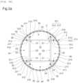
- the tower 1 comprises a supporting structure 2 extending over a predefined height and configured to be anchored to a foundation element F, and a modular outer shell 3 fixed to the supporting structure 2.
- the supporting structure 2 may for example be fixed to the foundation element F using anchor rods, or a sealing section, i.e. a structure similar to that of the tower 1 and the height of the foundation element F, cast into the foundation element F, or even plates and bolts in the case where the foundation element F is a temporary foundation element F.
- the foundation element F is a rectangular concrete element placed in the ground. It will be understood, however, that the structure and positioning of the foundation element F may vary depending on the use of the tower 1. Alternatively, the foundation element F could, for example, be placed on the roof of an existing building, particularly in the case of a location in a city.
- the supporting structure 2 is a metal lattice structure, for example made of steel or aluminum or other metal alloy, comprising a plurality of vertical members 21, horizontal crosspieces 22 and diagonals 23 assembled together, for example by bolting, riveting or welding, to form the supporting structure 2.
- the members 21 have the shape of an angle iron with an “L” cross section. It will be understood, however, that the members 21 may take other shapes, for example round, square or circular tubes, or bars, and that the same is true for the crosspieces 22 and the diagonals 23.
- the members 21 are assembled to form four uprights, such that the cross-sectional profile of the metal lattice structure is square. It will be understood, however, that the supporting structure 2 could have a triangular profile, or another shape.
- the supporting structure 2 may comprise wooden structural elements in combination with or replacing the metal structural elements.
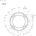
- the supporting structure 2 may for example be a massive wooden structure 24, for example a post as shown in the Figure 2b , a timber framed structure, formed by assembling structural wooden elements, for example solid wood or glued laminated timber, or a metal tube.
- the supporting structure 2 comprises a receiving part 25, arranged at a top of the supporting structure 2, configured to receive radio equipment E.
- Radio equipment E means any transmitting and/or receiving equipment, for example a telecommunications antenna, a panel antenna, a radio beam, a remote radio unit (designated in English by the acronym RRU for Remote Radio Unit) or a remote radio head (designated in English by the acronym RRH for Remote Radio Head).
- the tower 1 may comprise several receiving parts 25 and/or that each receiving part 25 may be configured to receive one or more radio equipment E. It will also be understood that the receiving part 25 is not necessarily arranged at the top of the tower 1, but that the higher the receiving part 25 is arranged, the easier it is to transmit and receive the radio equipment E.
- the tower 1 may have several receiving parts 25 arranged one above the other on the tower 1, each preferably but not necessarily corresponding to a module 36 of the tower 1.
- the receiving portion 25 is further configured to receive converter boxes. signal configured to work with E radio equipment.
- the tower 1 may optionally be configured to receive one or more photovoltaic panels configured to power the integrated equipment of the tower 1 or to power an electrical network, for example the electrical network of a building or a city.
- the top of the tower 1 could also be configured to receive one or more wind turbines, with a vertical or horizontal axis of rotation.
- the modular outer casing 3 is configured to extend at least opposite the reception part 25, so as to define an interior space 34 in which the radio equipment E is received, such that the latter is at least partially concealed and not visible to a person located outside the tower 1, which in particular improves the aesthetic appearance of the tower 1.
- the outer envelope 3 preferably extends over the entire height of the tower 1, in particular to further improve the aesthetic appearance of the tower 1 and facilitate its integration into the landscape.
- the modular outer envelope 3 is made up of at least one module 36 and comprises an outer skeleton 31 configured to be fixed to the supporting structure 2, and a plurality of slats 32 configured to be fixed to the skeleton. exterior 31.
- the radio equipment E may be fixed to the supporting structure 2 or to the external skeleton 31, preferably by means of a support.
- the fixing may be carried out by any means, for example by bolting.
- the slats 32 can be fixed without a gap between them over at least part of the height of the outer envelope 3.
- the lattice-type structures assembled by ordinary bolts and the wooden framed structures have respective structural dampings of at least 0.05 and 0.1. These values may be sufficient to damp the tower 1 in certain configurations of diameters of the outer envelope 3, heights, natural frequencies, classes of roughness of the ground and other parameters.
- the slats 32 are fixed to the external skeleton 31 in such a way that if the logarithmic decrement of structural damping of the supporting structure is less than a predefined value, for at least the module(s) 36 facing the at least one receiving part 25, a projected surface, on a median vertical plane of the tower 1, of a windward face of the at least one module 36 defined by said median vertical plane is, due to through openings formed by intervals predefined 33 formed between the slats 32, at least 10% less than the projected surface of an equivalent full wind face.
- predefined intervals 33 in the upper third of the outer envelope 3 may be sufficient to reduce the formation of a Von Karman vortex alley.
- Windward is understood to mean half a module cut by a vertical plane containing the median axis of the tower, i.e. the portion of a module directly receiving an air flow in the event of wind.
- the predefined value of the logarithmic decrement of structural damping of the supporting structure is preferably between 0.04 and 0.06, more preferably between 0.045 and 0.055, and more preferably is 0.05.
- each slat 32 is configured to be attached to the outer skeleton 31 such that a plurality of predefined gaps 33 are formed in the outer shell 3, each predefined gap 33 extending longitudinally between two neighboring slats 32 spaced apart from each other, so as to limit the formation of a Von Karman vortex path at the rear of the tower 1 in the event of wind.
- a predefined interval 33 is formed between any pair of two neighboring slats 32, and all the predefined intervals 33 have the same, constant width. over the entire length of the predefined interval 33.
- the predefined intervals 33 could also have different widths from each other, the distribution of the predefined intervals 33 could be regular or irregular on the periphery of the outer casing 3, or the predefined intervals 33 could have different shapes, for example due to a non-parallel arrangement of the slats 22, for example in a “V” shape.
- the assembly of the slats 32 of the outer casing 3 thus forms, peripherally, a succession of slats 32 and predefined intervals 33.
- such an assembly of the slats 32 makes it possible to at least reduce the formation of a Von Karman vortex path which could normally occur in the case of a slender vertical structure such as a tower 1 according to the present invention, by creating an irregular and non-smooth outer surface for the outer casing 3 and by allowing the passage of air flows through the predefined intervals 33 and through the tower 1.
- a tower 1 according to the invention therefore does not need to comprise a liquid damper at its top. It will be understood that part of the air which enters the tower through predefined intervals 33 exits on the other side through other predefined intervals 33, and that another part of the air can also exit through the top of the tower 1 when an opening at the top is left free.
- all the slats 32 have a cross-section having the shape of a rectangle.
- This shape of slat 32 has in particular the advantage of facilitating the manufacture of the slats 32.
- the cross-section of the slats 32 could, as a variant, have another shape, for example a shape of a parallelogram, a trapezoid, a semi-circle or a portion of a circle.
- a modification of the shape of the cross-section of the slats 32 makes it possible to vary the quantity of air entering the outer envelope 3, without modifying the distribution of the slats 32.
- FIG. 8 presents a variant of a module 36 for which the slats 32 have a cross-section having the shape of a non-rectangular parallelogram and for which all the slats 32 are assembled successively in the same direction over the entire periphery of the module 36, such that, in the event of wind, an air inlet is facilitated on a first lateral portion of a windward face of the module 36 and is limited on a second lateral portion of the windward face of the module 36, thus forming an asymmetrical air flow around the module 36 and reducing at least the formation of a Von Karman vortex path.
- the passage of air flows through the predefined intervals 33 further allows ventilation of the tower 1 which makes it possible to avoid overheating of the radio equipment E and to prevent premature malfunctions thereof.
- the use of certain materials for the slats 32, for example wood makes it possible to reduce the increase in heat inside the tower 1 due to solar radiation.
- the distal or top end and the proximal end of the outer casing 3 can be left free or be closed, for example using additional slats 32, for example to protect the radio equipment E from direct solar radiation, and/or by a bird-proof mesh or net. It will be understood that, preferably, the top end of the outer casing 3 is not completely obstructed, so as to allow air to be evacuated through the top of the tower 1.
- the outer casing 3 is configured to allow signals from or intended for the radio equipment E to pass through.
- the outer casing 3 comprises, opposite the radio equipment E, slats 32 made of radio-transparent material configured to allow the passage of signals.
- Radio-transparent material is understood to mean a material whose attenuation measured in decibels is low, for example less than 5 dB.
- the slats 32 made of radio-transparent material are preferably made of wood but may also be composed of other materials, for example a recycled polymer, a recyclable polymer or a composite material, comprising for example a matrix made of recycled or recyclable polymer and reinforcing fibers, for example plant fibers.
- the wood may for example be Douglas fir, pine, larch or any other type of wood.
- slats 32 made of wood or recycled material makes it possible in particular to reduce the carbon footprint of tower 1.
- the slats 32 can optionally be painted or varnished in order to improve the integration of tower 1 into the landscape.
- slats 32 of different shades can be mixed, ordered, or arranged in the form of a range of shades.
- the slats 32 can for example be treated to limit water absorption by the slats 32 and guarantee a humidity level in the slats 32 of less than 20% by mass, preferably less than 10% by mass, so as to limit attenuation, induced by the slats 32, of signals coming from the radio equipment E, or intended for the latter.
- the wood can be treated so as to reduce the level of hydrophilic compounds in it.
- the slats 32 can also be painted or varnished in order to reduce water absorption. It will be understood that a reduction in water absorption also makes it possible to increase the service life of the slats 32.
- the other slats 32 that is to say the slats 32 which are not directly arranged opposite a radio equipment E, can be composed, as desired, of a radio-transparent material or a radio-opaque material, for example a metal, for example steel or aluminum.
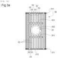
- the outer casing 3 comprises, opposite the radio equipment E, an opening 35 made by cutting the slats 32.
- the opening 35 can have a circular shape, as shown in the Figure 3a , a rectangular shape, as shown in the Figure 3b , or any other shape, for example oval or triangular.
- the outer casing 3 further comprises retaining bars 351, placed inside or outside, for fixing the longitudinal ends of the slats 32, cut to form an opening 35, to adjacent uncut slats 32, for example to prevent movement of the free longitudinal ends and deformation of the cut slats 32.
- one or more radio equipments E can be arranged opposite each opening 35.
- a tower 1 can be configured to receive one or more radio equipment E facing slats 32 made of radio-transparent material, and one or more radio equipment E facing one or more openings 35.
- each opening 35 is further closed by a cover 352 made of radio-transparent material, for example wood, polymer or composite, so as to at least partially mask the radio equipment E arranged opposite. It will however be understood that as a variant the opening 35 can be left free.
- openings 35 makes it possible to facilitate the passage of signals when the slats 32 are composed of a radio-transparent material, for example wood, a polymer or a composite, and that a possible cover 352 is then composed of a more radio-transparent material than that of the cut slats 32; or allows the passage of signals, when the slats 32 are composed of a radio-opaque material, such as metal.
- a radio-transparent material for example wood, a polymer or a composite
- a possible cover 352 is then composed of a more radio-transparent material than that of the cut slats 32; or allows the passage of signals, when the slats 32 are composed of a radio-opaque material, such as metal.
- the outer skeleton 31 comprises a plurality of peripheral consoles 311.
- the peripheral consoles are preferably made of metal, for example steel, but may also be made of wood, composite or comprise a combination of metal, wood and composite.
- Each peripheral console 311 comprises a peripheral edge 312, configured to extend in use around the supporting structure 2, and fixing lugs 313, extending radially from the peripheral edge 312, configured to fix the peripheral console 311 to the supporting structure 2.
- each peripheral edge 312 is formed by an assembly of several parts, in particular to facilitate the mounting of the peripheral consoles 311 on the supporting structure 2.
- the fixing lugs 313 may be fixed by any means to the supporting structure 2, for example by welding, but are preferably fixed by a means capable of facilitating disassembly, such as for example by screwing, bolting or riveting.
- the fixing lugs 313 of the peripheral consoles 311 are fixed to the members 21 of the supporting structure by bolting on brackets of fixing 211 welded to the members 21, while according to the embodiment shown in the Figure 2b the fixing lugs 313 are fixed to the solid wooden structure 24 by means of a fixing collar tightened around the solid wooden structure 24.
- the fixing lugs 313 could also be fixed to the supporting structure 2 by screwing or bolting directly into the supporting structure 2.
- the external profile of the peripheral consoles 311 is circular in shape.
- the peripheral edges 312 of the peripheral consoles 311 can be formed by successive folding, such that the external profile of the peripheral consoles 311 has a polygonal shape, preferably regular, and has facets.
- each facet receives a slat 32 and the predefined intervals 33 are formed at the angles between the facets.
- each facet can be configured to receive several slats 32 glued to each other or spaced apart, a facet can be configured not to receive a slat 32 so as to form a predefined interval 33, or again, for the same peripheral console 311, some facets may be configured to receive more slats 32 than other facets.
- the peripheral consoles 311 may also have another shape, for example a triangular, oval or rectangular shape.
- the slats 32 are directly fixed to the peripheral edges 312 of the peripheral consoles 311, preferably by bolting.
- a first longitudinal end is fixed to a first peripheral console 311 and a second longitudinal end is fixed to a second peripheral console 311 offset relative to the first peripheral console 311 according to the height direction of the tower 1.
- an assembly comprising the first and second peripheral consoles 311 connected by slats 32 forms a module 36 of the outer casing 3.
- this method of fixing the slats 32 to the peripheral consoles 311 is particularly suitable for positioning the slats 32 in a direction parallel to a height direction of the tower 1.
- the slats 32 can be fixed to the peripheral consoles 311 by means of fixing bars.
- the fixing bars are preferably made of metal but can also be made of wood or composite.
- the peripheral consoles 311 have the same structure as that described above, however the outer skeleton 31 further comprises fixing bars, a first longitudinal end of which is fixed to a peripheral edge 312 of a first peripheral console 311, for example by welding, riveting or bolting, and a second longitudinal end of which is fixed to a peripheral edge 312 of a second peripheral console 311 offset relative to the first peripheral console 311 in the height direction of the tower 1. Then the slats 32 are fixed to the fixing bars, preferably by bolting or by means of clamps.
- an assembly comprising the first and second peripheral consoles 311 connected by fixing bars to which slats 32 are fixed form a module 36 of the outer casing 3.
- This method of fixing the slats 32 to the peripheral consoles 311 is particularly suitable for positioning the slats 32 in a direction perpendicular to the height direction of the tower 1, the predefined intervals 33 then also extending in a direction perpendicular to the height direction of the tower 1, i.e. horizontally in use.
- the slats 32 preferably have an arched shape to give a cylindrical external shape to the external envelope 3.
- the slats 32 can be fixed by any means to the external skeleton 31, but are preferably fixed by bolting, riveting or screwing, in particular to allow easy disassembly of the slats 32.
- the slats 32 may be fixed to the outer skeleton 31 so as to allow disassembly of the slats from inside the tower 1 or from outside the tower 1, for example by fixing the slats 32 on an inner side of the peripheral consoles 311, where appropriate fixing bars, or on an outer side of the peripheral consoles, where appropriate fixing bars.
- a tower 1 according to the invention comprises at least one module 36 arranged opposite each receiving part 25, generally in the upper part. However, preferably and as shown in the Figure 1 , tower 1 comprises several modules 36 arranged over the entire predefined height of the supporting structure 2.
- each module 36 of the outer casing 3 is independent, such that the modules 36 may have different diameters and heights from each other.
- the modules 36 may for example have heights of 2 m, 4 m or 6 m, for example depending on the height of the radio equipment E arranged opposite.
- modules with a height of between 1 m and 2 m may be provided to set up radio beams with a height of between 0.3 m and 1.20 m, these are generally placed at the top of the tower 1
- 4 m modules may be provided to receive 3G, 4G or 5G panels with a height of between between 1 m and 3 m
- 6 m modules can be provided to install radio beams in the upper part, panel antennas and other equipment below.
- the modules 36 are preferably attached to the height of the tower 1, with a clearance provided between two consecutive modules 36 for the work of the slats 32, and preferably have a constant diameter, in order to cover and hide the supporting structure 2 and obtain a tower 1 with a “totem” tower appearance.
- the diameter of a module is chosen according to the dimensions of the radio equipment E arranged opposite, so that the interior space 34 defined between the module and the supporting structure 2 makes it possible to receive the radio equipment E.
- a tower 1 according to the present invention can comprise both modules 36 without fixing bars and modules 36 with fixing bars.
- the slats 32, where appropriate fixing bars, connecting the first peripheral console 311 to the second peripheral console 311 are of great length, such that they can deform in the event of wind.
- the invention provides several technical solutions.
- a module may comprise a third peripheral console 311, arranged between the first peripheral console 311 and the second peripheral console 311.
- This third peripheral console 311 may be configured to simply serve as a stop preventing further deformation of the slats 32, if applicable the fixing bars, towards the inside of the tower 1, or may be configured for fixing the slats 32, if applicable the fixing bars, to the third peripheral console 311.
- each module could comprise a fourth, a fifth and an n-th peripheral console 311 arranged between the first and second peripheral consoles 311, as required, and so as not to interfere with the arrangement of the radio equipment E.
- the fixing lugs 313 of the peripheral consoles 311 are fixedly fixed to the supporting structure 2, such that the fixing lugs 313 and the fixing brackets 211 are integral.
- the peripheral edge 312 of the peripheral consoles 311 is inclined, such that the peripheral consoles 311 have a truncated external shape.
- the peripheral consoles 311 are arranged such that the slats 32, if applicable the fixing bars, fixed to the peripheral edges 312 of the peripheral consoles 311 are caused to be bent towards an exterior of the tower 1.
- the fixing lugs 313 of the peripheral consoles 311 are pivotally mounted on the supporting structure 2, for example by using a single fixing bolt 315 per fixing lug 313 or by using a dedicated pivot axis.
- the outer skeleton 31 further comprises biasing devices 314 mounted between the supporting structure 2 and the peripheral edge 312 of the peripheral consoles 311, the biasing devices 314 being configured to apply a force to the peripheral edge 312, so as to exert tension and bending of the slats 32.
- the biasing devices 314 apply a pressure force, such that the slats 32 are bent towards an exterior of the tower 1.
- each peripheral edge 312 is preferably formed by an assembly of several parts, in particular to facilitate tensioning of the slats 32.
- the biasing devices 314 are of the screw type, for example screw turnbuckles comprising a threaded tube and one or two threaded rods engaged with the threaded tube, such that a pressing force can be selectively applied to the peripheral edge 312 by screwing, or unscrewing, the biasing device 314.
- the biasing devices solicitation 314 may, alternatively, have another structure and may for example be jacks.
- the biasing devices 314 may be operated manually or via a drive system, for example an electric motor, a hydraulic pump or a pneumatic compressor, possibly controlled remotely by wire or wireless means.
- a drive system for example an electric motor, a hydraulic pump or a pneumatic compressor, possibly controlled remotely by wire or wireless means.
- fixing lugs 313 can be fixedly mounted to the supporting structure 2 and the peripheral edges 312 can be pivotally mounted on the fixing lugs 313.
- the peripheral consoles 311 can also be configured to allow a displacement of the peripheral edges 312 in sliding in the height direction of the tower 1, and the stressing devices 314 can be configured to cause a displacement of the peripheral edges 312 in the height direction of the tower 1, so as to separate the first and second peripheral consoles 311, such that a tensile stress is selectively applied to the slats 32. It will also be understood that for each module 36, the prestresses are applied once all the slats 32 are mounted, and that the peripheral consoles 311 and the stressing devices 314 can be configured to allow a stress in the height direction of the tower 1 and a bending to be combined.
- prestressing the slats 32 in outward bending or in tension, makes it possible to reduce subsequent deformations of the slats 32 induced by the wind, and in particular beating against the radio equipment, damaging it and generating noise.
- slats 32 of arched shape could be used instead of the slats 32 placed in bending, so as to limit deformations of the slats 32 in the event of wind.
- peripheral brackets 311 and biasing devices 314 can be used with modules 36 comprising fixing bars, so as to apply flexion or traction to the fixing bars, so as to reduce deformations of the fixing bars in the event of wind.
- arcuate-shaped fixing bars could be used instead of fixing bars placed in flexion, so as to limit deformations of the fixing bars in the event of wind.
- an operating clearance is provided between two successive modules 36 of the tower 1, such that movements of the peripheral edges 312 are permitted without contact between the modules 36, for example a clearance of 20 mm between two successive modules 36 can be used.
- the outer casing 3 further comprises punctual connecting elements 37 in the form of punctual inserts introduced into the predefined intervals 33 so as to punctually connect two neighboring slats 32.
- the point inserts are preferably introduced at a central portion of the slats 32, but can also be distributed at several locations along the predefined intervals 33.
- the slats 32 are first bent, such that this embodiment can be combined with the embodiment comprising peripheral brackets 311 for bending the slats 32.
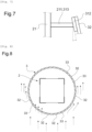
- the point inserts can also be used with the so-called fixed type embodiment shown in Figure 7 .
- the slats 32 may be bent by another means and then released after introduction of the point inserts 37.
- the point inserts may have dimensions which allow insertion of the point inserts in predefined intervals 33 without bending the slats 32.
- the point inserts are then preferably connected to the neighboring slats 32, for example using staples or screws.
- the point connecting elements 37 may be staples.
- point connecting elements 37 are configured to connect two adjacent neighboring slats or two neighboring slats separated by a predefined interval 33.
- FIG. 6 shows a sectional view of the point inserts 37 introduced between the slats 32.
- the point inserts 37 are introduced in all the predefined intervals 33 and at longitudinally aligned positions in the predefined intervals 33. It will be understood that as a variant the point inserts 37 can be introduced only in certain predefined intervals 33, or be offset longitudinally in the predefined intervals 33.
- all the constituent elements of the tower 1, in particular the elements of the supporting structure 2 and of the outer shell 3, preferably have dimensions and weights chosen to allow them to be easily transported, for example using a conventional transport truck, such that several transports are not necessary when assembling the tower 1.
- the dimensions and weights of the elements are preferably chosen to allow their handling without the use of a lifting crane, for example using manual lifting means.
- a tower 1 according to the present invention has the advantage of requiring much less steel than an existing single-tube tower, which in particular makes it possible to significantly reduce the carbon footprint of the tower 1 and to reduce its weight.
- a tower 1 according to the invention can be equipped with access ladders but also with work platforms allowing access and maintenance of radio equipment E from inside the tower 1.
- the present invention allows for continuous evolution of tower 1 at lower cost throughout its life.
- the present invention therefore also relates to a method of upgrading a tower 1 according to the invention, comprising one or more of the steps described below.
- One step is to fix reinforcing elements to the supporting structure 2, without first dismantling the supporting structure 2, to reinforce the supporting structure 2, such that a bearing capacity of the supporting structure 2 is increased without changing the external appearance thereof.
- the reinforcing elements may for example be additional members 21 added to the supporting structure 2, for example to double the members 21 already mounted. It will be understood that the reinforcing elements can also replace structural elements of the supporting structure 2, for example members 21, crosspieces 22 or diagonals 23. The reinforcing elements can be added over the entire predefined height of the supporting structure 2, or only to a lower part of the supporting structure 2. It will also be understood that the reinforcing elements can be configured to be anchored to the foundation element F to which the supporting structure 2 is anchored.
- Another step is to optionally add additional members 21 to the supporting structure 2, without first dismantling the supporting structure 2, to raise the supporting structure 2 beyond the predefined height; attach at least one additional peripheral console 311 to the supporting structure; if applicable, attach a plurality of additional fixing bars to the at least one additional peripheral console 311; and attach a plurality of additional slats 32 to the at least one additional peripheral console 311, or if applicable to the additional fixing bars.
- this step makes it possible to add additional modules 36 to the supporting structure 2, possibly after having raised the supporting structure 2, for example to place the radio equipment E of tower 1 at a higher height or to add additional radio equipment E.
- Another step consists in dismantling slats 32 and peripheral consoles 311 from the outer casing 3, without first dismantling the supporting structure 2; and replacing said peripheral consoles 311 and reassembling new slats 32, the new slats 32 being identical to or different from the dismantled slats 32.
- the new peripheral consoles 311 may have a different diameter than the dismantled peripheral consoles 311, so as to form modules 36 of different diameter.
- the slats 32, and where appropriate the fixing bars, may also have a different length, so as to form modules 36 of different length.
- Another step is to replace slats 32 of the outer casing 3, without first dismantling the supporting structure 2, for example to replace damaged slats 32 or to change the material of the slats 32.
- the structure of the outer casing 3 described above allows easy and low-cost replacement of the slats 32.
- Another step is to cut slats 32, without first dismantling the supporting structure, to form an opening 35 in the outer casing 3, and optionally, add retaining bars 351 to fix the longitudinal ends of said cut slats 32 to adjacent uncut slats 32.
- This step makes it possible, for example, to form an opening 35 in the outer casing 3 when it is detected that the slats 32 are reducing too much important the propagation of signals from radio equipment E located opposite, or when new radio equipment E is installed in tower 1.
- the tower 1 according to the invention therefore allows for adaptation, for example in cases where radio equipment E arranged in tower 1 must be replaced by radio equipment E of different dimensions or placed in another location or oriented in another direction.
- each of the steps described above can be carried out without first dismantling the supporting structure 2, such that the tower 1 does not need to be removed and the radio equipment E installed in the tower 1 can continue to operate normally, without interruption of transmissions during the performance of the steps.
- One or more modules 36 of the outer casing 3 hindering the performance of a step may possibly be temporarily removed and then reassembled on the tower 1 once the step is completed.
- the invention further relates to a method for retrofitting an existing telecommunications/broadcasting tower comprising a supporting structure 2, comprising a step of adding to the existing tower an outer shell 3 consisting of at least one module 36 and comprising an outer skeleton 31 and a plurality of slats 32.
- Said step comprising the sub-steps of fixing the outer skeleton 31 to the supporting structure 2, and fixing the plurality of slats 32 to the outer skeleton 31, such that the assembly of the slats 32 is configured to wrap the supporting structure 2 at the level of the outer envelope 3.
- the outer casing 3 extends at least opposite a reception portion 25 of the tower capable of receiving at least one radio equipment E, such that the at least one radio equipment E is received in an interior space 34 defined by the outer casing 3, the outer casing 3 comprises opposite the at least one radio equipment E at least one of slats 32 made of radio-transparent material and a cutout forming an opening 35 in the outer casing 3.
- the plurality of slats 32 are attached to the outer skeleton 31 such that if the logarithmic decrement of structural damping of the supporting structure is less than a predefined value, for at least the module(s) 36 facing the at least one receiving portion 25, a projected surface, on a median vertical plane of the tower 1, of a windward face of the at least one module 36 defined by said median vertical plane is, due to through openings formed by predefined gaps 33 formed between the slats 32, at least 10% less than the projected surface of an equivalent full windward face, to at least reduce the formation of a Von Karman vortex alley.
- this retrofit modification process can, for example, be applied in the case of existing towers having as their supporting structure a metal lattice structure, a massive wooden structure, a wooden frame structure, or a tube metal, with or without damping device.
- a solid wooden structure can for example be a post, and that a wooden framed structure is formed by assembling structural elements made of wood, for example solid wood or glued laminated wood.
- the invention is not limited by the number of modules on a tower, by the intervals between the slats, which depend on the structure of the tower and the environment in which it is installed.
- the intervals between the slats may be identical or different within a module, identical or different between two adjacent modules.
- the modules may have different sizes, and cover all or part of the tower, generally at least the upper part of the tower intended to receive the equipment, without the invention being limited in this regard.
Landscapes
- Engineering & Computer Science (AREA)
- Architecture (AREA)
- Life Sciences & Earth Sciences (AREA)
- Chemical & Material Sciences (AREA)
- Materials Engineering (AREA)
- Wood Science & Technology (AREA)
- Civil Engineering (AREA)
- Structural Engineering (AREA)
- Buildings Adapted To Withstand Abnormal External Influences (AREA)
- Support Of Aerials (AREA)
- Casings For Electric Apparatus (AREA)
Applications Claiming Priority (1)
| Application Number | Priority Date | Filing Date | Title |
|---|---|---|---|
| FR2305636A FR3149459B1 (fr) | 2023-06-05 | 2023-06-05 | Tour de télécommunication ou de radiodiffusion comprenant une enveloppe extérieure modulaire |
Publications (2)
| Publication Number | Publication Date |
|---|---|
| EP4474599A1 true EP4474599A1 (de) | 2024-12-11 |
| EP4474599B1 EP4474599B1 (de) | 2026-04-08 |
Family
ID=87889908
Family Applications (1)
| Application Number | Title | Priority Date | Filing Date |
|---|---|---|---|
| EP24179747.1A Active EP4474599B1 (de) | 2023-06-05 | 2024-06-04 | Telekommunikations- oder rundfunkturm mit modularer aussenschale |
Country Status (2)
| Country | Link |
|---|---|
| EP (1) | EP4474599B1 (de) |
| FR (1) | FR3149459B1 (de) |
Citations (3)
| Publication number | Priority date | Publication date | Assignee | Title |
|---|---|---|---|---|
| US20030205021A1 (en) * | 2002-05-03 | 2003-11-06 | Ryan Ralph E. | Reinforcement apparatus for monopole towers |
| AT6519U1 (de) * | 2003-05-16 | 2003-11-25 | Zeissel Manfred | Antennenmastanordnung |
| DE102005030003A1 (de) * | 2005-06-20 | 2006-12-28 | Alexandro Lisitano | Antennenmast |
-
2023
- 2023-06-05 FR FR2305636A patent/FR3149459B1/fr active Active
-
2024
- 2024-06-04 EP EP24179747.1A patent/EP4474599B1/de active Active
Patent Citations (3)
| Publication number | Priority date | Publication date | Assignee | Title |
|---|---|---|---|---|
| US20030205021A1 (en) * | 2002-05-03 | 2003-11-06 | Ryan Ralph E. | Reinforcement apparatus for monopole towers |
| AT6519U1 (de) * | 2003-05-16 | 2003-11-25 | Zeissel Manfred | Antennenmastanordnung |
| DE102005030003A1 (de) * | 2005-06-20 | 2006-12-28 | Alexandro Lisitano | Antennenmast |
Also Published As
| Publication number | Publication date |
|---|---|
| EP4474599B1 (de) | 2026-04-08 |
| FR3149459A1 (fr) | 2024-12-06 |
| FR3149459B1 (fr) | 2025-10-17 |
Similar Documents
| Publication | Publication Date | Title |
|---|---|---|
| EP1936071B1 (de) | Verfahren zum Ersetzen eines Masts und Anlage, die einen Mast umfasst | |
| CH717565A1 (fr) | Installation photovoltaïque et procédé de construction d'une telle installation. | |
| EP0542590A1 (de) | Bodenprüfstand für die Düsenantriebe eines Grossraumverkehrsflugzeuges | |
| EP4474599B1 (de) | Telekommunikations- oder rundfunkturm mit modularer aussenschale | |
| FR2908840A1 (fr) | Eolienne a axe vertical avec enceinte pour environnement urbain | |
| FR2947292A1 (fr) | Pylone monopole | |
| EP4470106A1 (de) | Vertikale fotovoltaische anlage und verfahren zur installation einer solchen anlage | |
| EP0034541B1 (de) | Schornstein oder senkrechte Leitung zum Gasabzug | |
| EP2312091B1 (de) | Funkmast | |
| EP1273069A2 (de) | Funkvorrichtung und mast für eine solche vorrichtung | |
| CA2454400A1 (fr) | Pylone monotube haubanne pour support d'antennes de telecommunications | |
| EP4380040A1 (de) | Sonnenhub-photovoltaikanlage | |
| FR2749342A1 (fr) | Structure autostable elancee et procede pour sa realisation | |
| EP1135565A1 (de) | Triangulierte holzbauweisen, wie gitterträger, brücke, decken | |
| WO2010130947A2 (fr) | Éolienne à axe de rotation perpendiculaire à la direction du vent | |
| FR2472154A1 (fr) | Conduit de refroidissement pour echangeur thermique du type aerorefrigerant | |
| EP3484047B1 (de) | Fotovoltaik-sonnenenergiesystem mit verbesserter ausbeute | |
| EP4366158B1 (de) | Bausatz zum verkleiden von wänden mit photovoltaischen paneelen | |
| FR2899651A1 (fr) | Eolienne a axe vertical avec enceinte pour environnement urbain | |
| FR2938580A1 (fr) | Tour a structure en treillis a renforcement adaptable | |
| EP4189236A1 (de) | Windturbine mit vertikaler achse und verstärkungsrahmen | |
| WO2024153706A1 (fr) | Structure à lests pour panneaux solaire | |
| CA2833818A1 (fr) | Porte d'ecluse | |
| FR3112818A1 (fr) | Turbine a axe vertical pour la production d’une force motrice extraite de l’energie d’origine eolienne. | |
| WO2023144349A1 (fr) | Dispositif d'ombrage destiné à fournir de l'ombre en milieu urbain et procédé d'assemblage d'un tel dispositif |
Legal Events
| Date | Code | Title | Description |
|---|---|---|---|
| PUAI | Public reference made under article 153(3) epc to a published international application that has entered the european phase |
Free format text: ORIGINAL CODE: 0009012 |
|
| STAA | Information on the status of an ep patent application or granted ep patent |
Free format text: STATUS: THE APPLICATION HAS BEEN PUBLISHED |
|
| AK | Designated contracting states |
Kind code of ref document: A1 Designated state(s): AL AT BE BG CH CY CZ DE DK EE ES FI FR GB GR HR HU IE IS IT LI LT LU LV MC ME MK MT NL NO PL PT RO RS SE SI SK SM TR |
|
| STAA | Information on the status of an ep patent application or granted ep patent |
Free format text: STATUS: REQUEST FOR EXAMINATION WAS MADE |
|
| 17P | Request for examination filed |
Effective date: 20250611 |
|
| GRAP | Despatch of communication of intention to grant a patent |
Free format text: ORIGINAL CODE: EPIDOSNIGR1 |
|
| STAA | Information on the status of an ep patent application or granted ep patent |
Free format text: STATUS: GRANT OF PATENT IS INTENDED |
|
| INTG | Intention to grant announced |
Effective date: 20251117 |
|
| GRAS | Grant fee paid |
Free format text: ORIGINAL CODE: EPIDOSNIGR3 |
|
| GRAA | (expected) grant |
Free format text: ORIGINAL CODE: 0009210 |
|
| STAA | Information on the status of an ep patent application or granted ep patent |
Free format text: STATUS: THE PATENT HAS BEEN GRANTED |
|
| AK | Designated contracting states |
Kind code of ref document: B1 Designated state(s): AL AT BE BG CH CY CZ DE DK EE ES FI FR GB GR HR HU IE IS IT LI LT LU LV MC ME MK MT NL NO PL PT RO RS SE SI SK SM TR |
|
| REG | Reference to a national code |
Ref country code: CH Ref legal event code: F10 Free format text: ST27 STATUS EVENT CODE: U-0-0-F10-F00 (AS PROVIDED BY THE NATIONAL OFFICE) Effective date: 20260408 Ref country code: GB Ref legal event code: FG4D Free format text: NOT ENGLISH |
|
| REG | Reference to a national code |
Ref country code: CH Ref legal event code: W10 Free format text: ST27 STATUS EVENT CODE: U-0-0-W10-W00 (AS PROVIDED BY THE NATIONAL OFFICE) Effective date: 20260416 |