EP4474826A1 - Ensemble de laboratoire de diagnostic in vitro comprenant des analyseurs et un robot manipulateur comportant au moins deux bras de préhension et une table dotée d'une surface de rangement - Google Patents
Ensemble de laboratoire de diagnostic in vitro comprenant des analyseurs et un robot manipulateur comportant au moins deux bras de préhension et une table dotée d'une surface de rangement Download PDFInfo
- Publication number
- EP4474826A1 EP4474826A1 EP23178093.3A EP23178093A EP4474826A1 EP 4474826 A1 EP4474826 A1 EP 4474826A1 EP 23178093 A EP23178093 A EP 23178093A EP 4474826 A1 EP4474826 A1 EP 4474826A1
- Authority
- EP
- European Patent Office
- Prior art keywords
- containers
- receiving
- area
- devices
- samples
- Prior art date
- Legal status (The legal status is an assumption and is not a legal conclusion. Google has not performed a legal analysis and makes no representation as to the accuracy of the status listed.)
- Pending
Links
Images

Classifications
-
- G—PHYSICS
- G01—MEASURING; TESTING
- G01N—INVESTIGATING OR ANALYSING MATERIALS BY DETERMINING THEIR CHEMICAL OR PHYSICAL PROPERTIES
- G01N35/00—Automatic analysis not limited to methods or materials provided for in any single one of groups G01N1/00 - G01N33/00; Handling materials therefor
- G01N35/0099—Automatic analysis not limited to methods or materials provided for in any single one of groups G01N1/00 - G01N33/00; Handling materials therefor comprising robots or similar manipulators
-
- B—PERFORMING OPERATIONS; TRANSPORTING
- B25—HAND TOOLS; PORTABLE POWER-DRIVEN TOOLS; MANIPULATORS
- B25J—MANIPULATORS; CHAMBERS PROVIDED WITH MANIPULATION DEVICES
- B25J9/00—Program-controlled manipulators
- B25J9/16—Program controls
- B25J9/1679—Program controls characterised by the tasks executed
- B25J9/1682—Dual arm manipulator; Coordination of several manipulators
-
- G—PHYSICS
- G01—MEASURING; TESTING
- G01N—INVESTIGATING OR ANALYSING MATERIALS BY DETERMINING THEIR CHEMICAL OR PHYSICAL PROPERTIES
- G01N35/00—Automatic analysis not limited to methods or materials provided for in any single one of groups G01N1/00 - G01N33/00; Handling materials therefor
- G01N35/02—Automatic analysis not limited to methods or materials provided for in any single one of groups G01N1/00 - G01N33/00; Handling materials therefor using a plurality of sample containers moved by a conveyor system past one or more treatment or analysis stations
- G01N35/04—Details of the conveyor system
- G01N2035/0401—Sample carriers, cuvettes or reaction vessels
- G01N2035/0403—Sample carriers with closing or sealing means
- G01N2035/0405—Sample carriers with closing or sealing means manipulating closing or opening means, e.g. stoppers, screw caps, lids or covers
-
- G—PHYSICS
- G01—MEASURING; TESTING
- G01N—INVESTIGATING OR ANALYSING MATERIALS BY DETERMINING THEIR CHEMICAL OR PHYSICAL PROPERTIES
- G01N35/00—Automatic analysis not limited to methods or materials provided for in any single one of groups G01N1/00 - G01N33/00; Handling materials therefor
- G01N35/02—Automatic analysis not limited to methods or materials provided for in any single one of groups G01N1/00 - G01N33/00; Handling materials therefor using a plurality of sample containers moved by a conveyor system past one or more treatment or analysis stations
- G01N35/04—Details of the conveyor system
Definitions
- the invention relates to an in-vitro diagnostic laboratory arrangement with at least two analysis devices, at least one storage area for storing containers containing samples and/or reagents and/or for storing receiving devices for such containers and at least one handling robot for handling the containers and/or receiving devices and for transferring the containers and/or receiving devices to the analysis devices and receiving the containers and/or receiving devices from the analysis devices, wherein the analysis devices and the handling robot are arranged in a stationary manner and at a distance from one another during operation, wherein the handling robot has a first gripping arm, a control device and an identification device coupled to the control device for detecting identification information of the containers, wherein a lane is formed between the handling robot and the analysis devices and the first gripping arm of the handling robot has a first access area such that it can be used to transfer containers and/or receiving devices to the analysis devices or to receive containers and/or Recording devices from the analysis devices can span the alley.
- Such an in vitro diagnostic laboratory arrangement is known, for example, from the DE 10 2021 114 970 A1
- the known in-vitro diagnostic laboratory arrangement comprises two analysis devices, which can be accessed by a handling robot for handling sample containers and for transferring the sample containers to the analysis devices and receiving the sample containers from the analysis devices.
- the known arrangement comprises a transfer station with a storage area for Holding devices for sample containers that the handling robot can access.
- the storage area of the transfer station is arranged next to a pass-through window, whereby an operator can place the holding devices with sample containers onto the storage area through the window.
- a detector detects the presence of the operator's hand.
- a control device then controls the handling robot in such a way that it stays away from the transfer station.
- the spatial areas between the handling robot and the analysis devices and the transfer station (which form an aisle) are not accessible, so that it is not possible for an operator to directly load an analysis device or remove sample containers from there.
- the known in-vitro diagnostic laboratory arrangement allows sample containers to be transferred to the analysis devices and sample containers to be removed from the analysis devices exclusively by the handling robot. This means that it is not possible for free holding capacities of an analysis device to be utilized by a parallel manual input by an operator. Apart from feeding the samples at the window of the transfer station, the known arrangement is intended for processes without the intervention of the laboratory staff, which means that the integrated analytical devices may be insufficiently utilized during laboratory operating hours when staff are available.
- the invention is based on the object of increasing the flexibility of a robot-assisted in-vitro diagnostic laboratory arrangement and increasing the overall throughput with better utilization of the analysis devices.
- the in-vitro diagnostic laboratory arrangement mentioned at the outset is characterized in that the handling robot comprises a table having at least one storage surface.
- the at least one storage surface of the table is preferably arranged in a horizontal plane; however, storage surfaces with inclines or steps in several horizontal planes are also conceivable.
- the at least one storage surface comprises at least one sample input area for depositing containers and/or receiving devices containing samples and a buffer area for depositing receiving devices (for example referred to as racks or trays) for containers containing samples that can be inserted into the analysis devices.
- the at least one second gripping arm is primarily intended for handling the incoming samples, preferably including handling the containers during pre-analytical steps.
- the lane is wide enough for an operator to move in the lane and manually load containers containing samples and/or reagents and/or Recording devices can be fed to the analysis devices and/or removed from the analysis devices.
- a sensor arrangement can detect an intrusion of an operator or another object into the access areas of the gripper arms and transmit sensor signals indicating this to the control device, wherein when the sensor signals indicate an intrusion of an operator or another object into an access area of a gripper arm, the control device controls the associated gripper arm in such a way that it stops moving as long as the operator or the object has not left its associated access area.
- the sensor arrangement comprises, for example, several optical sensors or cameras and associated evaluation circuit arrangements.
- This laboratory arrangement according to the invention allows a higher throughput because, due to the accessibility of the wider aisle formed between the handling robot and the analysis devices, free storage capacities of the analysis devices can be utilized by a parallel manual input by an operator during ongoing operation of the handling robot and because, due to the provision of a division of tasks between the first and second gripper arms with an overlapping area of their access areas and the design of the table with a storage area having a sample input area, pre-analytical tasks can be carried out by a second gripper arm above the table, while a first gripper arm ensures the transfer to the analysis devices across the aisle. It is also possible to temporarily manually load one of the analysis devices with samples while another analysis device is loaded by a gripper arm of the handling robot.
- the laboratory arrangement according to the invention is able to map essential parts of the entire pre-, peri- and post-analytical process of a medical in-vitro diagnostic laboratory.
- a preferred embodiment of the in-vitro diagnostic laboratory arrangement is characterized in that when the sensor signals indicate that an operator or another object has entered an access area of a gripper arm, the control device controls the other gripper arm(s) in such a way that they slow down their movements as long as the operator or the object is still in at least one of the access areas. This ensures greater operational reliability and allows a faster reaction to a possible further movement of the operator into other access areas.
- the sensor arrangement can additionally detect an approach of an operator or another object to the access areas of the gripper arms and can transmit sensor signals indicating this to the control device, wherein when the sensor signals indicate a predetermined degree of approach of an operator or another object to an access area of a gripper arm, but not yet penetration into an access area, the control device controls the associated gripper arm or all gripper arms in such a way that they slow down the movement until the operator or the object has again moved away from all access areas by a predetermined minimum distance. This also ensures greater operational reliability and allows the movement of the gripper arm to be braked more quickly as soon as the operator moves into access areas.
- the samples comprise test material samples and control samples and the handling robot has at least one receiving device for receiving the control samples, wherein the at least one receiving device for receiving the control samples is coupled to a first cooling device, so that the control samples stored in the at least one receiving device can be stored cooled in at least one predetermined temperature range.
- the at least one receiving device for receiving the control samples with the first cooling device is preferably arranged on the storage surface of the table.
- the handling robot comprises at least one receiving device for receiving test material samples to be dispensed to an external laboratory arrangement, wherein the at least one receiving device for receiving test material samples to be dispensed is coupled to a second cooling device, so that the test material samples to be dispensed stored in the at least one receiving device can be stored cooled in at least one predetermined temperature range.
- the at least one receiving device for receiving test material samples to be dispensed is preferably arranged on the storage surface of the table.
- the at least one receiving device for receiving test material samples to be dispensed is arranged in an archive area on the storage surface of the table, wherein the archive area is in the overlap area of the access areas of the at least one first gripping arm and the at least one second gripping arm.
- test material samples that are to be dispensed to an external laboratory facility after pre-analytical processing can be stored for an extended period, allowing for aggregate dispensing and thus resulting in fewer interruptions to operations and also increasing overall throughput.
- a further preferred embodiment of the in-vitro diagnostic laboratory arrangement is characterized in that at least one pipetting station that can be operated by a gripper arm and/or at least one pipetting station that operates autonomously is arranged on the table.
- the pipetting station expands the possibilities for pre-analytical sample treatment within the handling robot that surrounds the table. In this way, partial samples (aliquots) can be prepared from incoming samples, which can then be subjected to different analyses in parallel or one after the other.
- the storage surface of the table preferably comprises a storage surface with at least one receiving device for receiving containers filled by means of the pipetting station, wherein the receiving device for receiving containers filled by means of the pipetting station has a third cooling device such that the containers stored in the receiving device can be stored cooled in at least one predetermined temperature range.
- the cooling option expands the possibilities for analyzing the aliquots produced.
- the identification device of the handling robot of the in-vitro diagnostic laboratory arrangement a device for recording properties of closures of the containers and/or for recording a volume of the samples contained in the containers.
- the identification applied to the containers e.g. barcode or QR code
- the in-vitro diagnostic laboratory arrangement is characterized in that at least one of the gripping arms of the handling robot can be coupled to a device for removing closures from the containers and/or to a device for re-placing closures on the containers.
- the device for removing closures from the containers and/or the device for re-placing closures on the containers can preferably be attached to one of the gripping arms and moved with it in a holding device for holding containers, wherein the holding device is arranged on the table. This also expands the possibilities of pre- and post-analytics and allows the removal of samples or portions of the samples and their division into subsamples.
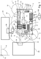
- the in Figure 1 The schematically shown in-vitro diagnostic laboratory arrangement according to the invention comprises, for example, two analysis devices 2A and 2B and a handling robot 1. In other embodiments, three or more analysis devices can also be provided.
- the handling robot 1 comprises a table 4 and two robot gripper arms 6 and 9 arranged on the table 4. Additional gripper arms can also be arranged on the table 4.
- the table 4 has a flat storage surface 5, the height at which the storage surface 5 of the table 4 is arranged corresponding to the usual working height of laboratory tables and is preferably between 80 and 110 cm.
- the storage surface 5 can alternatively also be divided into two or more spaced-apart partial surfaces.
- the horizontal The extent of the table 4 and the number of gripper arms may vary depending on the number of associated analyzers.
- the analysis devices 2A and 2B and the handling robot 1 are arranged in a fixed position and at a distance from one another in such a way that a walkable lane 8 remains between the table 4 of the handling robot 1 and the analysis devices 2A and 2B.
- This lane 8 enables an operator 12A to access the analysis devices 2A and 2B.
- the analysis devices 2A and 2B are, for example, devices for analyses in the field of immunology and clinical chemistry, devices for hematology diagnostics and/or devices for coagulation analysis, which are provided by different manufacturers.
- a first gripping arm 6 has a first access area 33 due to its positioning, its swivel range and the length of its links such that it can reach across the lane 8 to transfer sample containers to the analysis devices 2A and 2B or to receive them from the analysis devices 2A and 2B.
- the shelves 3A and 3B of the analysis devices 2A and 2B for receiving and transferring the sample containers are thus located in the first access area 33.
- several first gripping arms 6 can also be provided, which can be assigned to the same or different analysis devices. The access areas of the several first gripping arms 6 then together form the first access area 33.
- the storage area 5 of the table 4 is used for storing containers, in particular tubes containing samples or reagents. These containers are usually located in different holding devices, which are referred to as sample carriers, trays or racks. For example, several (for example 5 or 10) of the analysis devices 2A or 2B Sample containers to be supplied are placed in trays or racks, each with a corresponding number (for example 5 or 10) of receptacles. There are also analysis devices to which the sample containers are supplied in several racks, whereby the several racks are in turn placed in a so-called rack tray and supplied together.
- the storage area 5 of the table 4 comprises a buffer area 24 for storing the sample carriers 25 and 26 (e.g.
- the buffer area 24 is located in the access area 33 of the first gripping arm 6 (or the first gripping arms 6).
- the first gripping arm 6 can pick up the sample carriers 25 or 26 there and feed them to a storage area 3A or 3B of one of the analysis devices 2A or 2B.
- a second gripper arm 9 arranged approximately centrally on the table 4 has a second access area 34 which essentially covers the entire storage area 5 of the table 4.
- the handling robot 1 can also have several second gripper arms, wherein their access areas together form the second access area 34 and cover the entire surface of the table 4 and can also extend beyond the lane 8, so that the second gripper arms or some of the second gripper arms also have access to some of the analysis devices.
- the second access area 34 overlaps the first access area 33 in an overlap area 35.
- the buffer area 24 is arranged in this overlap area 35, so that both the first gripping arm 6 and the second gripping arm 9 have access to the buffer area 24 and thus a transfer of sample containers or sample carriers between the two gripping arms is made possible by a sample container deposited there by a first gripping arm or a sample carrier deposited there by a second gripper arm or vice versa. Since the overlap area 35 allows multiple gripper arms to access sample containers placed there, it is possible for the control device to flexibly decide which gripper arm will carry out transport tasks to be planned above the table depending on the utilization of the gripper arms. This flexibility in turn enables a higher overall throughput.
- the storage surface 5 of the table 4 comprises a sample inlet area 10 in which sample containers and in particular receiving devices 11 containing sample containers (i.e. sample carriers, trays or racks) are deposited, which contain samples to be analyzed. These newly incoming containers or sample carriers 11 with samples to be analyzed can, for example, be deposited manually by an operator 12B in the sample inlet area 10.
- the sample inlet area 10 is preferably located on an outer edge of the storage surface 5 of the table 4 on a side facing away from the analysis devices 2A and 2B.
- the incoming sample containers are transported to the sample inlet area 10 by a conveyor device (for example a chute, a conveyor belt or a robot arm), so that the operator 12B does not need to approach the table 4.
- the sample carriers 11 to be placed in the sample inlet area 10 can accommodate a predetermined number of sample containers and have, for example, 25 receptacles arranged in a matrix of five rows and five columns.
- Figure 1 In the schematically illustrated embodiment, the sample inlet area 10 comprises a partial area for receiving sample carriers 11A for emergency samples, which are to be analyzed preferentially.
- the sample inlet area 10 could also additionally contain a device (a so-called bulk material sorter) which removes sample containers from a container containing a large number of unsorted sample containers, records their identification information and sorts the sample containers into receiving devices (sample carriers).
- a device a so-called bulk material sorter
- the sample inlet area 10 is located in the second access area 34 of the second gripper arm 9.
- the second gripper arm 9 is therefore primarily used for handling incoming sample containers, in particular for removing the sample containers from the sample carriers 11, 11A of the sample inlet area 10, for identifying the incoming sample containers and for inserting the sample containers into the sample carriers 25 or 26 for loading the analysis devices 2A and 2B, which are located in the buffer area 24.
- the identification of the incoming sample containers includes, for example, scanning a barcode applied to the surface of the sample containers or another identification (e.g. a QR code).
- the second gripper 9 grasps a sample container to be identified and brings it into the scanning area of a scanning station 7. The identification recorded by the scanning station 7 is then checked.
- the information thus obtained from the barcode (or other code), the fill level detection and/or the detection of the external features of the container is compared, for example, with information stored in a database.
- the storage area 5 comprises an error area 36 with a receiving device 36A for containers containing samples for which there is (as yet) no order, as well as receiving devices 36B for faulty samples, for example insufficiently filled containers or containers whose external appearance (e.g. the cap color) does not match the sample information derived from the identification information.
- Figure 2 shows a schematic side view of the Figure 1 illustrated handling robot 1 with the table 4 and the two gripping arms 6 and 9 as well as some devices arranged on and in the table 4.
- the handling robot 1 comprises further devices on or in the table 4 which serve for pre-treatment (pre-analysis) of incoming samples before feeding them to an analysis device 2A, 2B.
- These devices comprise a three-jaw holder 39 (or another holding device) for holding a sample container for the purpose of removing its cap, which uncapping can be carried out with the aid of a gripping tool of the gripping arm 9. This tool grips the cap and rotates so that the cap is unscrewed or pulled off.
- a pipetting station 32 is provided on the table 4, at which, with the aid of pipettes that can be operated by a gripping tool of the gripping arm 9, parts of a sample can be taken from a sample container and filled into another sample container provided there.
- a gripper arm 9 In order for a gripper arm 9 to be able to carry out the different functions, various gripping tools are provided at a gripper changing station 29. Gripping tools are provided here for the different functions, such as gripping the sample containers, removing a cap or pipetting.
- the gripper changing station allows the different gripping tools to be changed automatically.
- the gripper changing station 29 is preferably arranged in the overlapping area 35 of the two access areas 33 and 34, so that it is accessible for both gripper arms 6 and 9.
- the devices used for pre-analytics also include a centrifuge 40, which is arranged in the table 4 under the storage surface 5 and is indicated by a dashed line in Figure 2 is shown schematically.
- a receptacle 38 of the under-table centrifuge 40 is shown schematically, into which a centrifuge cup, ie a receptacle for sample containers to be centrifuged, can be inserted.
- the storage area 5 of the table 4 also includes an area in which receiving devices 20 (sample carriers) for control samples can be placed.
- This area also includes a cooling device 21, which allows the control samples to be stored cooled in a predetermined temperature range. This allows the handling robot 1 to supply control samples to the analysis devices 2A and 2B at predetermined intervals and to keep these control samples for a longer period of time, so that no fresh control samples need to be supplied to the sample inlet area 10 during this period, ie no operator intervention is required.
- the storage area 5 further comprises an archive area 27 in which receiving devices for sample containers are arranged.
- the archive area 27 comprises a cooled area with a cooling device 23 and an uncooled area.
- the receiving devices 22 in the cooled area can be used to receive sample containers with test material samples that are to be issued to an external laboratory arrangement, i.e. for which the desired analysis cannot be carried out with the existing analysis devices 2A and 2B.
- sample containers for which the required analyses have already been carried out can be stored in the receiving devices 28 of the archive area 27.
- a handling of sample containers can also be carried out, which follows the analysis carried out (so-called post-analysis).
- a control device 13 is arranged, for example, under the table 4 of the handling robot 1, as shown in Figure 1 and Figure 2 is shown by a dashed line.
- the control device 13 comprises one or more computers and is coupled via adapted interfaces with devices (not shown in the figures) for controlling the two gripping arms as well as with the identification device 7 and the devices (also not shown) for level detection and for detecting the external characteristics of a sample tube (e.g. cap color).
- the control device 13 is connected to the control devices of the analysis devices as well as with at least one operator terminal, which comprises a display device (e.g. a screen or touchscreen) and conventional input devices (keyboard, mouse, voice input device, etc.).
- the control device 13, which comprises one or more computer systems, is also integrated into a data communication network, via which it can be coupled to other data processing systems in the laboratory.
- the control device 13 is coupled to further devices arranged on and under the table, such as the centrifuge and the pipetting station, and a series of sensor devices (not shown in the drawing) which are assigned to the various areas of the storage surface 5, such as the sample input area 10, the buffer area 24, the archive area 27, the receiving devices 20 for control samples and the error area 36, and which can detect the presence of the receiving devices and/or their occupancy with sample containers and other containers (e.g. for chemicals).
- a series of sensor devices (not shown in the drawing) which are assigned to the various areas of the storage surface 5, such as the sample input area 10, the buffer area 24, the archive area 27, the receiving devices 20 for control samples and the error area 36, and which can detect the presence of the receiving devices and/or their occupancy with sample containers and other containers (e.g. for chemicals).
- the control device 13 is also coupled to a sensor arrangement which includes, among other things, sensors 14 and 15 arranged on the table 4 and the sensor 16. With the help of these sensors 14, 15 and 16, the space surrounding the handling robot 1, in particular the lane 8 between the table 4 and the analysis devices 2A, 2B, is monitored.
- the sensors 14 and 15 are arranged on the rectangular table 4 near the floor on the diagonally opposite corner edges.
- the detection range of the sensor 14 is schematically shown by the angle shown by the dashed line 17 and the detection range of the sensor 15 by the angle shown by the dashed line 18.
- the passage between the two devices resulting from the distance between the analysis devices 2A and 2B is measured by the additional sensor 16 with the detection angle 19.
- the sensors 14, 15 and 16 detect both the intrusion of a person 12A or 12B or another object into the access areas 33 and 34 of the gripping arms 6 and 9 and the approach of the person or object to these access areas 33, 34.
- the signals indicating the approach of persons or objects to the access areas or the intrusion of persons or objects into the access areas are transmitted by the sensors and the sensor signal processing devices, if present, to the control device 13.
- the associated gripper arm 6 or 9 is prompted by the control device 13 to slow down its gripping movements and pivoting movements.
- both gripper arms 6 and 9 are prompted to slow down their gripping movements and pivoting movements.
- the affected gripper arm is prompted by the control device 13 to stop its movement completely. The movement is stopped until all people or objects have left the associated access area. The slowing down of the movement is stopped as soon as there are no more people or objects in the vicinity of the access areas, i.e. the distance to the access areas falls below the predetermined distance.
- the sensors 14, 15 and 16 and the control device 13 are configured such that the control device 13 further determines, based on the signals from the sensors 14, 15 and 16, in which direction and at what speed the detected persons or objects are moving, so that a reduced speed of movement or the cessation of any movement can be carried out in advance depending on the movements of the objects.
Landscapes
- Engineering & Computer Science (AREA)
- Robotics (AREA)
- Mechanical Engineering (AREA)
- Physics & Mathematics (AREA)
- Health & Medical Sciences (AREA)
- Life Sciences & Earth Sciences (AREA)
- Chemical & Material Sciences (AREA)
- Analytical Chemistry (AREA)
- Biochemistry (AREA)
- General Health & Medical Sciences (AREA)
- General Physics & Mathematics (AREA)
- Immunology (AREA)
- Pathology (AREA)
- Automatic Analysis And Handling Materials Therefor (AREA)
Priority Applications (2)
| Application Number | Priority Date | Filing Date | Title |
|---|---|---|---|
| EP23178093.3A EP4474826A1 (fr) | 2023-06-07 | 2023-06-07 | Ensemble de laboratoire de diagnostic in vitro comprenant des analyseurs et un robot manipulateur comportant au moins deux bras de préhension et une table dotée d'une surface de rangement |
| PCT/EP2024/065402 WO2024251773A1 (fr) | 2023-06-07 | 2024-06-05 | Installation de laboratoire de diagnostic in vitro comprenant des dispositifs d'analyse et un robot de manipulation avec au moins deux bras de préhension et une table avec une surface de support |
Applications Claiming Priority (1)
| Application Number | Priority Date | Filing Date | Title |
|---|---|---|---|
| EP23178093.3A EP4474826A1 (fr) | 2023-06-07 | 2023-06-07 | Ensemble de laboratoire de diagnostic in vitro comprenant des analyseurs et un robot manipulateur comportant au moins deux bras de préhension et une table dotée d'une surface de rangement |
Publications (1)
| Publication Number | Publication Date |
|---|---|
| EP4474826A1 true EP4474826A1 (fr) | 2024-12-11 |
Family
ID=86732638
Family Applications (1)
| Application Number | Title | Priority Date | Filing Date |
|---|---|---|---|
| EP23178093.3A Pending EP4474826A1 (fr) | 2023-06-07 | 2023-06-07 | Ensemble de laboratoire de diagnostic in vitro comprenant des analyseurs et un robot manipulateur comportant au moins deux bras de préhension et une table dotée d'une surface de rangement |
Country Status (2)
| Country | Link |
|---|---|
| EP (1) | EP4474826A1 (fr) |
| WO (1) | WO2024251773A1 (fr) |
Families Citing this family (2)
| Publication number | Priority date | Publication date | Assignee | Title |
|---|---|---|---|---|
| DE102024116179A1 (de) * | 2024-06-10 | 2025-12-11 | Analytik Jena Gmbh+Co. Kg | Verfahren zur Beschickung eines Probengeräts |
| DE102024116178A1 (de) * | 2024-06-10 | 2025-12-11 | Analytik Jena Gmbh+Co. Kg | Lagermodul für ein Probengerät |
Citations (3)
| Publication number | Priority date | Publication date | Assignee | Title |
|---|---|---|---|---|
| US20210094184A1 (en) * | 2019-09-27 | 2021-04-01 | HighRes Biosolutions, Inc. | Robotic transport system and method therefor |
| DE102021114970A1 (de) | 2021-06-10 | 2021-10-14 | Diabots GmbH | Medizintechnische Vorrichtung zur automatischen Probenanalyse |
| DE202022103719U1 (de) * | 2021-08-24 | 2022-10-12 | Siemens Healthcare Gmbh | Autonomer mobiler Laborassistenzroboter für ein in vitro diagnostisches Labor |
-
2023
- 2023-06-07 EP EP23178093.3A patent/EP4474826A1/fr active Pending
-
2024
- 2024-06-05 WO PCT/EP2024/065402 patent/WO2024251773A1/fr not_active Ceased
Patent Citations (3)
| Publication number | Priority date | Publication date | Assignee | Title |
|---|---|---|---|---|
| US20210094184A1 (en) * | 2019-09-27 | 2021-04-01 | HighRes Biosolutions, Inc. | Robotic transport system and method therefor |
| DE102021114970A1 (de) | 2021-06-10 | 2021-10-14 | Diabots GmbH | Medizintechnische Vorrichtung zur automatischen Probenanalyse |
| DE202022103719U1 (de) * | 2021-08-24 | 2022-10-12 | Siemens Healthcare Gmbh | Autonomer mobiler Laborassistenzroboter für ein in vitro diagnostisches Labor |
Also Published As
| Publication number | Publication date |
|---|---|
| WO2024251773A1 (fr) | 2024-12-12 |
Similar Documents
| Publication | Publication Date | Title |
|---|---|---|
| EP2730927B1 (fr) | Poste de réactif pour un appareil d'analyse automatique | |
| DE69429840T2 (de) | Transportsystem für ein Analysengerät für Flüssigkeiten | |
| DE112010000822B4 (de) | Automatische Analysevorrichtung und automatisches Analyseverfahren | |
| DE69806990T2 (de) | Moduläres Probenanalysesytem | |
| EP0937983B1 (fr) | Analyseur automatique | |
| DE3883079T2 (de) | Probenkreis für klinisches Analysatorennetz. | |
| DE69835795T2 (de) | Vorrichtung zur automatischen Durchführung von Laboratoriumprüfungen | |
| EP1496365B1 (fr) | Dispositif et procédé de transport d'objets | |
| DE60207499T2 (de) | Übertrageeinheit sowie diese beinhaltende automatische Analysevorrichtung | |
| EP1662261B1 (fr) | Dispositif d'analyse d'échantillons | |
| WO2024251773A1 (fr) | Installation de laboratoire de diagnostic in vitro comprenant des dispositifs d'analyse et un robot de manipulation avec au moins deux bras de préhension et une table avec une surface de support | |
| DE60201269T2 (de) | Verfahren und system zur automatischen immunchemischen analyse | |
| EP2027926B1 (fr) | Appareil de fonctionnement de matériel biologique | |
| DE69834983T2 (de) | Automatisches Blutanalysesystem | |
| EP2927163A1 (fr) | Dispositif de transport vertical, système de distribution d'échantillons et système d'automatisation de laboratoire | |
| EP2998744B1 (fr) | Dispositif d'incubation pour un appareil d'analyse automatique | |
| WO1993020612A2 (fr) | Dispositif automatique pour l'analyse photometrique d'echantillons liquides | |
| DE102021114970A1 (de) | Medizintechnische Vorrichtung zur automatischen Probenanalyse | |
| EP3216517B1 (fr) | Procede de melange d'un liquide dans un appareil d'analyse automatique | |
| EP0651254A1 (fr) | Nécessaire à réactifs et analyseur l'utilisant | |
| EP3436832B1 (fr) | Dispositif de transport | |
| EP1443100A1 (fr) | Armoire de climatisation ainsi que dispositif et méthode de sa surveillance | |
| EP2492015A1 (fr) | Porte-échantillon, système et procédé d'analyse | |
| DE3851998T2 (de) | Geräte für biochemische Analyse. | |
| EP3550308A1 (fr) | Système d'analyse de laboratoire à pipetage d'échantillon amélioré |
Legal Events
| Date | Code | Title | Description |
|---|---|---|---|
| PUAI | Public reference made under article 153(3) epc to a published international application that has entered the european phase |
Free format text: ORIGINAL CODE: 0009012 |
|
| STAA | Information on the status of an ep patent application or granted ep patent |
Free format text: STATUS: THE APPLICATION HAS BEEN PUBLISHED |
|
| AK | Designated contracting states |
Kind code of ref document: A1 Designated state(s): AL AT BE BG CH CY CZ DE DK EE ES FI FR GB GR HR HU IE IS IT LI LT LU LV MC ME MK MT NL NO PL PT RO RS SE SI SK SM TR |
|
| STAA | Information on the status of an ep patent application or granted ep patent |
Free format text: STATUS: REQUEST FOR EXAMINATION WAS MADE |
|
| 17P | Request for examination filed |
Effective date: 20241212 |