EP4475228A1 - Batterie secondaire entièrement solide - Google Patents
Batterie secondaire entièrement solide Download PDFInfo
- Publication number
- EP4475228A1 EP4475228A1 EP24180016.8A EP24180016A EP4475228A1 EP 4475228 A1 EP4475228 A1 EP 4475228A1 EP 24180016 A EP24180016 A EP 24180016A EP 4475228 A1 EP4475228 A1 EP 4475228A1
- Authority
- EP
- European Patent Office
- Prior art keywords
- layer
- active material
- composite
- cathode
- secondary battery
- Prior art date
- Legal status (The legal status is an assumption and is not a legal conclusion. Google has not performed a legal analysis and makes no representation as to the accuracy of the status listed.)
- Pending
Links
Images


Classifications
-
- H—ELECTRICITY
- H01—ELECTRIC ELEMENTS
- H01M—PROCESSES OR MEANS, e.g. BATTERIES, FOR THE DIRECT CONVERSION OF CHEMICAL ENERGY INTO ELECTRICAL ENERGY
- H01M10/00—Secondary cells; Manufacture thereof
- H01M10/05—Accumulators with non-aqueous electrolyte
- H01M10/052—Li-accumulators
-
- H—ELECTRICITY
- H01—ELECTRIC ELEMENTS
- H01M—PROCESSES OR MEANS, e.g. BATTERIES, FOR THE DIRECT CONVERSION OF CHEMICAL ENERGY INTO ELECTRICAL ENERGY
- H01M10/00—Secondary cells; Manufacture thereof
- H01M10/05—Accumulators with non-aqueous electrolyte
- H01M10/056—Accumulators with non-aqueous electrolyte characterised by the materials used as electrolytes, e.g. mixed inorganic/organic electrolytes
- H01M10/0561—Accumulators with non-aqueous electrolyte characterised by the materials used as electrolytes, e.g. mixed inorganic/organic electrolytes the electrolyte being constituted of inorganic materials only
- H01M10/0562—Solid materials
-
- H—ELECTRICITY
- H01—ELECTRIC ELEMENTS
- H01M—PROCESSES OR MEANS, e.g. BATTERIES, FOR THE DIRECT CONVERSION OF CHEMICAL ENERGY INTO ELECTRICAL ENERGY
- H01M10/00—Secondary cells; Manufacture thereof
- H01M10/05—Accumulators with non-aqueous electrolyte
- H01M10/056—Accumulators with non-aqueous electrolyte characterised by the materials used as electrolytes, e.g. mixed inorganic/organic electrolytes
- H01M10/0564—Accumulators with non-aqueous electrolyte characterised by the materials used as electrolytes, e.g. mixed inorganic/organic electrolytes the electrolyte being constituted of organic materials only
- H01M10/0565—Polymeric materials, e.g. gel-type or solid-type
-
- H—ELECTRICITY
- H01—ELECTRIC ELEMENTS
- H01M—PROCESSES OR MEANS, e.g. BATTERIES, FOR THE DIRECT CONVERSION OF CHEMICAL ENERGY INTO ELECTRICAL ENERGY
- H01M4/00—Electrodes
- H01M4/02—Electrodes composed of, or comprising, active material
- H01M4/13—Electrodes for accumulators with non-aqueous electrolyte, e.g. for lithium-accumulators; Processes of manufacture thereof
- H01M4/136—Electrodes based on inorganic compounds other than oxides or hydroxides, e.g. sulfides, selenides, tellurides, halogenides or LiCoFy
-
- H—ELECTRICITY
- H01—ELECTRIC ELEMENTS
- H01M—PROCESSES OR MEANS, e.g. BATTERIES, FOR THE DIRECT CONVERSION OF CHEMICAL ENERGY INTO ELECTRICAL ENERGY
- H01M4/00—Electrodes
- H01M4/02—Electrodes composed of, or comprising, active material
- H01M4/36—Selection of substances as active materials, active masses, active liquids
- H01M4/362—Composites
- H01M4/366—Composites as layered products
-
- H—ELECTRICITY
- H01—ELECTRIC ELEMENTS
- H01M—PROCESSES OR MEANS, e.g. BATTERIES, FOR THE DIRECT CONVERSION OF CHEMICAL ENERGY INTO ELECTRICAL ENERGY
- H01M4/00—Electrodes
- H01M4/02—Electrodes composed of, or comprising, active material
- H01M4/36—Selection of substances as active materials, active masses, active liquids
- H01M4/38—Selection of substances as active materials, active masses, active liquids of elements or alloys
- H01M4/40—Alloys based on alkali metals
- H01M4/405—Alloys based on lithium
-
- H—ELECTRICITY
- H01—ELECTRIC ELEMENTS
- H01M—PROCESSES OR MEANS, e.g. BATTERIES, FOR THE DIRECT CONVERSION OF CHEMICAL ENERGY INTO ELECTRICAL ENERGY
- H01M4/00—Electrodes
- H01M4/02—Electrodes composed of, or comprising, active material
- H01M4/36—Selection of substances as active materials, active masses, active liquids
- H01M4/58—Selection of substances as active materials, active masses, active liquids of inorganic compounds other than oxides or hydroxides, e.g. sulfides, selenides, tellurides, halogenides or LiCoFy; of polyanionic structures, e.g. phosphates, silicates or borates
- H01M4/581—Chalcogenides or intercalation compounds thereof
- H01M4/5815—Sulfides
-
- H—ELECTRICITY
- H01—ELECTRIC ELEMENTS
- H01M—PROCESSES OR MEANS, e.g. BATTERIES, FOR THE DIRECT CONVERSION OF CHEMICAL ENERGY INTO ELECTRICAL ENERGY
- H01M4/00—Electrodes
- H01M4/02—Electrodes composed of, or comprising, active material
- H01M4/62—Selection of inactive substances as ingredients for active masses, e.g. binders, fillers
- H01M4/621—Binders
-
- H—ELECTRICITY
- H01—ELECTRIC ELEMENTS
- H01M—PROCESSES OR MEANS, e.g. BATTERIES, FOR THE DIRECT CONVERSION OF CHEMICAL ENERGY INTO ELECTRICAL ENERGY
- H01M4/00—Electrodes
- H01M4/02—Electrodes composed of, or comprising, active material
- H01M4/62—Selection of inactive substances as ingredients for active masses, e.g. binders, fillers
- H01M4/624—Electric conductive fillers
- H01M4/625—Carbon or graphite
-
- H—ELECTRICITY
- H01—ELECTRIC ELEMENTS
- H01M—PROCESSES OR MEANS, e.g. BATTERIES, FOR THE DIRECT CONVERSION OF CHEMICAL ENERGY INTO ELECTRICAL ENERGY
- H01M50/00—Constructional details or processes of manufacture of the non-active parts of electrochemical cells other than fuel cells, e.g. hybrid cells
- H01M50/10—Primary casings; Jackets or wrappings
- H01M50/14—Primary casings; Jackets or wrappings for protecting against damage caused by external factors
- H01M50/143—Fireproof; Explosion-proof
-
- H—ELECTRICITY
- H01—ELECTRIC ELEMENTS
- H01M—PROCESSES OR MEANS, e.g. BATTERIES, FOR THE DIRECT CONVERSION OF CHEMICAL ENERGY INTO ELECTRICAL ENERGY
- H01M4/00—Electrodes
- H01M4/02—Electrodes composed of, or comprising, active material
- H01M2004/021—Physical characteristics, e.g. porosity, surface area
-
- H—ELECTRICITY
- H01—ELECTRIC ELEMENTS
- H01M—PROCESSES OR MEANS, e.g. BATTERIES, FOR THE DIRECT CONVERSION OF CHEMICAL ENERGY INTO ELECTRICAL ENERGY
- H01M4/00—Electrodes
- H01M4/02—Electrodes composed of, or comprising, active material
- H01M2004/026—Electrodes composed of, or comprising, active material characterised by the polarity
- H01M2004/027—Negative electrodes
-
- H—ELECTRICITY
- H01—ELECTRIC ELEMENTS
- H01M—PROCESSES OR MEANS, e.g. BATTERIES, FOR THE DIRECT CONVERSION OF CHEMICAL ENERGY INTO ELECTRICAL ENERGY
- H01M4/00—Electrodes
- H01M4/02—Electrodes composed of, or comprising, active material
- H01M2004/026—Electrodes composed of, or comprising, active material characterised by the polarity
- H01M2004/028—Positive electrodes
-
- H—ELECTRICITY
- H01—ELECTRIC ELEMENTS
- H01M—PROCESSES OR MEANS, e.g. BATTERIES, FOR THE DIRECT CONVERSION OF CHEMICAL ENERGY INTO ELECTRICAL ENERGY
- H01M2300/00—Electrolytes
- H01M2300/0017—Non-aqueous electrolytes
- H01M2300/0065—Solid electrolytes
- H01M2300/0082—Organic polymers
-
- Y—GENERAL TAGGING OF NEW TECHNOLOGICAL DEVELOPMENTS; GENERAL TAGGING OF CROSS-SECTIONAL TECHNOLOGIES SPANNING OVER SEVERAL SECTIONS OF THE IPC; TECHNICAL SUBJECTS COVERED BY FORMER USPC CROSS-REFERENCE ART COLLECTIONS [XRACs] AND DIGESTS
- Y02—TECHNOLOGIES OR APPLICATIONS FOR MITIGATION OR ADAPTATION AGAINST CLIMATE CHANGE
- Y02E—REDUCTION OF GREENHOUSE GAS [GHG] EMISSIONS, RELATED TO ENERGY GENERATION, TRANSMISSION OR DISTRIBUTION
- Y02E60/00—Enabling technologies; Technologies with a potential or indirect contribution to GHG emissions mitigation
- Y02E60/10—Energy storage using batteries
Definitions
- One or more embodiments relate to an all-solid secondary battery.
- a lithium secondary battery is a battery including an electrolyte, and a cathode and an anode, each including an active material capable of intercalating and deintercalating lithium ions.
- Lithium secondary batteries produce electrical energy through oxidation and reduction reactions if lithium ions are intercalated/deintercalated into/from a cathode and anode.
- lithium batteries are being commercialized not only in the fields of information-related devices and communication devices but also in the field of vehicles.
- the vehicles are related to life, and thus safety is especially important.
- Lithium batteries use an electrolyte including a flammable organic solvent as an electrolyte, and thus short circuit occurs, resulting in a possibility of overheating and fire.
- All-solid batteries do not use a flammable organic solvent, and thus even if a short circuit occurs, a possibility of fire or explosion may be considerably reduced. In such all-solid batteries, safety may be considerably increased as compared with lithium batteries using an electrolyte.
- a secondary battery uses a sulfur-based material (for example, S) as a cathode active material to increase capacity.
- S sulfur-based material
- polysulfide is generated from a sulfur-based material, and the generated polysulfide moves to an anode and reacts with the anode. Due to such a side reaction, the lifespan characteristics of a secondary battery are degraded.
- a secondary battery capable of suppressing a side reaction between polysulfide and a lithium metal.
- a volume of the sulfur-based material may be increased during initial discharging so that the volume may be decreased again during a charging process, and a transfer path of ions and/or electrons in an electrode may be disconnected in a process in which the volume of the sulfur-based material is increased.
- a transfer path of ions and/or electrons causes deterioration of a secondary battery.
- Defects occur in a solid electrolyte layer during a manufacturing process and/or a charging/discharging process of a secondary battery, and due to such defects, cracks occur and grow in the solid electrolyte layer. As lithium grows through such cracks, a short circuit occurs. There is a need for a secondary battery capable of suppressing the occurrence of such defects during a manufacturing process and/or a charging/discharging process of a secondary battery.
- One or more embodiments include a secondary battery with a new structure which prevents a side reaction between an electrolyte layer and a lithium metal during charging/discharging, suppresses the discontinuation of a transfer path of ions and/or electrons, prevents a side reaction caused by polysulfide during charging/discharging, and suppresses defects in a secondary battery during manufacturing and/or charging/discharging.
- an all-solid secondary battery includes a cathode layer, an anode layer, a solid electrolyte layer disposed between the cathode layer and the anode layer, and a first inactive member disposed on one side of the cathode layer
- the cathode layer includes a cathode current collector and a cathode active material layer disposed on one side or two sides of the cathode current collector
- the cathode active material layer includes a lithium-containing sulfide-based cathode active material
- the lithium-containing sulfide-based cathode active material includes Li 2 S, a Li 2 S-containing composite, or a combination thereof
- the anode layer includes an anode current collector and a first anode active material layer disposed on one side of the anode current collector, a ratio (B/A) of an initial charge capacity (B) of the first anode active material layer to an initial charge capacity (A) of the catho
- an all-solid secondary battery includes a cathode layer, an anode layer, and a solid electrolyte layer disposed between the cathode layer and the anode layer, wherein the cathode layer includes a cathode current collector and a cathode active material layer disposed on one side or two sides of the cathode current collector, and the anode layer includes an anode current collector and a first anode active material layer disposed on one side of the anode current collector, wherein the cathode active material layer includes a lithium-containing sulfide-based cathode active material, the lithium-containing sulfide-based cathode active material includes a Li 2 S-containing composite, and the Li 2 S-containing composite includes a composite of Li 2 S and a lithium salt, a composite of Li 2 S, a lithium salt, and a conductive material, a composite of Li 2 S and a metal halide, a composite of Li 2 S
- An all-solid secondary battery includes a cathode layer, an anode layer, a solid electrolyte layer disposed between the cathode layer and the anode layer, and a first inactive member disposed on one side of the cathode layer, wherein the cathode layer includes a cathode current collector and a cathode active material layer disposed on one side or two sides of the cathode current collector, the cathode active material layer includes a lithium-containing sulfide-based cathode active material, the lithium-containing sulfide-based cathode active material includes a Li 2 S-containing composite, and the anode layer includes an anode current collector and a first anode active material layer disposed on one side of the anode current collector.
- an element is "on” another element, it will be understood that the element may be disposed directly on another element or still another element may be interposed therebetween. In other embodiments, if it is described that an element is "directly on” another element, still another element is not interposed therebetween.
- first,” “second,” and “third” may be used herein to describe various elements, components, regions, layers, and/or sections, these elements, components, regions, layers, and/or sections should not be limited by these terms. These terms are only used to distinguish one element, component, region, layer, or section from another region, layer, or section. Thus, a first element, component, region, layer, or section described below may be termed a second element, component, region, layer, or section without departing from the teachings of the present specification.
- spatially relative terms such as “beneath,” “below,” “lower,” “above,” and “upper” may be used herein to easily describe one element or feature's relationship to another element or feature. It will be understood that the spatially relative terms are intended to encompass different orientations of a device in use or operation in addition to the orientation illustrated in the drawings. For example, if a device in the drawings is turned over, elements described as “below” or “beneath” other elements or features would then be “above” or “over” the other elements or features. Thus, the example term “below” may encompass both orientations of above and below. The device may be otherwise oriented (rotated 90 degrees or at other orientations), and the spatially relative terms used herein may be interpreted accordingly.
- Embodiments are described herein with reference to cross-sectional views which are schematic diagrams of embodiments. As such, variations from the shapes of the illustrations as a result, for example, of manufacturing techniques and/or tolerances, are to be expected. Thus, the embodiments described herein should not be construed as limited to the particular shapes regions of illustrated herein but may include deviations in shapes that result, for example, from manufacturing. For example, regions illustrated or described as being flat may be typically rough and/or have nonlinear features. Moreover, sharp-drawn angles may be round. Thus, regions illustrated in the drawings are schematic in nature and their shapes are not intended to illustrate the actual shape of a region and are not intended to limit the scope of the claims.
- Group refers to a Group of the periodic table of the elements according to the International Union of Pure and Applied Chemistry (“IUPAC”) Groups 1-18 group classification system.
- IUPAC International Union of Pure and Applied Chemistry
- a particle diameter may be an average particle diameter.
- a particle diameter refers to an average particle diameter (D50) which refers to a diameter of particles with a cumulative volume of 50 vol% in a particle size distribution.
- the average particle diameter (D50) may be measured through methods well known to those skilled in the art, for example, by using a particle size analyzer (PSA), a transmission electron microscope (TEM) image, or a scanning electron microscope (SEM) image. Through other methods, measurement may be performed by using a measuring device using dynamic light-scattering, data analysis is performed to count the number of particles for each particle size range, and then a value of the average particle diameter (D50) may be easily obtained therefrom through calculation.
- PSD particle size analyzer
- TEM transmission electron microscope
- SEM scanning electron microscope
- the average particle diameter (D50) may be measured by using a laser diffraction method.
- particles to be measured may be dispersed in a dispersion medium to then be introduced into a commercially available laser diffraction particle diameter measuring device (for example, Microtrac MT 3000), 28 kHz ultrasonic waves may be irradiated thereon at an output power of about 60 W, and then the average particle diameter (D50) based on 50% of a particle diameter distribution may calculated in the measuring device.
- a laser diffraction particle diameter measuring device for example, Microtrac MT 3000
- 28 kHz ultrasonic waves may be irradiated thereon at an output power of about 60 W
- the average particle diameter (D50) based on 50% of a particle diameter distribution may calculated in the measuring device.
- particle diameter refers to an average diameter if particles are spherical and refers to an average major axis length if particles are non-spherical.
- An “average particle diameter” refers to, for example, D50, which is a median particle diameter.
- D50 is a particle size corresponding to a 50% cumulative volume if a particle size distribution measured through a laser diffraction method is calculated from particles having a smaller particle size.
- D90 is a particle size corresponding to a 90% cumulative volume if a particle size distribution measured through a laser diffraction method is calculated from particles having a smaller particle size.
- D10 is a particle size corresponding to a 10% cumulative volume if a particle size distribution measured through a laser diffraction method is calculated from particles having a smaller particle size.
- metal as used herein includes all of metals and metalloids such as silicon and germanium in an elemental or ionic state.
- alloy refers to a mixture of two or more metals.
- electrode active material refers to an electrode material that may undergo lithiation and delithiation.
- cathode active material refers to a cathode material that may undergo lithiation and delithiation.
- anode active material refers to an anode material that may undergo lithiation and delithiation.
- lithiumate and “lithiating” as used herein refer to a process of adding lithium to an electrode active material.
- delivery and “delithiating” as used herein refer to a process of removing lithium from an electrode active material.
- charge and “charging” as used herein refer to a process of providing electrochemical energy to a battery.
- discharge and “discharging” as used herein refer to a process of removing electrochemical energy from a battery.
- positive electrode and “cathode” as used herein refer to an electrode at which electrochemical reduction and lithiation occur during a discharging process.
- negative electrode and “anode” as used herein refer to an electrode at which electrochemical oxidation and delithiation occur during a discharging process.
- An all-solid secondary battery may include a cathode layer, an anode layer, a solid electrolyte layer disposed between the cathode layer and the anode layer, and a first inactive member disposed on one side of the cathode layer.
- the cathode layer may include a cathode current collector and a cathode active material layer disposed on one side or two sides of the cathode current collector.
- the cathode active material layer may include a lithium-containing sulfide-based cathode active material.
- the lithium-containing sulfide-based cathode active material may include Li 2 S, a Li 2 S-containing composite, or a combination thereof.
- the anode layer may include an anode current collector and a first anode active material layer disposed on one side of the anode current collector.
- a ratio (B/A) of an initial charge capacity (B) of the first anode active material layer to initial charge capacity (A) of the cathode active material layer may be in a range of about 0.005 to about 0.45.
- the initial charge capacity of the cathode active material layer may be determined by charging from a 1 st open circuit voltage (OCV) up to a maximum charging voltage for Li/Li + (e.g., a maximum charging voltage vs. Li/Li + ).
- the initial charge capacity of the anode active material layer may be determined by charging from a 2 nd OCV up to a voltage of about 0.01 V for Li/Li + .
- the all-solid secondary battery may include the lithium-containing sulfide-based cathode active material as a lithium source instead of a lithium metal.
- a lithium source such as a lithium metal may be omitted from the anode layer. A volume of the anode layer may be reduced, thereby increasing an energy density of the all-solid secondary battery.
- the all-solid secondary battery may include the lithium-containing sulfide-based cathode active material as a cathode active material.
- the disconnection of a transfer path of ions and/or electrons due to an increase in volume of a lithium-free sulfide-based cathode active material, for example, sulfur (S), during initial discharging may be prevented.
- S sulfur
- the disconnection of the transfer path of ions and/or electrons may be prevented, thereby improving the cycle characteristics of the all-solid secondary battery.
- the all-solid secondary battery may include the first anode active material layer having the initial charge capacity in a range of about 0.005 to about 0.45 with respect to the initial charge capacity of the cathode active material layer.
- the first anode active material layer may have small initial charge capacity in such a range, and thus the anode layer may effectively compensate for a change in volume of the cathode layer during charging/discharging.
- a change in overall volume of the all-solid secondary battery may be suppressed during charging/discharging. Deterioration due to occurrence of cracks or the like caused by a rapid change in volume during charging/discharging of the all-solid secondary battery may be prevented, thereby preventing a short circuit of the all-solid secondary battery and improving cycle characteristics.
- the all-solid secondary battery may include the solid electrolyte layer, and thus polysulfide generated in the lithium-containing sulfide-based cathode active material during charging/discharging may be blocked from moving to the anode layer. In some embodiments, a side reaction between the polysulfide and the anode active material may be suppressed.
- a first inactive member may be disposed on one side of the cathode layer, thereby suppressing cracks of the solid electrolyte layer which occur during pressing and/or charging/discharging of the all-solid secondary battery.
- cracks of the solid electrolyte layer may be suppressed during manufacturing and/or charging/discharging of the all-solid secondary battery, thereby suppressing a short circuit of the all-solid secondary battery.
- a short circuit of the all-solid secondary battery may be prevented, and the lifespan characteristics thereof are improved.
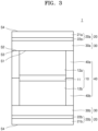
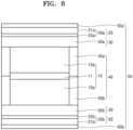
- an all-solid secondary battery 1 may include a cathode layer 10, an anode layer 20, and a solid electrolyte layer 30 disposed between the cathode layer 10 and the anode layer 20.
- the cathode layer 10 may include a cathode current collector 11 and a cathode active material layer 12 disposed on one side or two sides of the cathode current collector 11.
- the cathode active material layer 12 may include a sulfide-based cathode active material.
- the sulfide-based cathode active material may include Li 2 S, a Li 2 S-containing composite, or a combination thereof.
- the all-solid secondary battery 1 may include a first inactive member 40 disposed on one side of the cathode layer 10.
- the anode layer 20 may include an anode current collector 21 and a first anode active material layer 22 disposed on one side of the anode current collector 21.
- a ratio (B/A) of an initial charge capacity (B) of the first anode active material layer 22 to initial charge capacity (A) of the cathode active material layer 12 may be in a range of about 0.005 to about 0.45.
- the initial charge capacity of the cathode active material layer 12 may be determined by charging from a 1 st OCV up to a maximum charging voltage for Li/Li + .
- the initial charge capacity of the anode active material layer 22 may be determined by charging from a 2 nd OCV up to a voltage of about 0.01 V for Li/Li + .
- the ratio (B/A) of the initial charge capacity (B) of the first anode active material layer 22 to the initial charge capacity (A) of the cathode active material layer 12 may be, for example, in a range of about 0.01 to about 0.4, about 0.01 to about 0.3, or about 0.01 to about 0.1.
- the cathode active material layer 12 may include, for example, a cathode active material and a solid electrolyte.
- the solid electrolyte included in the cathode active material layer 12 may be similar to or different from a solid electrolyte included in the solid electrolyte layer 30.
- the solid electrolyte may be defined as in a section of the solid electrolyte layer 30.
- the cathode active material may include a lithium-containing sulfide-based cathode active material.
- the lithium-containing sulfide-based cathode material may be, for example, an electrode material in which lithium is added to a sulfur-based cathode active material.
- a sulfur-based cathode active material may include, for example, a sulfur-based material, a sulfur-based material-containing composite, or a combination thereof.
- the sulfur-based material may be, for example, inorganic sulfur, Li 2 S n , wherein n>1, a disulfide compound, an organic sulfur compound, a carbon-sulfur polymer, or a combination thereof.
- the sulfur-based material-containing composite may be a composite including inorganic sulfur, Li 2 S n , wherein n>1, a disulfide compound, an organic sulfur compound, a carbon-sulfur polymer, or a combination thereof.
- the sulfur-based material-containing composite may include, for example, a composite of a sulfur-based material and carbon, a composite of a sulfur-based material, carbon, and a solid electrolyte, a composite of a sulfur-based material, carbon, and a lithium salt, a composite of a sulfur-based material and a lithium salt, a composite of a sulfur-based material and a solid electrolyte, a composite of a sulfur-based material and a metal carbide, a composite of a sulfur-based material, carbon, and a metal carbide, a composite of a sulfur-based material and a metal nitride, a composite of a sulfur-based material, carbon, and a metal nitride, or a combination thereof.
- a lithium-containing sulfide-based cathode active material may provide a higher discharge capacity per unit weight than an oxide-based cathode active material, and thus an energy density per unit weight of an all-solid secondary battery including the lithium-containing sulfide-based cathode active material may be increased.
- the lithium-containing sulfide-based cathode active material may include, for example, Li 2 S, a Li 2 S-containing composite, or a combination thereof.
- the lithium-containing sulfide-based cathode active material may include Li 2 S, a Li 2 S-containing composite, or a combination thereof which has high capacity, and thus the use of a lithium metal may be omitted if an all-solid secondary battery is manufactured.
- a lithium metal may have high reactivity and high ductility, and thus the lithium metal may reduce mass productivity during manufacturing of a battery. In some embodiments, the mass productivity of an all-solid secondary battery may be improved.
- a lithium metal may be omitted from an anode layer, and thus a volume of the anode layer may be decreased, thereby improving an energy density per unit volume of an all-solid secondary battery and constituting an all-solid secondary battery having a simpler structure.
- the lithium-containing sulfide-based cathode active material may undergo delithiation, for example, during initial charging so that a volume thereof may be decreased, and the lithium-containing sulfide-based cathode active material may undergo lithiation again during subsequent discharging so that the volume thereof may be increased.
- the volume of the lithium-containing sulfide-based cathode active material may change in a state in which a transfer path of ions and/or electrons due to a conductive material or the like disposed around the lithium-containing sulfide-based cathode active material is maintained, and thus a possibility of the disconnection of the transfer path of ions and/or electrons may be low.
- the sulfur-based cathode active material (for example, S) may undergo lithiation, for example, during initial discharging so that a volume thereof may be increased, and the sulfur-based cathode active material may undergo delithiation again during subsequent charging so that the volume thereof may be decreased.
- an initial transfer path of ions and/or electrons due to a conductive material or the like disposed around the sulfur-based cathode active material may be collapsed due to an initial volume increase of the sulfur-based cathode active material, and thus a probability of the disconnection of the transfer path of ions and/or electrons may be high.
- a particle diameter (e.g. an average particle diameter, such as D50) of the lithium-containing sulfide-based cathode active material may be, for example, in a range of about 1 nm to about 50 ⁇ m, about 10 nm to about 50 ⁇ m, about 50 nm to about 40 ⁇ m, about 100 nm to about 30 ⁇ m, about 500 nm to about 30 ⁇ m, or about 1 ⁇ m to about 20 ⁇ m.
- the lithium-containing sulfide-based cathode active material may have a particle diameter within such a range, and thus the cycle characteristics of an all-solid secondary battery including the lithium sulfide-based cathode active material may be further improved.
- a Li 2 S-containing composite may be, for example, a composite of Li 2 S and a conductive material.
- the conductive material may be, for example, an ion-conductive material, an electron-conductive material, or a combination thereof.
- the electron-conductive material may have an electronic conductivity of, for example, 1.0 ⁇ 10 3 S/m, 1.0 ⁇ 10 4 S/m, or 1.0 ⁇ 10 5 S/m or more.
- the electron-conductive material may be, for example, in the form of a particulate electron-conductive material, a plate-like electron-conductive material, a rod-like electron-conductive material, or a combination thereof but is not necessarily limited thereto.
- the electron-conductive material may include, for example, carbon, a metal powder, a metal compound, or the like. If carbon is included as the electron-conductive material, carbon may have high electronic conductivity and may be light, and thus an all-solid secondary battery having a high energy density per unit mass may be implemented.
- the electron-conductive material may have pores.
- the electron-conductive material may have pores, and thus Li 2 S may be included in the pores, thereby increasing a contact area between Li 2 S and the electron-conductive material and increasing a specific surface area of Li 2 S.
- a pore volume may be in a range of, for example, about 0.1 cc/g to about 20.0 cc/g, about 0.5 cc/g to about 10 cc/g, or about 0.5 cc/g to about 5 cc/g.
- An average pore diameter may be in a range of, for example, about 1 nm to about 100 nm, about 1 nm to about 50 nm, or about 1 nm to about 20 nm.
- a Brunauer, Emmett, and Teller (BET) specific surface area of the electron-conductive material having pores may be in a range of about 200 m 2 /g to about 4,500 m 2 /g if the average pore diameter is 15 nm or less and may be in a range of about 100 m 2 /g to about 2,500 m 2 /g if the average pore diameter is greater than about 15 nm.
- a BET specific surface area, a pore diameter, a pore volume, and an average pore diameter may be obtained using, for example, a nitrogen adsorption method such as ASTM D6556, ASTM D4567, and/or ISO 9277:2022.
- the ion-conductive material may have an ionic conductivity of, for example, 1.0 ⁇ 10 -5 S/m, 1.0 ⁇ 10 -4 S/m, or 1.0 ⁇ 10 -3 S/m or more.
- the ion-conductive material may have pores.
- the ion-conductive material may have pores, and thus Li 2 S may be included in the pores, thereby increasing a contact area between Li 2 S and the ion-conductive material and increasing a specific surface area of Li 2 S.
- the ion-conductive material may be, for example, in the form of a particulate ion-conductive material, a plate-like ion-conductive material, a rod-like ion-conductive material, or a combination thereof but is not necessarily limited thereto.
- the ion-conductive material may be, for example, a sulfide-based solid electrolyte or an oxide-based solid electrolyte. If the sulfide-based solid electrolyte is included as the ion-conductive material, the sulfide-based solid electrolyte may have high ionic conductivity and may be shaped into various forms, thereby implementing an all-solid secondary battery having large capacity.
- the Li 2 S-containing composite may include, for example, a composite of Li 2 S and a conductive material, a composite of Li 2 S, a solid electrolyte, and a conductive material, a composite of Li 2 S and a solid electrolyte, a composite of Li 2 S, a lithium salt, and a conductive material, a composite of Li 2 S and a lithium salt, a composite of Li 2 S and a metal carbide, a composite of Li 2 S, a metal carbide, and a conductive material, a composite of Li 2 S and a metal nitride, a composite of Li 2 S, a metal nitride, and a conductive material, or a combination thereof.
- the Li 2 S-containing composite may be distinguished from a simple mixture of Li 2 S, a conductive material, a solid electrolyte, a lithium salt, a metal carbide, and a metal nitride.
- the simple mixture of Li 2 S, the conductive material, the solid electrolyte, the lithium salt, the metal carbide, and the metal nitride may provide high interfacial resistance because a dense interface between Li 2 S and these other components may not be maintained, and thus the lifespan characteristics of an all-solid secondary battery may deteriorate.
- the Li 2 S-containing composite may include, for example, a composite of Li 2 S and a lithium salt, a composite of Li 2 S, a lithium salt, and a conductive material, a composite of Li 2 S and a metal halide, a composite of Li 2 S, a metal halide, and a conductive material, a composite of Li 2 S, a lithium salt, and a metal halide, a composite of Li 2 S, a lithium salt, a metal halide, and a conductive material, or a combination thereof.
- the Li 2 S-containing composite may be distinguished from a simple mixture of Li 2 S, a lithium salt, a metal halide, and a conductive material.
- the simple mixture of Li 2 S, the metal halide, the lithium salt, and the conductive material may provide high interfacial resistance because a dense interface between Li 2 S and these other components may not be maintained, and thus the lifespan characteristics of an all-solid secondary battery may deteriorate.
- the Li 2 S-containing composite may include Li 2 S.
- Li 2 S may have a high theoretical capacity, and thus a secondary battery having a high energy density may be provided.
- Li 2 S may form a composite with a lithium salt, a metal halide, a conductive material, or the like.
- a content of Li 2 S in the Li 2 S-containing composite may be, for example, in a range of about 10 wt% to about 80 wt%, about 20 wt% to about 80 wt%, about 30 wt% to about 80 wt%, or about 40 wt% to about 80 wt% with respect to the total weight of the Li 2 S-containing composite. If the content of Li 2 S in the Li 2 S-containing composite excessively increases, it may not be easy to improve the ionic conductivity and/or electronic conductivity of the Li 2 S-containing composite. If the content of Li 2 S in the Li 2 S-containing composite is excessively low, the energy density of an all-solid secondary battery may decrease.
- the composite of Li 2 S and the conductive material may include the conductive material.
- the conductive material may include, for example, a carbon-based material.
- the carbon-based material for example, any material may be used as long as the material may be a material including carbon atoms and may be used as a conductive material in the art.
- the carbon-based material may be, for example, a crystalline carbon-based material, an amorphous carbon-based material, or a combination thereof.
- the carbon-based material may be, for example, a sintered material of a carbon precursor.
- the carbon-based material may include, for example, carbon nanostructures.
- the carbon nanostructures may be, for example, one-dimensional carbon nanostructures, two-dimensional carbon nanostructures, three-dimensional carbon nanostructures, or combinations thereof.
- the carbon nanostructures may be, for example, carbon nanotubes (CNTs), carbon nanofibers (CNFs), carbon nanobelts, carbon nanorods, graphene, or a combination thereof.
- the carbon-based material may be, for example, a porous carbon-based material or a non-porous carbon-based material.
- the porous carbon-based material may include, for example, periodic and regular two-dimensional or three-dimensional pores.
- the porous carbon-based material may include, for example, carbon black (CB) such as Ketjen black (KB), acetylene black (AB), Denka black, thermal black, or channel black; graphite; activated carbon; or a combination thereof.
- CB carbon black
- the form of the carbon-based material may be, for example, a particle form, a sheet form, a flake form, or the like, but one or more embodiments are not limited thereto. Any material may be used as long as the material may be used as a carbon-based material in the art.
- a method of preparing the composite of Li 2 S and the carbon-based material may be a dry method, a wet method, or a combination thereof, but is not limited thereto.
- the method of preparing the composite of Li 2 S and the carbon-based material may include, for example, milling, heat treatment, deposition, or the like, but one or more embodiments are not limited thereto. Any method may be used as long as the method may be used in the art.
- the composite of Li 2 S, the solid electrolyte, and the conductive material may include the conductive material and the solid electrolyte.
- the conductive material may include, for example, a carbon-based material.
- the carbon-based material may be defined as for the above-described carbon-based material used in the composite of Li 2 S and the conductive-material.
- the solid electrolyte for example, any material used as an ion-conductive material in the art may be used.
- the solid electrolyte may be, for example, an inorganic solid electrolyte.
- the solid electrolyte may be, for example, a crystalline solid electrolyte, an amorphous solid electrolyte, or a combination thereof.
- the solid electrolyte may be, for example, a sulfide-based solid electrolyte, an oxide-based solid electrolyte, or a combination thereof.
- the sulfide-based solid electrolyte may include, for example, Li, S, and P and may optionally further include a halogen element.
- the sulfide-based solid electrolyte may be selected from sulfide-based solid electrolytes used in the solid electrolyte layer 30.
- the sulfide-based solid electrolyte may have, for example, an ionic conductivity of 1 ⁇ 10 -5 S/m or more at room temperature.
- the oxide-based solid electrolyte may include, for example, Li, O, and a transition metal element and may optionally further include other elements.
- the oxide-based solid electrolyte may be, for example, a solid electrolyte having an ionic conductivity of 1 ⁇ 10 -5 S/m or more at room temperature.
- the oxide-based solid electrolyte may be selected from oxide-based solid electrolytes used in the solid electrolyte layer 30.
- the solid electrolyte may be defined as for the above-described solid electrolyte used in the composite of Li 2 S, the conductive material, and the solid electrolyte.
- the composite of Li 2 S, the lithium salt, and the conductive material may include Li 2 S, the lithium salt, and the conductive material.
- the conductive material may include, for example, a carbon-based material.
- the carbon-based material may be defined as for the above-described carbon-based material used in the composite of Li 2 S and the conductive material.
- the lithium salt may be a compound that does not include sulfur (S).
- the lithium salt may be, for example, a binary compound or a ternary compound.
- the lithium salt may be a binary compound including lithium and one type of element selected from Groups 13 to 17 of the periodic table of elements.
- the binary compound may include, for example, at least one selected from LiF, LiCI, LiBr, Lil, LiH, Li 2 O, Li 2 Se, Li 2 Te, Li 3 N, Li 3 P, Li 3 As, Li 3 Sb, Li 3 Al 2 , and LiB 3 .
- the lithium salt may be a ternary compound including lithium and two types of elements selected from Groups 13 to 17 of the periodic table of elements.
- the ternary compound may include, for example, at least one selected Li 3 OCl, LiPF 6 , LiBF 4 , LiSbF 6 , LiAsF 6 , LiClO 4 , LiAlO 2 , LiAlCl 4 , LiNO 3 , Li 2 CO 3 , LiBH 4 , Li 3 BO 3 , Li 3 PO 4 , Li 4 NCl, Li 5 NCl 2 , and Li 3 BN 2 .
- the lithium salt may include at least one lithium halide compound selected from LiF, LiCI, LiBr, and Lil.
- the composite of Li 2 S, the lithium salt, and the conductive material may be, for example, a composite of Li 2 S, a lithium halide, and a carbon-based material.
- the composite of Li 2 S, the lithium salt, and the carbon-based material may further include the lithium halide and thus may provide further improved ionic conductivity.
- the composite of Li 2 S, the lithium salt, and the carbon-based material may be distinguished from a simple mixture of Li 2 S, a lithium salt, and a carbon-based material.
- the simple mixture of Li 2 S, the lithium salt, and the carbon-based material may provide high interfacial resistance because a dense interface between Li 2 S, the lithium salt, and the carbon-based material may not be maintained, and thus the lifespan characteristics of an all-solid secondary battery may deteriorate.
- the composite of Li 2 S and the lithium salt may include the lithium salt.
- the lithium salt may be defined as for the above-described lithium salt used in the composite of Li 2 S, the lithium salt, and the conductive material.
- the composite of Li 2 S and the metal carbide may include the metal carbide.
- the metal carbide may be, for example, two-dimensional metal carbide.
- the two-dimensional metal carbide may be, for example, Ti 2 CT x , (Ti 0.5 , Nb 0.5 ) 2 CT x , Nb 2 CT x , V 2 CT x , Ti 3 C 2 T x , (V 0.5 , Cr 0.5 ) 3 C 2 T x , Ti 3 CT x , Ta 4 C 3 T x , Nb 4 C 3 T x , or a combination thereof.
- a surface of the two-dimensional metal carbide may be terminated with O, OH, and/or F, where the total number of O, OH and/or F groups at the surface is the terminal group number.
- the composite of Li 2 S, the metal carbide, and the conductive material may include Li 2 S, the metal carbide, and the conductive material.
- the conductive material may include, for example, a carbon-based material.
- the carbon-based material may be defined as for the above-described carbon-based material used in the composite of Li 2 S and the conductive-material.
- the metal carbide may be defined as for the above-described the metal carbide used in the composite of Li 2 S and the metal carbide.
- the composite of Li 2 S and the metal nitride may include Li 2 S and the metal nitride.
- the metal nitride may be, for example, two-dimensional metal nitride.
- a surface of the two-dimensional metal nitride may be terminated with O, OH, and/or F, where the total number of O, OH and/or F groups at the surface is the terminal group number.
- the composite of Li 2 S, the metal nitride, and the conductive material may include Li 2 S, the metal nitride, and the conductive material.
- the conductive material may include, for example, a carbon-based material.
- the carbon-based material may be defined as for the above-described carbon-based material used in the composite of Li 2 S and the conductive-material.
- the metal nitride may be defined as for the above-described the metal nitride used in the composite of Li 2 S and the metal nitride.
- a composite of Li 2 S and a lithium salt may be represented, for example, by Li 2 S-Li a X1 b , wherein 1 ⁇ a ⁇ 5, 1 ⁇ b ⁇ 5, and X1 is I, Br, Cl, F, H, O, Se, Te, N, P, As, Sb, Al, B, OCI, PF 6 , BF 4 , SbF 6 , AsF 6 , ClO 4 , AlO 2 , AlCl 4 , NO 3 , CO 3 , BH 4 , SO 4 , BO 3 , PO 4 , NCI, NCl 2 , BN 2 , or a combination thereof.
- a composite of Li 2 S, a lithium salt (Li a X1 b ), and a conductive material (C) may be represented, for example, by Li 2 S-Li a X1 b -C, wherein 1 ⁇ a ⁇ 5, 1 ⁇ b ⁇ 5, and X1 is I, Br, Cl, F, H, O, Se, Te, N, P, As, Sb, Al, B, OCI, PF 6 , BF 4 , SbF 6 , AsF 6 , ClO 4 , AlO 2 , AlCl 4 , NO 3 , CO 3 , BH 4 , SO 4 , BO 3 , PO 4 , NCI, NCl 2 , BN 2 , or a combination thereof.
- the conductive material may be, for example, a carbon-based material.
- a composite of Li 2 S and a metal halide may be represented, for example, by Li 2 S-M c X2 d , wherein 1 ⁇ c ⁇ 5, 1 ⁇ d ⁇ 5, M is at least one metal selected from Groups 2 to 15 of the periodic table of elements, and X2 is I, Br, Cl, F, or a combination thereof.
- the conductive material may be, for example, a carbon-based material.
- a composite of Li 2 S, a metal halide (M c X2 d ), and a conductive material (C) may be represented, for example, by Li 2 S-M c X2 d -C, wherein 1 ⁇ c ⁇ 5, 1 ⁇ d ⁇ 5, M is at least one metal selected from Groups 2 to 15 of the periodic table of elements. and X2 is I, Br, Cl, F, or a combination thereof.
- the conductive material may be, for example, a carbon-based material.
- a composite of Li 2 S, a lithium salt (Li a X1 b ), and a metal halide (M a X2 b ) may be represented by Li 2 S-Li a X1 b -M c X2 d , wherein 1 ⁇ a ⁇ 5, 1 ⁇ b ⁇ 5, 1 ⁇ c ⁇ 5, 1 ⁇ d ⁇ 5, X1 is I, Br, Cl, F, H, O, Se, Te, N, P, As, Sb, Al, B, OCI, PF 6 , BF 4 , SbF 6 , AsF 6 , ClO 4 , AlO 2 , AlCl 4 , NO 3 , CO 3 , BH 4 , SO 4 , BO 3 , PO 4 , NCI, NCl 2 , BN 2 , or a combination thereof, M is at least one metal selected from Groups 2 to 15 of the periodic table of elements, and X2 is I, Br, Cl, F, or a combination thereof.
- the conductive material
- a composite of Li 2 S, a lithium salt (Li a X1 b ), a metal halide (M a X2 b ), and a conductive material (C) may be represented by Li 2 S-Li a X1 b -M c X2 d -C, wherein 1 ⁇ a ⁇ 5, 1 ⁇ b ⁇ 5, 1 ⁇ c ⁇ 5, 1 ⁇ d ⁇ 5, X1 is I, Br, Cl, F, H, O, Se, Te, N, P, As, Sb, Al, B, OCI, PF 6 , BF 4 , SbF 6 , AsF 6 , ClO 4 , AlO 2 , AlCl 4 , NO 3 , CO 3 , BH 4 , SO 4 , BO 3 , PO 4 , NCI, NCl 2 , BN 2 , or a combination thereof, M is at least one metal selected from Groups 2 to 15 of the periodic table of elements, and X2 is I, Br, Cl, F, or
- Li 2 S-containing composite for example, 1 ⁇ a ⁇ 4, 1 ⁇ b ⁇ 4, 1 ⁇ c ⁇ 4, 1 ⁇ d ⁇ 4, 1 ⁇ a ⁇ 3, 1 ⁇ b ⁇ 3, 1 ⁇ c ⁇ 3, 1 ⁇ d ⁇ 3, or 1 ⁇ a ⁇ 2, 1 ⁇ b ⁇ 2, 1 ⁇ c ⁇ 2, 1 ⁇ d ⁇ 2.
- the Li 2 S-containing composite may include a metal halide, and the metal halide may include at least one metal selected from Al, Mg, Ti, Sn, As, Sb, Nb, Sc, Zr, V, W, Mn, Fe, Co, Pd, Cu, Ag, Zn, and Se.
- the metal halide may include such a metal, thereby further improving the cycle characteristics of an all-solid secondary battery including the Li 2 S-containing composite.
- the Li 2 S-containing composite may include a metal halide, and for example, the metal halide may include AlF 3 , AlCl 3 , AlBr 3 , AlI 3 , MgF 2 , MgCl 2 , MgBr 2 , MgI 2 , TiF 4 , TiCl 4 , TiBr 4 , TiI 4 , SnF 4 , SnCl 4 , SnBr 4 , SnI 4 , AsF 4 , AsCl 4 , AsBr 4 , AsI 4 , SbF 4 , SbCl 4 , SbBr 4 , SbI 4 , or a combination thereof.
- the Li 2 S-containing composite may include such a metal halide, thereby further improving the cycle characteristics of an all-solid secondary battery including the Li 2 S-containing composite.
- the Li 2 S-containing composite may include, for example, a solid solution of Li 2 S and a lithium salt, a solid solution of Li 2 S and a metal halide, a solid solution of Li 2 S, a lithium salt, and a metal halide, or a combination thereof.
- the composite of Li 2 S and the lithium salt (Li a X1 b ) and/or the composite of Li 2 S, the lithium salt (Li a X1 b ), and the conductive material (C) may include a solid solution of Li 2 S and a lithium salt.
- the composite of Li 2 S and the metal halide (M c X2 d ) and/or the composite of Li 2 S, the metal halide (M c X2 d ), and the conductive material (C) may include a solid solution of Li 2 S and a metal halide.
- the composite of Li 2 S, the lithium salt (Li a X1 b ), and the metal halide (M a X2 b ) and/or the composite of Li 2 S, the lithium salt (Li a X1 b ), the metal halide (M a X2 b ), and the conductive material (C) may include a solid solution of Li 2 S, a lithium salt, and a metal halide.
- the Li 2 S-containing composite may include the solid solution of Li 2 S and the lithium salt, the solid solution of Li 2 S and the metal halide, the solid solution of Li 2 S, the lithium salt, and the metal halide, or the combination thereof, and thus the ionic conductivity of the Li 2 S-containing composite may increase.
- the solid solution of Li 2 S and the lithium salt, the solid solution of Li 2 S and the metal halide, the solid solution of Li 2 S, the lithium salt, and the metal halide, or the combination thereof may include lithium ions, metal ions, and/or halide ions disposed inside Li 2 S crystallites, and thus the ionic conductivity of the solid solution of Li 2 S, the lithium salt, and the metal halide may be improved as compared with that of Li 2 S.
- the ionic conductivity of the Li 2 S-containing composite may be improved, and the internal resistance of the Li 2 S-containing composite may be reduced.
- a lithium-containing sulfide-based cathode active material may include such a Li 2 S-containing composite, thereby further improving the cycle characteristics of an all-solid secondary battery including the lithium-containing sulfide-based cathode active material.
- the high-rate characteristics of an all-solid secondary battery including such a lithium-containing sulfide-based cathode active material may be further improved.
- a composite of Li 2 S, a lithium salt, and a conductive material, a composite of Li 2 S, a metal halide, and a conductive material, and a composite of Li 2 S, a lithium salt, a metal halide, and a conductive material may include the conductive material.
- the conductive material may include, for example, a carbon-based material, a metal-based material, or a combination thereof.
- the carbon-based material may include, for example, a fibrous carbon-based material.
- the metal-based material may include, for example, a fibrous metal-based material.
- the composite of Li 2 S, the metal halide, and the conductive material may include the fibrous carbon-based material and/or the fibrous metal-based material, thereby further improving the electronic conductivity of the composite of Li 2 S, the metal halide, and the conductive material.
- the composite of Li 2 S, the metal halide, and the conductive material may include the fibrous carbon-based material and/or the fibrous metal-based material, and thus electronic conduction may be more easily performed from a surface to the inside of the composite of Li 2 S, the metal halide, and the conductive material.
- the internal resistance of a cathode active material layer including the composite of Li 2 S, the metal halide, and the conductive material may be reduced, and the cycle characteristics of an all-solid secondary battery including the cathode active material layer may be further improved.
- An aspect ratio of the fibrous carbon-based material and/or the fibrous metal-based material may be, for example, 2 or more, 3 or more, 4 or more, 5 or more, 10 or more, or 20 or more.
- the aspect ratio of the fibrous carbon-based material and/or the fibrous metal-based material may be, for example, in a range of about 2 to about 30, about 3 to about 30, about 4 to about 30, about 5 to about 30, about 10 to about 30, or about 20 to about 30.
- the aspect ratio of the fibrous carbon-based material and/or the fibrous metal-based material may be, for example, in a range of about 2 to about 30, about 2 to about 20, about 2 to about 10, about 2 to about 8, about 2 to about 5 or about 2 to about 4.
- the fibrous carbon-based material and/or the fibrous metal-based material may have an aspect ratio in such a range so that the overall electronic conductivity of the composite of Li 2 S, the lithium salt, and the conductive material may be improved, and an imbalance of local electronic conductivity in the composite of Li 2 S, the lithium salt, and the conductive material may be further alleviated.
- the fibrous carbon-based material may include, for example, carbon nanostructures.
- the carbon nanostructures may include, for example, CNFs, CNTs, carbon nanobelts, carbon nanorods, or a combination thereof.
- the fibrous metal-based material may include, for example, metal nanostructures.
- the metal nanostructures may include, for example, metal nanofibers (MNF), metal nanotubes (MNT), metal nanobelts, metal nanorods, or a combination thereof.
- the carbon nanostructure may include, for example, a primary carbon nanostructure consisting of a single carbon nanostructure, a secondary carbon nanostructure in which a plurality of primary carbon nanostructures aggregate, or a combination thereof.
- a diameter of the primary carbon nanostructure may be, for example, in a range of about 1 nm to about 200 nm, about 1 nm to about 150 nm, about 1 nm to about 100 nm, about 1 nm to about 50 nm, about 1 nm to about 30 nm, or about 1 nm to about 20 nm.
- a length of the primary carbon nanostructure may be, for example, in a range of 10 nm to about 2 ⁇ m, about 10 nm to about 1.5 ⁇ m, about 10 nm to about 1 ⁇ m, about 10 nm to about 500 nm, about 10 nm to about 400 nm, about 10 nm to about 300 nm, about 10 nm to about 200 nm, or about 10 nm to about 100 nm.
- the diameter and length of the primary carbon nanostructure may be measured from a SEM or TEM image. In other embodiments, the diameter and/or length of the primary carbon nanostructure may be measured through laser diffraction.
- the secondary carbon nanostructure may be, for example, a structure formed by primary carbon nanostructures being entirely or partially clustered to constitute a bundle-type or rope-type nanostructure.
- the secondary carbon nanostructure may include, for example, a bundle-type carbon nanostructure, a rope-type carbon nanostructure, or a combination thereof.
- a diameter of the secondary carbon nanostructure may be, for example, in a range of about 2 nm to about 200 nm, about 3 nm to about 150 nm, about 5 nm to about 100 nm, about 5 nm to about 50 nm, about 5 nm to about 30 nm, or about 5 nm to about 20 nm.
- a length of the secondary carbon nanotube structure may be, for example, in a range of about 20 nm to about 2 ⁇ m, about 30 nm to about 1.5 ⁇ m, about 50 nm to about 1 ⁇ m, about 50 nm to about 500 nm, about 50 nm to about 400 nm, about 50 nm to about 300 nm, about 50 nm to about 200 nm, or about 50 nm to 100 nm.
- the diameter and length of the secondary carbon nanostructure may be measured from a SEM image or an optical microscope. In other embodiments, the diameter and/or length of the secondary carbon nanostructure may be measured through laser diffraction.
- the secondary carbon nanostructure may be dispersed for example, in a solvent or the like to be converted into the primary carbon nanostructure and then may be used to prepare the composite of Li 2 S, the metal halide, and the conductive material.
- a particle size of a sulfide-based cathode active material for example, a particle size of the Li 2 S-containing composite, may be, for example, 10 ⁇ m or less, 8 ⁇ m or less, 5 ⁇ m or less, 4 ⁇ m or less, 2 ⁇ m or less, 1.5 ⁇ m or less, or 1 ⁇ m or less.
- the particle size of the Li 2 S-containing composite may be, for example, in a range of about 1 ⁇ m to about 10 ⁇ m, about 2 ⁇ m to about 10 ⁇ m, about 2 ⁇ m to about 8 ⁇ m, or about 3 ⁇ m to about 8 ⁇ m.
- the particle size of the Li 2 S-containing composite may be, for example, in a range of about 0.1 ⁇ m to about 10 ⁇ m, about 0.1 to about 8 ⁇ m, about 0.1 ⁇ m to about 5 ⁇ m, about 0.1 ⁇ m to about 4 ⁇ m, about 0.1 ⁇ m to about 2 ⁇ m, about 0.1 ⁇ m to about 1.5 ⁇ m, or about 0.1 ⁇ m to about 1 ⁇ m.
- Particles of the Li 2 S-containing composite may have a particle size in such a range, a change in volume of the sulfide-based cathode active material during charging/discharging may be suppressed, and the deterioration of the sulfide-based cathode active material during charging/discharging may be more effectively suppressed. If the particle size of the Li 2 S-containing composite excessively increases, a change in volume of the Li 2 S-containing composite during charging/discharging may increase, which may accelerate the deterioration of the sulfide-based cathode active material. In some embodiments, the cycle characteristics of an all-solid secondary battery including such a sulfide-based cathode active material may deteriorate.
- the particle size of the Li 2 S-containing composite may be measured by using, for example, laser diffraction, scanning electron microscopy, or the like.
- the size of the Li 2 S-containing composite may be an arithmetic average of particle diameters of a plurality of particles measured, for example, from a SEM image by using software.
- a particle size of Li 2 S particles included in the Li 2 S-containing composite may be, for example, 2 ⁇ m or less, 1.5 ⁇ m or less, or 1 ⁇ m or less.
- the particle size of the Li 2 S particles may be, for example, in a range of about 0.1 ⁇ m to about 2 ⁇ m, about 0.1 ⁇ m to about 1.5 ⁇ m, or about 0.1 ⁇ m to about 1 ⁇ m.
- the Li 2 S particles may have a particle size in such a range, and thus a change in volume of the Li 2 S-containing composite during charging/discharging may be suppressed, thereby suppressing the deterioration of the sulfide-based cathode active material including the Li 2 S-containing composite during charging/discharging.
- the particle size of the Li 2 S particles excessively increases, a change in volume of the Li 2 S-containing composite during charging/discharging may increase, which may accelerate the deterioration of the sulfide-based cathode active material including the Li 2 S-containing composite.
- the cycle characteristics of a secondary battery including such a sulfide-based cathode active material may deteriorate.
- the Li 2 S-containing composite may have, for example, an ionic conductivity of 1 ⁇ 10 -5 S/cm or more, 2 ⁇ 10 -5 S/cm or more, 4 ⁇ 10 -5 S/cm or more, 6 ⁇ 10 -5 S/cm or more, 8 ⁇ 10 -5 S/cm or more, or 1 ⁇ 10 -4 S/cm or more at a temperature of about 25 °C and a pressure of about 1 atm.
- Ionic conductivity may be measured by using, for example, electrochemical impedance spectroscopy, a direct current (DC) polarization method, or the like.
- the Li 2 S-containing composite may have an ionic conductivity in such a range, and thus the internal resistance of a cathode active material layer including the Li 2 S-containing composite may be further reduced.
- the cycle characteristics of an all-solid secondary battery including the cathode active material layer may be improved.
- the Li 2 S-containing composite may have, for example, an electronic conductivity of 1 ⁇ 10 -5 S/cm or more, 2 ⁇ 10 -5 S/cm or more, 4 ⁇ 10 -5 S/cm or more, 6 ⁇ 10 -5 S/cm or more, 8 ⁇ 10 -5 S/cm or more, or 1 ⁇ 10 -4 S/cm or more at a temperature of about 25 °C and a pressure of about 1 atm.
- Electronic conductivity may be measured by using, for example, electrochemical impedance spectroscopy, a DC polarization method, or the like.
- the Li 2 S-containing composite may have an electronic conductivity in such a range, and thus the internal resistance of a cathode active material layer including the Li 2 S-containing composite may be further reduced.
- the cycle characteristics of an all-solid secondary battery including the cathode active material layer may be improved.
- Li 2 S may be included in a content of about 40 parts by weight to about 80 parts by weight
- a combination of the lithium salt and the metal halide may be included in a content of about 1 part by weight to about 40 parts by weight
- the conductive material may be included in a content of about 1 part by weight to about 20 parts by weight.
- the conductive material may be, for example, a carbon-based material.
- a molar ratio of the lithium salt to the metal halide may be, for example, in a range of about 3:1 to about 1:3, about 2:1 to about 1:2, or about 1.5:1 to about 1:1.5.
- a content of Li 2 S included in the composite of Li 2 S, the lithium salt, the metal halide, and the conductive material may be, for example, in a range of about 10 parts by weight to about 80 parts by weight, about 20 parts by weight to about 70 parts by weight of Li 2 S, about 30 parts by weight to about 60 parts by weight, or about 40 parts by weight to about 60 parts by weight with respect to 100 parts by weight of the composite of Li 2 S, the lithium salt, the metal halide, and the conductive material.
- the conductive material may be, for example, a carbon-based material.
- a content of the lithium salt and the metal halide included in the composite of Li 2 S, the lithium salt, the metal halide, and the conductive material may be in a range of about 10 parts by weight to about 40 parts by weight, about 15 parts by weight to about 40 parts by weight, about 20 parts by weight to about 40 parts by weight, or about 25 parts by weight to about 35 parts by weight with respect to 100 parts by weight of the composite of Li 2 S, the lithium salt, the metal halide, and the conductive material.
- the conductive material may be, for example, a carbon-based material.
- a molar ratio of the lithium salt to the metal halide may be in a range of about 3:1 to about 1:3.
- a content of the conductive material included in the composite of Li 2 S, the lithium salt, the metal halide, and the conductive material may be, for example, in a range of about 1 part by weight to about 20 parts by weight, about 5 parts by weight to about 20 parts by weight, or about 5 parts by weight to about 15 parts by weight with respect to 100 parts by weight of the composite of Li 2 S, the lithium salt, the metal halide, and the conductive material.
- the conductive material may be, for example, a carbon-based material.
- the composite of Li 2 S, the lithium salt, the metal halide, and the conductive material may have a composition of Li 2 S, the lithium salt, the metal halide, and the conductive material in such a range, and thus a sulfide-based cathode active material including the composite of Li 2 S, the lithium salt, the metal halide, and the conductive material may provide better ionic conductivity and/or electronic conductivity.
- a content of Li 2 S included in the cathode active material layer 12 may be, for example, in a range of about 30 wt% to about 90 wt%, about 35 wt% to about 90 wt%, about 40 wt% to about 90 wt%, about 45 wt% to about 80 wt% or about 50 wt% to about 70 wt% with respect to the total weight of the cathode active material layer 12.
- a content of the sulfide-based cathode active material included in the cathode active material layer 12 may be, for example, in a range of about 10 wt% to about 90 wt%, about 10 wt% to about 80 wt%, about 10 wt% to about 70 wt%, about 10 wt% to about 60 wt%, or about 10 wt% to about 50 wt% with respect to the total weight of the cathode active material layer 12.
- the content of the sulfide-based cathode active material included in the cathode active material layer 12 may be, for example, in a range of about 10 wt% to about 90 wt%, about 20 wt% to about 90 wt%, about 30 wt% to about 90 wt%, about 40 wt% to about 90 wt%, or about 50 wt% to about 90 wt% with respect to the total weight of the cathode active material layer 12.
- the cathode active material layer 12 may additionally include, for example, a sulfide-based compound that is distinguished from Li 2 S.
- the sulfide-based compound may be, for example, a compound including a metal element and a sulfur element other than Li.
- the sulfide-based compound may be, for example, a compound including a sulfur element and at least one selected from metal elements having an atomic weight of 10 or more and belonging to Groups 1 to 14 of the periodic table of elements.
- the sulfide-based compound may be, for example, FeS 2 , VS 2 , NaS, MnS, FeS, NiS, CuS, or a combination thereof.
- the cathode active material layer 12 may additionally include the sulfide-based compound, and thus the cycle characteristics of an all-solid secondary battery may be further improved.
- a content of the sulfide-based compound, which is included in the cathode active material layer 12 and is distinguished from Li 2 S, may be 10 wt% or less, 5 wt% or less, 3 wt% or less, or 1 wt% or less of the total weight of the cathode active material layer 12.
- the cathode active material layer 12 may further include, for example, the solid electrolyte.
- the solid electrolyte may be, for example, a sulfide-based solid electrolyte.
- the solid electrolyte included in the cathode layer 10 may be similar to or different from the solid electrolyte included in the solid electrolyte layer 30.
- the solid electrolyte may be defined as in the section of the solid electrolyte layer 30.
- the solid electrolyte included in the cathode active material layer 12 may have an average particle diameter (D50) that is less than an average particle diameter (D50) of the solid electrolyte included in the solid electrolyte layer 30.
- the average particle diameter (D50) of the solid electrolyte included in the cathode active material layer 12 may be 90% or less, 80% or less, 70% or less, 60% or less, 50% or less, 40% or less, 30% or less, or 20% or less of the average particle diameter (D50) of the solid electrolyte included in the solid electrolyte layer 30.
- the average particle diameter (D50) may be, for example, a median particle diameter (D50).
- the median particle diameter (D50) may be, for example, a particle size corresponding to a 50% cumulative volume if a particle size distribution measured through a laser diffraction method is calculated from particles having a smaller particle size.
- a content of the solid electrolyte included in the cathode active material layer 12 may be in a range of, for example, about 1 wt% to about 40 wt%, about 1 wt% to about 30 wt%, about 1 wt% to about 20 wt%, or about 1 wt% to about 10 wt% of the total weight of the cathode active material layer 12.
- the cathode active material layer 12 may further include, for example, a conductive material.
- the conductive material may be, for example, a carbon-based conductive material, a metal-based conductive material, or a combination thereof.
- the carbon-based conductive material may be, for example, graphite, CB, AB, KB, a carbon fiber, or a combination thereof but is not limited thereto. Any material used as a carbon-based conductive material in the art may be used.
- the metal-based conductive material may be a metal powder, a metal fiber, or a combination thereof but is not limited thereto. Any material used as a metal-based conductive material in the art may be used.
- a content of the conductive material included in the cathode active material layer 12 may be in a range of, for example, about 1 wt% to about 30 wt%, about 1 wt% to about 20 wt%, or about 1 wt% to about 10 wt% of the total weight of the cathode active material layer 12.
- the cathode active material layer 12 may further include, for example, a binder.
- the binder may be, for example, styrene butadiene rubber (SBR), polytetrafluoroethylene, polyvinylidene fluoride, polyethylene (PE), or the like but is limited thereto. Any material used as a binder in the art may be used.
- a content of the binder included in the cathode active material layer 12 may be, for example, about 1 wt% to about 10 wt% of the total weight of the cathode active material layer 12.
- the binder may be omitted.
- the cathode active material layer 12 may further include, for example, additives such as a filler, a coating agent, a dispersant, and an ion-conductive adjuvant.
- the filler As the filler, the coating agent, the dispersant, the ion-conductive adjuvant, and the like that may be included in the cathode active material layer 12, known materials generally used in an electrode of an all-solid secondary battery may be used.
- the cathode current collector 11 may be formed in the form of a plate, a foil, or the like consisting of, for example, indium (In), copper (Cu), magnesium (Mg), stainless steel, titanium (Ti), iron (Fe), cobalt (Co), nickel (Ni), zinc (Zn), aluminium (Al), germanium (Ge), lithium (Li), or an alloy thereof.
- the cathode current collector 11 may be omitted.
- a thickness of the cathode current collector 11 may be in a range of, for example, about 1 ⁇ m to about 100 ⁇ m, about 1 ⁇ m to about 50 ⁇ m, about 5 ⁇ m to about 25 ⁇ m, or about 10 ⁇ m to about 20 ⁇ m.
- the cathode current collector 11 may include, for example, a base film and a metal layer disposed on one side or two sides of the base film.
- the base film may include, for example, a polymer.
- the polymer may be, for example, a thermoplastic polymer.
- the polymer may include, for example, polyethylene terephthalate (PET), PE, polypropylene (PP), polybutylene terephthalate (PBT), polyimide (PI), or a combination thereof.
- PET polyethylene terephthalate
- PE polypropylene
- PBT polybutylene terephthalate
- PI polyimide
- the base film may be, for example, an insulator.
- the base film may include an insulating thermoplastic polymer, and thus, if a short circuit occurs, the base film may soften or liquefy to interrupt the operation of a battery, thereby suppressing a rapid increase in current.
- the metal layer may include, for example, indium (In), copper (Cu), magnesium (Mg), stainless steel, titanium (Ti), iron (Fe), cobalt (Co), nickel (Ni), zinc (Zn), aluminium (Al), germanium (Ge), or an alloy thereof.
- the metal layer may serve as an electrochemical fuse and may be cut if an overcurrent occurs, thereby performing a short circuit prevention function.
- a thickness of the metal layer may be adjusted to adjust a limit current and a maximum current.
- the metal layer may be electrodeposited or deposited on the base film. If the thickness of the metal layer decreases, a limit current and/or a maximum current of the cathode current collector 11 may decrease, and thus the stability of a lithium battery during a short circuit may be improved.
- a lead tab may be added onto the metal layer for external connection.
- the lead tab may be welded to the metal layer or a metal layer/base film stack through ultrasonic welding, laser welding, spot welding, or the like. While the base film and/or the metal layer are melted during welding, the metal layer may be electrically connected to the lead tab.
- a metal chip may be added between the metal layer and the lead tab.
- the metal chip may be a flake consisting of the same material as a metal of the metal layer.
- the metal chip may be, for example, metal foil or a metal mesh.
- the metal chip may be, for example, aluminium foil, copper foil, or SUS foil.
- the metal chip may be disposed on the metal layer and then welded to the lead tab, and thus the lead tab may be welded to a metal chip/metal layer stack or a metal chip/metal layer/base film stack. During welding, while the base film, the metal layer, and/or the metal chip are melted, the metal layer or a metal layer/metal chip stack may be electrically connected to the lead tab. A metal chip and/or a lead tab may be added onto a portion of the metal layer.
- a thickness of the base film may be, for example, in a range of about 1 ⁇ m to about 50 ⁇ m, about 1.5 ⁇ m to about 50 ⁇ m, about 1.5 ⁇ m to about 40 ⁇ m, or about 1 ⁇ m to about 30 ⁇ m.
- the base film may have a thickness in such a range, and thus a weight of an electrode assembly may be more effectively reduced.
- a melting point of the base film may be, for example, in a range of about 100 °C to about 300 °C, about 100 °C to about 250 °C, or about 100 °C to about 200 °C.
- the base film may have a melting point in such a range, and thus the base film may be melted and easily coupled to the lead tab in a process of welding the lead tab.
- surface treatment such as corona treatment may be performed on the base film.
- a thickness of the metal layer may be, for example, in a range of about 0.01 ⁇ m to about 3 ⁇ m, about 0.1 ⁇ m to about 3 ⁇ m, about 0.1 ⁇ m to about 2 ⁇ m, or about 0.1 ⁇ m to about 1 ⁇ m.
- the metal layer may have a thickness in such a range, and thus the stability of an electrode assembly may be secured while conductivity is maintained.
- a thickness of the metal chip may be, for example, in a range of about 2 ⁇ m to about 10 ⁇ m, about 2 ⁇ m to about 7 ⁇ m, or about 4 ⁇ m to about 6 ⁇ m.
- the metal chip may have a thickness in such a range, and thus the metal layer and the lead tab may be more easily connected.
- the cathode current collector 11 may have such a structure, and thus a weight of a cathode may be reduced, thereby improving the energy density of the cathode and a lithium battery.
- the cathode layer 10 may include the cathode current collector 11 and the cathode active material layer 12 disposed on one side of the cathode current collector 11.
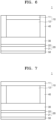
- the first inactive member 40 may be disposed on one side of the cathode layer 10.
- the first inactive member 40 may be disposed on one side of the cathode active material layer 12 and one side of the cathode current collector 11.
- the first inactive member 40 may be disposed on one side of the cathode active material layer 12 and may be disposed between the solid electrolyte layer 30 and the cathode current collector 11 opposite to the solid electrolyte layer 30.
- the first inactive member 40 may not be disposed on one side of the cathode current collector 11.
- the first inactive member 40 may be provided, and thus cracks of the solid electrolyte layer 30 may be prevented during manufacturing and/or charging/discharging of the all-solid secondary battery 1, thereby improving the cycle characteristics of the all-solid secondary battery 1.
- non-uniform pressure may be applied to the solid electrolyte layer 30 in contact with the cathode layer 10, which causes cracks in the solid electrolyte layer 30 and increases a possibility that a short circuit occurs due to the growth of a lithium metal through the cracks.
- a thickness T2 of the first inactive member 40 may be greater than or equal to a thickness T1 of the cathode active material layer 12.
- the thickness T2 of the first inactive member 40 may be substantially equal to a thickness T3 of the cathode layer 10.
- the thickness T2 of the first inactive member 40 may be equal to the thickness T3 of the cathode layer 10, uniform pressure may be applied to the cathode layer 10 and the solid electrolyte layer 30, and the cathode layer 10 may be in sufficiently close contact with the solid electrolyte layer 30 so that interfacial resistance between the cathode layer 10 and the solid electrolyte layer 30 may be reduced.
- the solid electrolyte layer 30 may be sufficiently sintered during a press manufacturing process of the all-solid secondary battery 1, thereby reducing internal resistance of the solid electrolyte layer 30 and the all-solid secondary battery 1 including the same.
- the first inactive member 40 may surround a side of the cathode layer 10 and may be in contact with the solid electrolyte layer 30.
- the first inactive member 40 may surround the side of the cathode layer 10 and may be in contact with the solid electrolyte layer 30, and thus cracks of the solid electrolyte layer 30 may be effectively suppressed from being caused in the solid electrolyte layer 30 not in contact with the cathode layer 10 due to a pressure difference during a pressing process.
- the first inactive member 40 may surround the side of the cathode layer 10 and may be separated from the anode layer 20, more specifically, the first anode active material layer 22.
- the first inactive member 40 may surround the side of the cathode layer 10, may be in contact with the solid electrolyte layer 30, and may be separated from the anode layer 20. In some embodiments, a possibility that a short circuit occurs due to physical contact between the cathode layer 10 and the first anode active material layer 22 may be suppressed, or a possibility that a short circuit occurs due to overcharging of lithium may be suppressed.
- the first inactive member 40 may be disposed on one side of the cathode active material layer 12 and concurrently may also be disposed on one side of the cathode current collector 11, thereby more effectively suppressing a possibility that a short circuit occurs due to contact between the cathode current collector 11 and the anode layer 20.
- the first inactive member 40 (40a or 40b) may extend from one side of the cathode layer 10 to an end portion of the solid electrolyte layer 30.
- the first inactive member 40 may extend to the end portion of the solid electrolyte layer 30, and thus cracks may be suppressed from occurring in the end portion of the solid electrolyte layer 30.
- the end portion of the solid electrolyte layer 30 may be an outermost portion in contact with a side of the solid electrolyte layer 30.
- the first inactive member 40 may extend to the outermost portion in contact with the side of the solid electrolyte layer 30.
- the first inactive member 40 may be separated from the anode layer 20, for example, the first anode active material layer 22.
- the first inactive member 40 extends to the end portion of the solid electrolyte layer 30 but is not in contact with the anode layer 20.
- the first inactive member 40 may fill, for example, a space extending from one side of the cathode layer 10 to the end portion of the solid electrolyte layer 30.
- a width W2 of the first inactive member 40 extending from one side of the cathode layer 10 to the end portion of the solid electrolyte layer 30 may be in a range of, for example, about 1% to about 30%, about 1% to about 25%, about 1% to about 20%, about 1% to about 15%, about 1% to about 10%, or about 1% to about 5% of a width W1 between one side of the cathode layer 10 and the other side opposite to the one side.
- a width of the first inactive member 40 extending from one side of the cathode layer 10 to the end portion of the solid electrolyte layer 30 may be, for example, in a range of about 1% to about 30%, about 3% to about 30%, about 5% to about 30%, about 5% to about 20%, about 5% to about 15%, or about 5% to about 10% of a width between one side of the cathode layer 10 and the other side opposite to the one side. If the width W2 of the first inactive member 40 is excessively wide, an energy density of the all-solid secondary battery 1 may be reduced. If the width W2 of the first inactive member 40 may be excessively narrow, an effect of arranging the first inactive member 40 may be insignificant.
- An area S1 of the cathode layer 10 such as an area S1 of the positive electrode active material layer 12 (e.g. a cross-sectional area S1 of the positive electrode layer 10, or a cross-sectional area S1 of the positive electrode active material layer 12, relative to a stacking direction or thickness direction of the all-solid secondary battery 1), may be smaller than an area S3 of the solid electrolyte layer 30 (e.g. a cross-sectional area S3 of the solid electrolyte layer 30 relative to a stacking direction or thickness direction of the all-solid secondary battery 1) in contact with the cathode layer 10 (or the positive electrode active material layer 12).
- the first inactive member 40 having flame retardancy may be disposed to surround the side of the cathode layer 10 (or the positive electrode active material layer 12) to compensate for an area difference between the cathode layer 10 (or the positive electrode active material layer 12) and the solid electrolyte layer 30.
- An area S2 of the first inactive member 40 e.g.
- a cross-sectional area S2 of first inactive member 40 relative to a stacking direction or thickness direction of the all-solid secondary battery 1) having flame retardancy may compensate for a difference between the area S1 of the cathode layer 10 (or the positive electrode active material layer 12) and the area S3 of the solid electrolyte layer 30, and thus cracks of the solid electrolyte layer 30 caused by a pressure difference during a pressing process may be effectively suppressed.
- the sum of the area S1 of the cathode layer 10 (or the positive electrode active material layer 12) and the area S2 of the first inactive member 40 may be equal to the area S3 of the solid electrolyte layer 30.
- the area S1 of the cathode layer 10 may be, for example, less than 100%, 99% or less, 98% or less, 97% or less, 96% or less, or 95% or less of the area S3 of the solid electrolyte layer 30.
- the area S1 of the cathode layer 10 (or the positive electrode active material layer 12) may be in a range of, for example, about 50% to less than about 100%, about 50% to about 99%, about 55% to about 98%, about 60% to about 97%, about 70% to about 96%, about 80% to about 95%, or about 85% to about 95% of the area S3 of the solid electrolyte layer 30.
- the area S1 of the cathode layer 10 (or the positive electrode active material layer 12) is greater than or equal to the area S3 of the solid electrolyte layer 30, a possibility that a short circuit occurs due to physical contact between the cathode layer 10 (or the positive electrode active material layer 12) and the first anode active material layer 22 may be increased, or a possibility that a short circuit occurs due to overcharging of lithium may be increased.
- the area S1 of the cathode layer 10 may be equal to, for example, an area of the cathode active material layer 12.
- the area S1 of the cathode layer 10 may be equal to, for example, an area of the cathode current collector 11.
- the area S2 of the first inactive member 40 may be, for example, 50% or less, 40% or less, 30% or less, 20% or less, or 10% or less of the area S1 of the cathode layer 10 (or the positive electrode active material layer 12).
- the area S2 of the first inactive member 40 may be in a range of, for example, about 1% to about 50%, about 5% to about 40%, about 5% to about 30%, about 5% to about 20%, or about 5% to about 15% of the area S1 of the cathode layer 10.
- the area S1 of the cathode layer 10 may be smaller than an area S4 of the anode current collector 21 (e.g. a cross-sectional area S4 of the negative electrode current collector 21 relative to a stacking direction or thickness direction of the all-solid secondary battery 1).
- the area S1 of the cathode layer 10 (or the positive electrode active material layer 12) may be, for example, less than 100%, 99% or less, 98% or less, 97% or less, 96% or less, or 95% or less of the area S4 of the anode current collector 21.
- the area S1 of the cathode layer 10 may be in a range of, for example, about 50% to less than about 100%, about 50% to about 99%, about 55% to about 98%, about 60% to about 97%, about 70% to about 96%, about 80% to about 95%, or about 85% to about 95% of the area S4 of the anode current collector 21.
- the area S4 of the anode current collector 21 may be equal to, for example, an area of the anode layer 20 (e.g. a cross-sectional area of the negative electrode layer 20 relative to a stacking direction or thickness direction of the all-solid secondary battery 1).
- the area S4 of the anode current collector 21 may be equal to, for example, an area of the first anode active material layer 22 (e.g. a cross-sectional area of the first negative electrode active material layer 22 relative to a stacking direction or thickness direction of the all-solid secondary battery 1).
- the "equal" area, length, width, thickness, and/or shape as used herein encompass all cases of having “substantially equal” area, length, width, thickness, and/or shape except for a case in which areas, lengths, widths, thicknesses, and/or shapes are intentionally expressed as being different.
- the "equal" area, length, width, and/or thickness encompass a range in which an unintentional difference in area, length, width, and/or thickness between comparison objects is less than 3%, less than 1%, less than 0.5%, or less than 0.1%.
- a thickness of the first inactive member 40 may be greater than, for example, a thickness of the first anode active material layer 22.
- the thickness of the first anode active material layer 22 may be, for example, 50% or less, 40% or less, 30% or less, 20% or less, or 10% or less of the thickness of the first inactive member 40.
- the thickness of the first anode active material layer 22 is in a range of, for example, about 1% to about 50%, about 1% to about 40%, about 1% to about 30%, about 1% to about 20%, or about 1% to about 10% of the thickness of the first inactive member 40.
- the anode layer 20 may include the anode current collector 21 and the first anode active material layer 22 disposed on one side of the anode current collector 21.
- the other side opposite to one side of the anode current collector 21 may be free of the first anode active material layer 22.
- the first anode active material layer 22 may be disposed on only one side of the anode current collector 21, and the first anode active material layer 22 is not disposed on the other side.
- the first inactive member 40 may be a gasket.
- the gasket may be used as the first inactive member 40, thereby effectively suppressing cracks of the solid electrolyte layer 30 caused due to a pressure difference during a pressing process.
- the first inactive member 40 may have, for example, a single layer structure. In other embodiments, although not shown in the drawings, the first inactive member 40 may have a multi-layer structure. In the first inactive member 40 having the multi-layer structure, respective layers may have different compositions. The first inactive member 40 having the multi-layer structure may have, for example, a two-layer structure, a three-layer structure, a four-layer structure, or a five-layer structure. The first inactive member 40 having the multi-layer structure may include, for example, one or more adhesive layers and one or more support layers.
- the adhesive layer may effectively prevent the cathode layer 10 from being separated from the solid electrolyte layer 30 due to a change in volume of the cathode layer 10 which is caused during a charging/discharging process of the all-solid secondary battery 1.
- the adhesive layer may provide a binding force between the support layer and other layers to improve film strength of the first inactive member 40.
- the support layer may provide a support force to the first inactive member 40, may prevent non-uniformity of pressure applied to the solid electrolyte layer 30 during a pressing process or a charging/discharging process, and may prevent shape deformation of the all-solid secondary battery 1 to be manufactured.
- an all-solid secondary battery 1 may include a cathode layer 10, anode layers 20 (20a and 20b), and solid electrolyte layers 30 (30a and 30b) disposed between the cathode layer 10 and the anode layers 20.
- the cathode layer 10 may include a cathode current collector 11 and each of a first cathode active material layer 12a and a second cathode active material layer 12b disposed on two sides of the cathode current collector 11.
- the solid electrolyte layers 30 may include a first solid electrolyte layer 30a in contact with the first cathode active material layer 12a and a second solid electrolyte layer 30b in contact with the second cathode active material layer 12b, respectively.
- the anode layers 20 may include a first anode layer 20a in contact with the first solid electrolyte layer 30a and a second anode layer 20b in contact with the second solid electrolyte layer 30b, respectively.
- First inactive members 40 may be disposed between the first solid electrolyte layer 30a and the second solid electrolyte layer 30b opposite to each other to surround a side of the cathode layer 10.
- the first inactive members 40 include, for example, a (1a) th inactive member 40a in contact with the first solid electrolyte layer 30a and a (1b) th inactive member 40b in contact with the second solid electrolyte layer 30b.
- the all-solid secondary battery 1 may have a bi-cell structure.
- the all-solid secondary battery 1 may have such a bi-cell structure, and thus the solid electrolyte layers 30 and the anode layers 20 may be symmetrically disposed opposite to each other with respect to the cathode layer 10, thereby more effectively suppressing structural deformation or the like due to pressure applied during manufacturing of the all-solid secondary battery 1.
- cracks of the solid electrolyte layer 30 may be suppressed during a manufacturing process and/or a charging/discharging process of the all-solid secondary battery 1 to prevent a short circuit of the all-solid secondary battery 1, thereby further improving the cycle characteristics of the all-solid secondary battery 1.
- only one cathode current collector 11 may be used for a plurality of cathode active material layers 12a and 12b, and thus an energy density of the all-solid secondary battery 1 may be increased.
- the first inactive member 40 may be, for example, a flame retardant inactive member.
- the flame retardant inactive member may provide flame retardancy to prevent a possibility of thermal runaway and ignition of the all-solid secondary battery 1.
- the safety of the all-solid secondary battery 1 may be further improved.
- the flame retardant inactive member may absorb residual moisture in the all-solid secondary battery 1, and thus the deterioration of the all-solid secondary battery 1 may be prevented to improve the lifespan characteristics of the all-solid secondary battery 1.
- the flame retardant inactive member may include, for example, a matrix and a filler.
- the matrix may include, for example, a substrate and a reinforcement material.
- the matrix may include, for example, a fibrous substrate and a fibrous reinforcement material.
- the matrix may include the substrate and thus may have elasticity. In some embodiments, the matrix may effectively receive a change in volume of the all-solid secondary battery 1 during charging/discharging and may be disposed at any one of various positions.
- the substrate included in the matrix may include, for example, a first fibrous material.
- the substrate may include the first fibrous material, thereby effectively receiving a change in volume of the cathode layer 10 caused during a charging/discharging process of the all-solid secondary battery 1 and effectively suppressing the deformation of the first inactive member 40 due to the change in volume of the cathode layer 10.
- the first fibrous material may be, for example, a material having an aspect ratio of 5 or more, 20 or more, or 50 or more.
- the first fibrous material may be, for example, a material having an aspect ratio of about 5 to about 1,000, about 20 to about 1,000, or about 50 to about 1,000.
- the first fibrous material may be, for example, an insulating material.
- the first fibrous material may be the insulating material, thereby effectively preventing a short circuit between the cathode layer 10 and the anode layer 20 caused by lithium dendrites or the like generated during charging/discharging of the all-solid secondary battery 1.
- the first fibrous material may include, for example, at least one selected from a pulp fiber, an insulating polymer fiber, and an ion-conductive polymer fiber.
- the matrix may include the reinforcement material, and thus strength of the matrix may be improved. In some embodiments, the matrix may prevent an excessive change in volume during charging/discharging of the all-solid secondary battery 1 and prevent the deformation of the all-solid secondary battery 1.
- the reinforcement material included in the matrix may include, for example, a second fibrous material.
- the reinforcement material may include the second fibrous material, and thus strength of the matrix may be more uniformly increased.
- the second fibrous material may be, for example, a material having an aspect ratio of 3 or more, 5 or more, or 10 or more.
- the second fibrous material may be, for example, a material having an aspect ratio of about 3 to about 100, about 5 to about 100, or about 10 to about 100.
- the second fibrous material may be, for example, a flame retardant material.
- the second fibrous material may be the flame retardant material, thereby effectively suppressing ignition due to thermal runaway caused by an external impact or a charging/discharging process of the all-solid secondary battery 1.
- the second fibrous material may be, for example, a glass fiber, a metal oxide fiber, a ceramic fiber, or the like.
- the flame retardant inactive member may include the filler in addition to the matrix.
- the filler may be disposed inside the matrix, on a surface of the matrix, or both inside and on the surface.
- the filler may be, for example, an inorganic material.
- the filler included in the flame retardant inactive member may be, for example, a moisture getter.
- the filler may adsorb moisture at a temperature of, for example, less than 100 °C to remove moisture remaining in the all-solid secondary battery 1, thereby preventing the deterioration of the all-solid secondary battery 1.
- the filler may release adsorbed moisture to effectively suppress ignition of the all-solid secondary battery 1.
- the filler may be, for example, a flame retardant.
- the filler may be, for example, metal hydroxide having moisture adsorbability.
- Metal hydroxide included in the filler may be, for example, Mg(OH) 2 , Fe(OH) 3 , Sb(OH) 3 , Sn(OH) 4 , Ti(OH) 3 , Zr(OH) 4 , Al(OH) 3 , or a combination thereof.
- a content of the filler included in the flame retardant inactive member may be in a range of, for example, about 10 parts by weight to about 80 parts by weight, about 20 parts by weight to about 80 parts by weight, about 30 parts by weight to about 80 parts by weight, about 40 parts by weight to about 80 parts by weight, about 50 parts by weight to about 80 parts by weight, about 60 parts by weight to about 80 parts by weight, or about 65 parts by weight to about 80 parts by weight with respect to about 100 parts by weight of the first inactive member 40 having flame retardancy.
- the flame retardant inactive member may further include, for example, a binder.
- the binder may include, for example, a curable polymer or a non-curable polymer.
- the curable polymer is a polymer that is cured by heat and/or pressure.
- the curable polymer may be, for example, a solid at room temperature.
- the first inactive member 40 having flame retardancy may include, for example, a thermosetting film and/or a cured product thereof.
- a thermosetting polymer may be, for example, TSA-66 manufactured by TORAY INDUSTRIES, INC.
- the flame retardant inactive member may additionally include other materials in addition to the above-described substrate, reinforcement material, filler, and binder.
- the flame retardant inactive member may further include at least one selected from, for example, paper, an insulating polymer, an ion-conductive polymer, an insulating inorganic material, an oxide-based solid electrolyte, and a sulfide-based solid electrolyte.
- the insulating polymer may be, for example, an olefin-based polymer such as PP or PE.
- a density of the substrate or the reinforcement material included in the flame retardant inactive member may be in a range of, for example, about 10% to about 300%, about 10% to about 150%, about 10% to about 140%, about 10% to about 130%, or about 10% to about 120% of a density of a cathode active material included in a cathode active material layer 12.
- the first inactive member 40 may be a member that does not include an electrochemically active material, for example, an electrode active material.
- An electrode active material may be a material that absorbs/desorbs lithium.
- the first inactive member 40 may be a member consisting of a material that is used in the art and is a material other than an electrode active material.
- the anode layer 20 may include a first anode active material layer 22.
- the first anode active material layer 22 may include, for example, an anode active material and a binder.
- the anode active material included in the first anode active material layer 22 may be, for example, an anode material that may form an alloy or a compound together with lithium.
- the anode active material included in the first anode active material layer 22 may have, for example, a particle form.
- the anode active material having the particle form may have an average particle diameter of, for example, 4 ⁇ m or less, 3 ⁇ m or less, 2 ⁇ m or less, 1 ⁇ m or less, 500 nm or less, 300 nm or less, or 100 nm or less.
- the anode active material having the particle form may have an average particle diameter of, for example, about 10 nm to about 4 ⁇ m, about 10 nm to about 3 ⁇ m, about 10 nm to about 2 ⁇ m, about 10 nm to about 1 ⁇ m, about 10 nm to about 500 nm, about 10 nm to about 300 nm, or about 10 nm to about 100 nm.
- the anode active material may have an average particle diameter within such a range, and thus reversible absorbing and/or desorbing of lithium may be more easily performed during charging/discharging.
- the average particle diameter of the anode active material may be, for example, a median diameter (D50) measured using a laser type particle size distribution meter.
- the anode active material included in the first anode active material layer 22 may include, for example, at least one selected from a carbon-based anode active material and a metal or metalloid anode active material.
- the carbon-based anode active material may include, for example, amorphous carbon, crystalline carbon, porous carbon, or a combination thereof.
- the carbon-based anode active material may be amorphous carbon.
- Amorphous carbon may be, for example, CB, AB, furnace black (FB), KB, graphene or the like but is not necessarily limited thereto. Any material classified as amorphous carbon in the art may be used.
- Amorphous carbon may be carbon that does not have crystallinity or has very low crystallinity and is distinguished from crystalline carbon or graphite-based carbon.
- the carbon-based anode active material may be, for example, porous carbon.
- a pore volume of porous carbon may be in a range of, for example, about 0.1 cc/g to about 10.0 cc/g, about 0.5 cc/g to about 5 cc/g, or about 0.1 cc/g to about 1 cc/g.
- An average pore diameter of porous carbon may be in a range of, for example, about 1 nm to about 50 nm, about 1 nm to about 30 nm, or about 1 nm to about 10 nm.
- a BET specific surface area of porous carbon may be in a range of, for example, about 100 m 2 /g to about 3,000 m 2 /g. The BET specific surface area of porous carbon may be measured, for example, according to ISO 9277:2022.
- the metal or metalloid anode active material may include at least one selected from the group consisting of gold (Au), platinum (Pt), palladium (Pd), silicon (Si), silver (Ag), aluminium (Al), bismuth (Bi), tin (Sn), and zinc (Zn), but one or more embodiments are not necessarily limited thereto.
- Any material, which is used as a metal anode active material or a metalloid anode active material forming an alloy or a compound together with lithium in the art may be used.
- nickel (Ni) may not form an alloy with lithium, and thus nickel (Ni) may not be a metal anode active material.
- the first anode active material layer 22 may include one anode active material or a mixture of a plurality of different anode active materials.
- the first anode active material layer 22 may include only amorphous carbon or at least one selected from the group consisting of gold (Au), platinum (Pt), palladium (Pd), silicon (Si), silver (Ag), aluminium (Al), bismuth (Bi), tin (Sn), and zinc (Zn).
- the first anode active material layer 22 may include a mixture of amorphous carbon and at least one selected from the group consisting of gold (Au), platinum (Pt), palladium (Pd), silicon (Si), silver (Ag), aluminium (Al), bismuth (Bi), tin (Sn), and zinc (Zn).
- a mixing ratio of the mixture of amorphous carbon to gold or the like may be in a range of, for example, about 99:1 to about 1:99, about 10:1 to about 1:2, about 5:1 to about 1:1, or about 4:1 to about 2:1 based on a weight ratio but is not necessarily limited to such a range and is selected according to the required characteristics of the all-solid secondary battery 1.
- the anode active material may have such a composition, and thus the cycle characteristics of the all-solid secondary battery 1 may be further improved.
- the anode active material included in the first anode active material layer 22 may include, for example, a mixture of first particles consisting of amorphous carbon and second particles consisting of a metal or a metalloid.
- a metal or metalloid may include, for example, gold (Au), platinum (Pt), palladium (Pd), silicon (Si), silver (Ag), aluminum (Al), bismuth (Bi), tin (Sn), or the like.
- a metalloid is a semiconductor.
- a content of the second particles may be in a range of about 1 wt% to about 99 wt%, about 1 wt% to about 60 wt%, about 8 wt% to about 60 wt%, about 10 wt% to about 50 wt%, about 15 wt% to about 40 wt%, or about 20 wt% to about 30 wt% with respect to the total weight of the mixture.
- the second particles may have a content within such a range, for example, and thus the cycle characteristics of the all-solid secondary battery 1 may be further improved.
- the first anode active material layer 22 may include a composite anode active material.
- the composite anode active material may include, for example, a carbon-based support and a metal-based anode active material supported on the carbon-based support.
- the composite anode active material may have such a structure so that the localization of the metal-based anode active material in the first anode active material layer 22 may be prevented, and the uniform distribution thereof may be obtained.
- the cycle characteristics of the all-solid secondary battery 1 including the first anode active material layer 22 may be further improved.
- the metal-based anode active material supported on the carbon-based support may include, for example, a metal, a metal oxide, a composite of a metal and a metal oxide, or a combination thereof.
- the metal may include gold (Au), platinum (Pt), palladium (Pd), silicon (Si), silver (Ag), aluminium (Al), bismuth (Bi), tin (Sn), tellurium (Te), zinc (Zn), and the like.
- metal oxide examples include gold (Au) oxide, platinum (Pt) oxide, palladium (Pd) oxide, silicon (Si) oxide, silver (Ag) oxide, aluminium (Al) oxide, bismuth (Bi) oxide, tin (Sn) oxide, tellurium (Te) oxide, zinc (Zn) oxide, and the like.
- the metal oxide may include, for example, Au x O y , wherein 0 ⁇ x ⁇ 2 and 0 ⁇ y ⁇ 3, Pt x O y , wherein 0 ⁇ x ⁇ 1 and 0 ⁇ y ⁇ 2, Pd x O y , wherein 0 ⁇ x ⁇ 1 and 0 ⁇ y ⁇ 1, Si x O y , wherein 0 ⁇ x ⁇ 1 and 0 ⁇ y ⁇ 2, Ag x O y , wherein 0 ⁇ x ⁇ 2 and 0 ⁇ y ⁇ 1, Al x O y , wherein 0 ⁇ x ⁇ 2 and 0 ⁇ y ⁇ 3, Bi x O y , wherein 0 ⁇ x ⁇ 2 and 0 ⁇ y ⁇ 3, Sn x O y , wherein 0 ⁇ x ⁇ 1 and 0 ⁇ y ⁇ 2, Te x O y , wherein 0 ⁇ x ⁇ 1 and 0 ⁇ y ⁇ 3, Zn x O y , wherein 0 ⁇ x ⁇ 1 and 0 ⁇ y ⁇ 1, or a combination thereof.
- the composite of the metal and the metal oxide may include, for example, a composite of Au and Au x O y , wherein 0 ⁇ x ⁇ 2 and 0 ⁇ y ⁇ 3, a composite of Pt and Pt x O y , wherein 0 ⁇ x ⁇ 1 and 0 ⁇ y ⁇ 2, a composite of Pd and Pd x O y , wherein 0 ⁇ x ⁇ 1 and 0 ⁇ y ⁇ 1, a composite of Si and Si x O y , wherein 0 ⁇ x ⁇ 1 and 0 ⁇ y ⁇ 2, a composite of Ag and Ag x O y , wherein 0 ⁇ x ⁇ 2 and 0 ⁇ y ⁇ 1, a composite of Al and Al x O y , wherein 0 ⁇ x ⁇ 2 and 0 ⁇ y ⁇ 3, a composite of Bi and Bi x O y , wherein 0 ⁇ x ⁇ 2 and 0 ⁇ y ⁇ 3, a composite of Sn and Sn x O y , wherein 0 ⁇ x ⁇ 1 and 0 ⁇ y ⁇ 2,
- the carbon-based support may include, for example, amorphous carbon.
- amorphous carbon may include CB, AB, furnace black (FB), KB, graphene, activated carbon, CNFs, CNTs, and the like, but one or more embodiments are not necessarily limited thereto. Any material may be used as long as the material may be classified as amorphous carbon in the art.
- the amorphous carbon may be carbon that has no crystallinity or very low crystallinity and may be distinguished from crystalline carbon or graphite-based carbon.
- a carbonaceous material may be, for example, a carbon-based anode active material.
- the composite anode active material may have, for example, a particle form.
- a particle diameter (e.g. an average particle diameter, such as D50) of the composite anode active material having the particle form may be, for example, in a range of about 10 nm to about 4 ⁇ m, about 10 nm to about 1 ⁇ m, about 10 nm to about 500 nm, about 10 nm to about 200 nm, or about 10 nm to about 100 nm.
- the composite anode active material may have a particle diameter in such a range, and thus the reversible absorbing and/or desorbing of lithium may become easier during charging/discharging.
- the metal-based anode active material supported on the carbon-based support may have, for example, a particle form.
- a particle diameter of the metal-based anode active material may be, for example, in a range of about 1 nm to about 200 nm, about 1 nm to about 150 nm, about 5 nm to about 100 nm, or about 10 nm to about 50 nm.
- the carbon-based support may have, for example, a particle form.
- a particle diameter of the carbon-based support may be, for example, in a range of about 10 nm to about 2 ⁇ m, about 10 nm to about 1 ⁇ m, about 10 nm to about 500 nm, about 10 nm to about 200 nm, or about 10 nm to about 100 nm.
- the carbon-based support may have a particle diameter in such a range and thus may be more uniformly disposed in the first anode active material layer 22.
- the carbon-based support may include, for example, nanoparticles having a particle diameter of 500 nm or less.
- the particle diameter of the composite anode active material, the particle diameter of the metal-based anode active material, and the particle diameter of the carbon-based support may each be, for example, an average particle diameter.
- the average particle diameter may be, for example, a median diameter (D50) measured by using a laser type particle size distribution meter.
- the average particle diameter may be determined automatically by using software, for example, from an electron microscope image or may be manually determined according to a manual.
- the binder included in the first anode active material layer 22 may be, for example, SBR, polytetrafluoroethylene, polyvinylidene fluoride, PE, a vinylidene fluoride/hexafluoropropylene copolymer, polyacrylonitrile, polymethyl methacrylate, or the like but is not necessarily limited thereto. Any material used as a binder in the art may be used.
- the binder may include a single binder or a plurality of different binders.
- the first anode active material layer 22 may include the binder and thus is stabilized on the anode current collector 21. In other embodiments, cracks of the first anode active material layer 22 may be suppressed despite a change in volume and/or relative position of the first anode active material layer 22 during charging/discharging. For example, if the first anode active material layer 22 does not include a binder, the first anode active material layer 22 may be easily separated from the anode current collector 21.
- the anode current collector 21 may come into contact with the solid electrolyte layer 30, and thus a possibility of the occurrence of a short circuit may be increased.
- slurry in which materials constituting the first anode active material layer 22 are dispersed may be applied on the anode current collector 21 and dried to manufacture the first anode active material layer 22.
- the binder may be included in the first anode active material layer 22, thereby stably dispersing an anode active material in the slurry.
- clogging of a screen for example, clogging due to aggregates of the anode active material
- the first anode active material layer 22 may further include additives used in a conventional all-solid secondary battery, such as a filler, a coating agent, a dispersant, and an ion-conductive adjuvant.
- additives used in a conventional all-solid secondary battery such as a filler, a coating agent, a dispersant, and an ion-conductive adjuvant.
- the first anode active material layer 22 may further include a solid electrolyte.
- the solid electrolyte may be, for example, a material selected from solid electrolytes included in the solid electrolyte layer 30.
- the solid electrolyte included in the first anode active material layer 22 may serve as a reaction point at which the formation of a lithium metal starts in the first anode active material layer 22 or may serve as a space for storing the formed lithium metal or as a path for transferring lithium ions.
- the solid electrolyte may be omitted.
- a content of the solid electrolyte may be high, for example, in a region adjacent to the solid electrolyte layer 30, and may be low in a region adjacent to the anode current collector 21.
- the solid electrolyte may have, for example, a concentration gradient in which a concentration decreases from the region adjacent to the solid electrolyte layer 30 to the region adjacent to the anode current collector 21.
- a ratio (B/A) of an initial charge capacity (B) of the first anode active material layer 22 to initial charge capacity (A) of the cathode active material layer 12 may be in a range of about 0.005 to about 0.45.
- the initial charge capacity of the cathode active material layer 12 may be determined by charging from a 1 st OCV up to a maximum charging voltage for Li/Li + .
- the initial charge capacity of the anode active material layer 22 may be determined by charging from a 2 nd OCV up to a voltage of about 0.01 V for Li/Li + .
- the maximum charging voltage may be determined according to types of cathode active materials.
- the maximum charging voltage may be, for example, about 1.5 V, about 2.0 V, about 2.5 V, about 3.0 V, about 3.5 V, about 4.0 V, about 4.2 V, or about 4.3 V.
- the maximum charging voltage of Li 2 S or a Li 2 S composite may be about 2.5 V for Li/Li + .
- the maximum charging voltage of Li 2 S or a Li 2 S composite may be about 3.0 V for Li/Li + .
- the ratio (B/A) of the initial charge capacity (B) of the first anode active material layer 22 to the initial charge capacity (A) of the cathode active material layer 12 may be in a range of, for example, about 0.01 to about 0.3, about 0.01 to about 0.2, or about 0.05 to about 0.1.
- the initial charge capacity (mAh) of the cathode active material layer 12 may be obtained by multiplying charge specific capacity (mAh/g) of the cathode active material layer 12 by mass (g) of the cathode active material of the cathode active material layer 12. If a plurality of types of cathode active materials are used, a value may be calculated by multiplying charge specific capacity by mass for each cathode active material, and the sum of such values may be the initial charge capacity of the cathode active material layer 12.
- the initial charge capacity of the first anode active material layer 22 may also be calculated in the same manner.
- the initial charge capacity of the first anode active material layer 22 may be obtained by multiplying charge specific capacity (mAh/g) of the first anode active material layer 22 by mass (g) of the anode active material of the first anode active material layer 22. If a plurality of types of anode active materials are used, a value may be calculated by multiplying charge specific capacity by mass for each anode active material, and the sum of such values may be the initial charge capacity of the first anode active material layer 22.
- the charge specific capacity of each of the cathode active material and the anode active material may be measured using an all-solid half-cell using a lithium metal as a counter electrode.
- the initial charge capacity of each of the cathode active material layer 12 and the first anode active material layer 22 may be directly measured at a constant current density of, for example, about 0.1 mA/cm 2 using an all-solid half-cell.
- the measurement may be performed at an operating voltage from the 1 st OCV to a maximum charging voltage, for example, about 3.0 V vs. Li/Li + .
- the measurement may be performed at an operating voltage from the 2 nd OCV to about 0.01 V for the anode, for example, a lithium metal.
- an all-solid half-cell including a cathode active material layer may be charged from the 1 st OCV to about 3.0 V at a constant current of about 0.1 mA/cm 2
- an all-solid half-cell including a first anode active material layer may be charged from the 2 nd OCV to about 0.01 V at a constant current of about 0.1 mA/cm 2
- a current density during constant current charging may be, for example, about 0.2 mA/cm 2 or about 0.5 mA/cm 2 .
- the all-solid half-cell including the cathode active material layer may be charged, for example, from the 1 st OCV to about 2.0 V, about 2.5 V, about 3.5 V, or about 4.0 V.
- a maximum charging voltage of a cathode active material layer may be determined according to a maximum voltage of a battery that satisfies safety conditions according to JIS C 8712:2015 of the Japanese Standard Association.
- the first anode active material layer 22 may become very thin, and thus lithium dendrites formed between the first anode active material layer 22 and the anode current collector 21 during a repeated charging/discharging process may collapse the first anode active material layer 22, which makes it difficult to improve the cycle characteristics of the all-solid secondary battery 1. If charge capacity of the first anode active material layer 22 is excessively increased, an energy density of the all-solid secondary battery 1 may be lowered, and internal resistance of the all-solid secondary battery 1 due to the first anode active material layer 22 may be increased, which makes it difficult to improve the cycle characteristics of the all-solid secondary battery 1.
- a thickness of the first anode active material layer 22 may be, for example, 50% or less, 40% or less, 30% or less, 20% or less, 10% or less, or 5% or less of a thickness of the cathode active material layer 12.
- the thickness of the first anode active material layer 22 may be in a range of, for example, about 1% to about 50%, about 1% to about 40%, about 1% to about 30%, about 1% to about 20%, about 1% to about 10%, or about 1% to about 5% of the thickness of the cathode active material layer 12.
- the thickness of the first anode active material layer 22 may be in a range of, for example, about 1 ⁇ m to about 20 ⁇ m, about 2 ⁇ m to about 15 ⁇ m, or about 3 ⁇ m to about 10 ⁇ m. If the first anode active material layer 22 is excessively thin, lithium dendrites formed between the first anode active material layer 22 and the anode current collector 21 may collapse the first anode active material layer 22, which makes it difficult to improve the cycle characteristics of the all-solid secondary battery 1.
- the thickness of the first anode active material layer 22 is excessively increased, an energy density of the all-solid secondary battery 1 may be lowered, and internal resistance of the all-solid secondary battery 1 due to the first anode active material layer 22 may be increased, which makes it difficult to improve the cycle characteristics of the all-solid secondary battery 1. If the thickness of the first anode active material layer 22 is decreased, for example, the initial charge capacity of the first anode active material layer 22 may also be decreased.
- the all-solid secondary battery 1 further may include, for example, a second anode active material layer which, after the all-solid secondary battery 1 is charged, is disposed between the anode current collector 21 and the first anode active material layer 22.
- the second anode active material layer may be a metal layer including lithium or a lithium alloy.
- the metal layer may include lithium or a lithium alloy.
- the second anode active material layer may be the metal layer including lithium, and thus the second anode active material layer may serve as, for example, a lithium reservoir.
- the lithium alloy may be, for example, a Li-Al alloy, a Li-Sn alloy, a Li-In alloy, a Li-Ag alloy, a Li-Au alloy, a Li-Zn alloy, a Li-Ge alloy, a Li-Si alloy, or the like but is not limited thereto. Any material used as a lithium alloy in the art may be used.
- the second anode active material layer may consist of one selected from such alloys or lithium or may consist of one selected from a plurality of types of alloys.
- the second anode active material layer may be, for example, a plated layer. For example, during a charging process of the all-solid secondary battery 1, the second anode active material layer may be precipitated between the first anode active material layer 22 and the anode current collector 21.
- a thickness of the second anode active material layer may be in a range of, for example, about 1 ⁇ m to about 500 ⁇ m, about 1 ⁇ m to about 200 ⁇ m, about 1 ⁇ m to about 150 ⁇ m, about 1 ⁇ m to about 100 ⁇ m, or about 1 ⁇ m to about 50 ⁇ m but is not particularly limited. If the second anode active material layer is excessively thin, it is difficult for the second anode active material layer to serve as a lithium reservoir. If the second anode active material layer is excessively thick, there may be a possibility that the mass and volume of the all-solid secondary battery 1 are increased, and the cycle characteristics of the all-solid secondary battery 1 are rather deteriorated.
- the second anode active material layer in the all-solid secondary battery 1, for example, before the all-solid secondary battery 1 is assembled, the second anode active material layer may be disposed between the anode current collector 21 and the first anode active material layer 22. If the second anode active material layer is disposed between the anode current collector 21 and the first anode active material layer 22 before the all-solid secondary battery 1 is assembled, the second anode active material layer may be the metal layer including lithium and thus serves as a lithium reservoir. For example, before the all-solid secondary battery 1 is assembled, a lithium foil may be disposed between the anode current collector 21 and the first anode active material layer 22.
- the second anode active material layer may be precipitated by the all-solid secondary battery 1 being charged after being assembled, the second anode active material layer may not be included during assembling of the all-solid secondary battery 1, and thus an energy density of the all-solid secondary battery 1 may be increased.
- the all-solid secondary battery 1 is charged, the first anode active material layer 22 may be charged beyond the charge capacity thereof. For example, the first anode active material layer 22 may be overcharged. At the beginning period of charging, lithium may be absorbed in the first anode active material layer 22.
- the anode active material included in the first anode active material layer 22 may form an alloy or a compound together with lithium ions moving from the cathode layer 10.
- first anode active material layer 22 is charged beyond capacity thereof, for example, lithium may be precipitated on a rear side of the first anode active material layer 22, for example, between the anode current collector 21 and the first anode active material layer 22, and a metal layer corresponding to the second anode active material layer may be formed by the precipitated lithium.
- the second anode active material layer may be a metal layer mainly consisting of lithium (for example, metal lithium). Such a result may be obtained, for example, because the anode active material included in the first anode active material layer 22 may include a material that forms an alloy or a compound together with lithium.
- lithium in the first anode active material layer 22 and the second anode active material layer may be ionized to move toward the cathode layer 10.
- lithium in the all-solid secondary battery 1, lithium may be used as an anode active material.
- the first anode active material layer 22 may cover the second anode active material layer, and thus the first anode active material layer 22 may serve as a protective layer for the second anode active material layer, for example, the metal layer, and concurrently may serve to suppress precipitation growth of lithium dendrites.
- the cycle characteristics of the all-solid secondary battery 1 may be improved.
- the anode layer 20 for example, the anode current collector 21, the first anode active material layer 22, and a region therebetween, may be Li-free regions that do not include lithium (Li) in an initial state of the all-solid secondary battery 1 or in a state after the all-solid secondary battery 1 is fully discharged.
- the anode current collectors 21 may consist of, for example, a material that does not react with lithium, for example, does not form either an alloy or a compound with lithium.
- a material constituting the anode current collector 21 may be, for example, copper (Cu), stainless steel, titanium (Ti), iron (Fe), cobalt (Co), or nickel (Ni) but is not necessarily limited thereto. Any material used as an electrode current collector in the art may be used.
- the anode current collector 21 may consist of at least one selected from the above-described metals, an alloy of two or more metals, or a coating material.
- the anode current collector 21 may be, for example, in the form of a plate or foil.
- the all-solid secondary battery 1 may further include a thin film including an element, which is capable of forming an alloy together with lithium, on one side of the anode current collector 21.
- the thin film may be disposed between the anode current collector 21 and the first anode active material layer 22.
- the thin film may include, for example, an element capable of forming an alloy together with lithium.
- the element capable of forming an alloy together with lithium may be, for example, gold, silver, zinc, tin, indium, silicon, aluminium, bismuth, or the like but is not necessarily limited thereto. Any element capable of forming an alloy together with lithium in the art may be used.
- the thin film may consist of at least one selected from the metals or an alloy of a plurality of metals.
- the thin film may be disposed on one side of the anode current collector 21, for example, thereby further flattening a precipitated form of the second anode active material layer precipitated between the thin film and the first anode active material layer 22 and further improving the cycle characteristics of the all-solid secondary battery 1.
- a thickness of the thin film may be in a range of, for example, about 1 nm to about 800 nm, about 10 nm to about 700 nm, about 50 nm to about 600 nm, or about 100 nm to about 500 nm. If the thickness of the thin film is less than about 1 nm, it may be difficult for the thin film to function. If the thin film is excessively thick, the thin film itself absorbs lithium, and thus an amount of lithium precipitated at an anode may decrease, resulting in a decrease in energy density of the all-solid secondary battery 1 and resulting in degradation in cycle characteristics of the all-solid secondary battery 1.
- the thin film may be disposed on the anode current collector 21 through, for example, a vacuum deposition method, a sputtering method, a plating method, or the like, and any method capable of forming a thin film in the art may be used.
- the anode current collector 21 may include, for example, a base film and a metal layer disposed on one side or two sides of the base film.
- the base film may include, for example, a polymer.
- the polymer may be, for example, a thermoplastic polymer.
- the polymer may include, for example, PET, PE, PP, PBT, PI, or a combination thereof.
- the polymer may be an insulating polymer.
- the base film may include an insulating thermoplastic polymer, and thus, if a short circuit occurs, the base film may soften or liquefy to interrupt the operation of a battery, thereby suppressing a rapid increase in current.
- the metal layer may include, for example, copper (Cu), stainless steel, titanium (Ti), iron (Fe), cobalt (Co), nickel (Ni), or an alloy thereof.
- the anode current collector 21 may additionally include a metal chip and/or a lead tab.
- the base film, metal layer, metal chip, and lead tab of the anode current collector 21 may be defined as for the above-described cathode current collector 11.
- the anode current collector 21 may have such a structure, and thus a weight of an anode may be reduced, thereby improving the energy density of the anode and a lithium battery.
- the all-solid secondary battery 1 (1a or 1b) may further include second inactive members 50 (50a, 50b, and 50c) disposed on the other sides of the anode current collectors 21 (21a and 21b).
- the second inactive member 50 may be different from the first inactive member 40 in that the second inactive member 50 may additionally include a conductive material to have conductivity.
- the second inactive member 50 may be, for example, a conductive flame retardant inactive member.
- the conductive material may include, for example, graphite, CB, AB, KB, Denka black, carbon fiber, CNTs, graphene, a metal fiber, a metal powder, or the like.
- Electronic conductivity at about 25 °C of the second inactive member 50 may be, for example, 100 times or more, 1,000 times or more, or 10,000 times or more electronic conductivity at about 25 °C of the first inactive member 40.
- the second inactive member 50 may include, for example, a matrix, a filler, and a conductive material.
- the matrix may include, for example, a substrate and a reinforcement material.
- the second inactive member 50 may further include a filler and a binder.
- a content of the conductive material included in the second inactive member 50 may be in a range of, for example, about 1 part by weight to about 30 parts by weight, about 1 part by weight to about 20 parts by weight, about 1 part by weight to about 15 parts by weight, about 1 part by weight to about 10 parts by weight, about 5 parts by weight to about 40 parts by weight, about 5 parts by weight to about 30 parts by weight, or about 5 parts by weight to about 35 parts by weight with respect to about 100 parts by weight of the second inactive member 50.
- a Young's modulus of the second inactive member 50 may be, for example, less than a Young's modulus of the anode current collector 21.
- the Young's modulus of the second inactive member 50 may be, for example, 50% or less, 30% or less, 10% or less, or 5% or less of the Young's modulus of the anode current collector 21.
- the Young's modulus of the second inactive member 50 may be in a range of, for example, about 0.01% to about 50%, about 0.1% to about 30%, about 0.1% to about 10%, or about 1% to about 5% of the Young's modulus of the anode current collector 21.
- the Young's modulus of the second inactive member 50 may be, for example, 100 MPa or less, 50 MPa or less, 30 MPa or less, 10 MPa or less, or 5 MPa or less.
- the Young's modulus of the second inactive member 50 may be in a range of, for example, about 0.01 MPa to about 100 MPa, about 0.1 MPa to about 50 MPa, about 0.1 MPa to about 30 MPa, about 0.1 MPa to about 10 MPa, or about 1 MPa to about 5 MPa.
- a Young's modulus of the second inactive member 50 may be measured by using DMA(Dynamic Mechanical Analyzer) or UTM(Universal Test Machine).
- a Young's modulus of the second inactive member 50 may be measured according to ASTM D638.
- the second inactive members 50 may have conductivity, and thus the second inactive member 50 may serve as the anode current collector 21.
- the second inactive members 50 may have the Young's modulus that is less than that of the anode current collector 21, and thus the second inactive members 50 may effectively receive a change in volume of the anode layer 20 during charging/discharging of the all-solid secondary battery 1.
- the second inactive members 50 may effectively relieve internal stress due to a change in volume of the all-solid secondary battery 1 during charging/discharging of the all-solid secondary battery 1, thereby improving the cycle characteristics of the all-solid secondary battery 1.
- a thickness of the second inactive member 50 may be greater than, for example, the thickness of the first anode active material layer 22.
- the second inactive member 50 may be thicker than the first anode active material layer 22, and thus the second inactive member 50 may more effectively receive a change in volume of the anode layer 20 during charging/discharging.
- the thickness of the first anode active material layer 22 may be, for example, 50% or less, 40% or less, 30% or less, 20% or less, or 10% or less of the thickness of the second inactive member 50.
- the thickness of the first anode active material layer 22 may be in a range of, for example, about 1% to about 50%, about 1% to about 40%, about 1% to about 30%, about 1% to about 20%, or about 1% to about 10% of the thickness of the second inactive member 50.
- the thickness of the second inactive member 50 may be in a range of, for example, about 1 ⁇ m to about 300 ⁇ m, about 10 ⁇ m to about 300 ⁇ m, about 50 ⁇ m to about 300 ⁇ m, or about 100 ⁇ m to about 200 ⁇ m. If the second inactive member 50 is excessively thin, an intended effect may be difficult to provide, and if the second inactive member 50 is excessively thick, an energy density of the all-solid secondary battery 1 may be decreased.
- a form of the second inactive member 50 is not particularly limited and may be selected according to a form of the all-solid secondary battery 1.
- the second inactive member 50 may have, for example, a sheet form, a rod form, or a gasket form.
- the second inactive member 50 may be disposed, for example, on one side or two sides of the all-solid secondary battery 1.
- the second inactive member 50 may be disposed, for example, between a plurality of stacked all-solid secondary batteries 1.
- the second inactive member 50 may be disposed between the plurality of stacked all-solid secondary batteries 1, on an uppermost side, and/or on a lowermost side.
- a ratio of a volume of the all-solid secondary battery 1 before charging to a volume of the all-solid secondary battery 1 after charging may be, for example, 15% or less, 10% or less, or 5% or less.
- a volume of the all-solid secondary battery 1 before charging may be measured at 25 °C before formation step by measuring thickness of the all-solid battery. Further, a volume of the all-solid secondary battery 1 after charging may be measured in the formation step by measuring thickness of the all-solid battery after completing 1 st charging step at 25 °C.
- An increase in volume of the anode layer 20 during charging of the all-solid secondary battery 1 may be offset by a decrease in volume of the cathode layer 10, and the second inactive member 50 may receive the change in volume of the anode layer 20, which mitigates a change in volume of the all-solid secondary battery 1 before and after charging.
- An energy density per unit volume of the all-solid secondary battery 1 may be in a range of, for example, about 500 Wh/L to about 900 Wh/L, about 500 Wh/L to about 800 Wh/L, or about 500 Wh/L to about 700 Wh/L.
- the energy density per unit weight of the all-solid secondary battery 1 may be in a range of, for example, about 350 Wh/g to about 600 Wh/g, about 350 Wh/g to about 580 Wh/g, about 350 Wh/g to about 570 Wh/g, or about 350 Wh/g to 550 WhIg.
- the all-solid secondary battery 1 may have an energy density within such a range, and thus an increased energy density may be provided as compared with a conventional secondary battery.
- the solid electrolyte layer 30 may include the solid electrolyte disposed between the cathode layer 10 and the anode layer 20.
- An electrolyte may include, for example, a solid electrolyte, a gel electrolyte, or a combination thereof.
- the solid electrolyte may include, for example, a sulfide-based solid electrolyte, an oxide-based solid electrolyte, a polymer solid electrolyte, or a combination thereof.
- the solid electrolyte may be, for example, the sulfide-based solid electrolyte.
- the sulfide-based solid electrolyte may be, for example, at least one selected from Li 2 S-P 2 S 5 , Li 2 S-P 2 S 5 -LiX, wherein X is a halogen element, Li 2 S-P 2 S 5 -Li 2 O, Li 2 S-P 2 S 5 -Li 2 O-LiI, Li 2 S-SiS 2 , Li 2 S-SiS 2 -LiI, Li 2 S-SiS 2 -LiBr, Li 2 S-SiS 2 -LiCl, Li 2 S-SiS 2 -B 2 S 3 -LiI, Li 2 S-SiS 2 -P 2 S 5 -LiI, Li 2 S-B 2 S 3 , Li 2 S-P 2 S 5 -Z m S n , wherein m and n are positive numbers
- the sulfide-based solid electrolyte may be prepared by treating a starting material such as Li 2 S or P 2 S 5 through a melt quenching method, a mechanical milling method, or the like. In other embodiments, after such treatment, heat treatment may be performed.
- the solid electrolyte may be in an amorphous state, a crystalline state, or a mixture state thereof.
- the solid electrolyte may be, for example, a material that includes at least sulfur (S), phosphorus (P), and lithium (Li) as constituent elements among the above-described sulfide-based solid electrolyte materials.
- the solid electrolyte may be a material including Li 2 S-P 2 S 5 .
- Li 2 S-P 2 S 5 is included as a sulfide-based solid electrolyte material that forms the solid electrolyte
- a mixing molar ratio of Li 2 S to P 2 S 5 may be in a range of about 20:80 to about 90:10, about 25:75 to about 90:10, about 30:70 to about 70:30, or about 40:60 to about 60:40.
- the sulfide-based solid electrolyte may include, for example, an argyrodite-type solid electrolyte represented by Formula 1 below.
- Formula 1 Li + 12-n-x A n+ X 2- 6-x Y - x
- A is P, As, Ge, Ga, Sb, Si, Sn, Al, In, Ti, V, Nb, or Ta
- X is S, Se, or Te
- Y is Cl, Br, I, F, CN, OCN, SCN, or N 3 , 1 ⁇ n ⁇ 5, and 0 ⁇ x ⁇ 2.
- the sulfide-based solid electrolyte may be, for example, an argyrodite-type compound including at least one selected from Li 7-x PS 6-x Cl x , wherein 0 ⁇ x ⁇ 2, Li 7-x PS 6-x Br x , wherein 0 ⁇ x ⁇ 2, and Li 7-x PS 6-x I x , wherein 0 ⁇ x ⁇ 2.
- the sulfide-based solid electrolyte may be, for example, an argyrodite-type compound including at least one selected from Li 6 PS 5 Cl, Li 6 PS 5 Br, and Li 6 PS 5 I.
- a density of the argyrodite-type solid electrolyte may be in a range of about 1.5 g/cc to about 2.0 g/cc.
- the argyrodite-type solid electrolyte may have a density of 1.5 g/cc or more so that the internal resistance of the all-solid secondary battery 1 may be reduced, and the penetration of Li into the solid electrolyte layer 30 may be effectively suppressed.
- the oxide-based solid electrolyte may be, for example, Li 1+x+y Al x Ti 2-x Si y P 3-y O 12 , wherein 0 ⁇ x ⁇ 2 and 0 ⁇ y ⁇ 3, BaTiO 3 , Pb(Zr,Ti)O 3 (PZT), Pb 1-x La x Zr 1-y Ti y 0 3 (PLZT), wherein 0 ⁇ x ⁇ 1 and 0 ⁇ y ⁇ 1, Pb(Mg 3 Nb 2/3 )O 3 -PbTiO 3 (PMN-PT), HfO 2 , SrTiO 3 , SnO 2 , CeO 2 , Na 2 O, MgO, NiO, CaO, BaO, ZnO, ZrO 2 , Y 2 O 3 , Al 2 O 3 , TiO 2 , SiO 2 , Li 3 PO 4 , Li x Ti y (PO 4 ) 3 , wherein 0 ⁇ x ⁇ 2 and 0 ⁇ y ⁇ 3, Li x Al
- LLZO Li 7 La 3 Zr 2 O 12
- M-doped LLZO Li 3+x La 3 Zr 2-a M a O 12
- the polymer solid electrolyte may include a mixture of a lithium salt and a polymer or may include a polymer having an ion-conductive functional group.
- the polymer solid electrolyte may be, for example, a polymer electrolyte that is in a solid state at a temperature of about 25 °C and a pressure of about 1 atm.
- the polymer solid electrolyte may not include, for example, a liquid.
- the polymer solid electrolyte may include a polymer, and the polymer may include, for example, polyethylene oxide (PEO), PVDF, vinylidene fluoride-hexafluoropropylene (PVDF-HFP), a poly(styrene-b-ethylene oxide) (PS-PEO) block copolymer, poly(styrene-butadiene), poly(styrene-isoprene-styrene), a poly(styrene-b-divinylbenzene) block copolymer, a poly(styrene-ethylene oxide-styrene) block copolymer, polystyrene sulfonate (PSS), polyvinyl fluoride (PVF), poly(methylmethacrylate) (PMMA), polyethylene glycol (PEG), polyacrylonitrile (PAN), polytetrafluoroethylene (PTFE), polyethylenedioxythiophene (PEDOT), polypyr
- the lithium salt may include, for example, LiPF 6 , LiBF 4 , LiSbF 6 , LiAsF 6 , LiClO 4 , LiCF 3 SO 3 , Li(CF 3 SO 2 ) 2 N, LiC 4 F 9 SO 3 , LiAlO 2 , LiAlCl 4 , or LiN(C x F 2x+1 SO 2 )(C y F 2y+1 SO 2 ), wherein x and y are each a natural number from 1 to 20, LiCI, Lil, or a mixture thereof.
- a polymer included in the polymer solid electrolyte may be, for example, a compound including 10 or more, 20 or more, 50 or more, or 100 or more repeating units.
- a weight average molecular weight of the polymer included in the polymer solid electrolyte may be, for example, 1,000 Daltons or more, 10,000 Daltons or more, 100,000 Daltons or more, or 1,000,000 Daltons or more.
- the gel electrolyte may include, for example, a polymer gel electrolyte.
- the gel electrolyte may have a gel state without including, for example, a polymer.
- the polymer gel electrolyte may include, for example, a liquid electrolyte and a polymer or may include an organic solvent and a polymer having an ion-conductive functional group.
- the polymer gel electrolyte may be, for example, a polymer electrolyte that is in a gel state at a temperature of about 25 °C and a pressure of about 1 atm.
- the polymer gel electrolyte may have, for example, a gel state without including a liquid.
- the liquid electrolyte used in the polymer gel electrolyte may include, for example, a mixture of an ionic liquid, a lithium salt, and an organic solvent, a mixture of a lithium salt and an organic solvent, a mixture of an ionic liquid and an organic solvent, or a mixture of a lithium salt and an ionic liquid.
- the polymer used in the polymer gel electrolyte may be selected from polymers used in a solid polymer electrolyte.
- the organic solvent may be selected from organic solvents used in a liquid electrolyte.
- the lithium salt may be selected from lithium salts used in a polymer solid electrolyte.
- the ionic liquid may refer to a salt in a liquid state at room temperature or a room-temperature molten salt that has a melting point at room temperature or less and consists of only ions.
- the ionic liquid may include, for example, at least one selected from compounds including a) one cation selected from an ammonium-based cation, a pyrrolidinium-based cation, pyridinium-based cation, a pyrimidinium-based cation, an imidazolium-based cation, a piperidinium-based cation, a pyrazolium-based cation, an oxazolium-based cation, a pyridazinium-base cation, a phosphonium-based cation, a sulfonium-based cation, a triazole-based cation, and a mixture thereof, and b) at least one anion selected from BF 4 - , PF
- the polymer solid electrolyte may be impregnated, for example, in a liquid electrolyte in a secondary battery to form a polymer gel electrolyte.
- the polymer gel electrolyte may further include inorganic particles.
- the polymer included in the polymer gel electrolyte may be, for example, a compound including 10 or more, 20 or more, 50 or more, or 100 or more repeating units.
- a weight average molecular weight of the polymer included in the polymer gel electrolyte may be, for example, 500 Daltons or more, 1,000 Daltons or more, 10,000 Daltons or more, 100,000 Daltons or more, or 1,000,000 Daltons or more.
- the solid electrolyte layer 30 may be impermeable to lithium polysulfide. In some embodiments, a side reaction between lithium polysulfide, which generates during charging/discharging of a sulfide-based cathode active material, and the anode layer 20, may be prevented. In some embodiments, the cycle characteristics of the all-solid secondary battery 1 including the solid electrolyte layer 30 may be improved.
- the solid electrolyte layer 30 may include, for example, a binder.
- the binder included in the solid electrolyte layer 30 may be, for example, SBR, polytetrafluoroethylene, polyvinylidene fluoride, PE, or the like but is limited thereto. Any material used as a binder in the art may be used.
- the binder of the solid electrolyte layer 30 may be the same as or different from the binder included in the cathode active material layer 12 and the first anode active material layer 22. The binder may be omitted.
- a content of the binder included in the solid electrolyte layer 30 may be in a range of about 0.1 wt% to about 10 wt%, about 0.1 wt% to about 5 wt%, about 0.1 wt% to about 3 wt%, about 0.1 wt% to about 1 wt%, about 0 wt% to about 0.5 wt%, or about 0 wt% to about 0.1 wt% with respect to the total weight of the solid electrolyte layer 30.
- LiI and AlI 3 were mixed at a molar ratio of 1:1 to prepare a first mixture.
- Li 2 S and the first mixture were mixed at a weight ratio of 40:20 to prepare a second mixture.
- the second mixture was mechanically milled by using a ball mill to prepare a Li 2 S-LiI-AlI 3 composite.
- Milling conditions included a temperature of 25 °C, a speed of 600 rpm, and milling time of 10 hours. Milling energy applied to a sample during milling was 28 G.
- the Li 2 S-LiI-AlI 3 composite and CNFs were mixed at a weight ratio of 60:10 to prepare a third mixture.
- the third mixture was mechanically milled by using a ball mill to prepare a Li 2 S-LiI-AlI 3 -CNF composite.
- Milling conditions included a temperature of 25 °C, a speed of 600 rpm, and milling time of 10 hours. Milling energy applied to a sample during milling was 28 G.
- the Li 2 S-LiI-AlI 3 -CNF composite was used as a sulfide-based cathode active material.
- LiI and AlI 3 were mixed at a molar ratio of 1:1 to prepare a first mixture.
- Li 2 S and the first mixture were mixed at a weight ratio of 40:20, and a mixture of Li 2 S, LiI, and AlI 3 , and CNFs were additionally mixed at a weight ratio of 60:10 to be used as a sulfide-based cathode active material.
- Example 1 Mono-cell all-solid secondary battery, sulfide-based cathode active material (Li 2 S-CNF composite), and first inactive member having flame retardancy
- a 10 ⁇ m-thick SUS foil was prepared as an anode current collector.
- CB having a primary particle diameter of about 30 nm and silver (Ag) particles having an average particle diameter of about 60 nm were prepared as anode active materials.
- the dried stack was pressed through a cold roll press at a pressure of 5 tonf/cm 2 and a speed of 5 m/sec to flatten a surface of a first anode active material layer of the stack.
- An anode layer was prepared through such a process.
- a thickness of a first anode active material layer included in the anode layer was about 15 ⁇ m.
- An area of the first anode active material layer was the same as an area of an anode current collector.
- Initial charge capacity of the anode layer was measured by using the above-described half-cell. Initial charge capacity of a first anode material layer was 2.3 mAh.
- a Li 2 S-CNF composite was prepared as a cathode active material.
- the Li 2 S-CNF composite was prepared according to a method disclosed in Electrochimica Acta, 230 (2017), pp. 279-284, except that a vapor grown carbon fiber (VGCF) was changed into CNFs.
- KB was prepared as a conductive agent. Such materials were mixed such that a weight ratio of the cathode active material, the solid electrolyte, and the conductive agent was 40:50:10, thereby preparing a cathode mixture.
- the cathode mixture was obtained through dry mixing using a ball mill.
- the cathode mixture obtained through the ball milling formed an ion-conductive and electron-conductive network.
- the cathode mixture was disposed on one side of a cathode current collector consisting of an aluminium foil or SUS having one side coated with carbon and was plate-pressed at a pressure of 200 MPa for 10 minutes, thereby preparing a cathode layer.
- a thickness of the cathode layer was about 120 ⁇ m.
- a thickness of a cathode active material layer was about 100 ⁇ m, and a thickness of the aluminium foil coated with carbon was about 20 ⁇ m.
- An area of the cathode active material layer was the same as an area of the cathode current collector.
- Initial charge capacity of the cathode layer was measured by using the above-described half-cell. Initial charge capacity of a cathode active material layer was 25 mAh.
- Example 1 a ratio (B/A) of an initial charge capacity (B) of the first anode active material layer to initial charge capacity (A) of a cathode active material layer was 0.09.
- the initial charge capacity of the cathode active material layer was determined by charging from a 1 st OCV up to a voltage of 2.8 V vs. Li/Li + .
- the initial charge capacity of the first anode active material layer was determined by charging from a 2 nd OCV up to a voltage of 0.01 V vs. Li/Li + .
- the ratio (B/A) of the initial charge capacity (B) of the first anode active material layer to the initial charge capacity (A) of the cathode active material layer measured under the same conditions as in Example 1 was in a range of 0.07 to 0.09.
- a double-sided anode was used in Example 7 and Example 8, and thus half of the initial charge capacity of the cathode layer was used to calculate the ratio (B/A).
- Octyl acetate was added to the prepared mixture and stirred to prepare slurry.
- the prepared slurry was applied on a 15 ⁇ m-thick nonwoven fabric placed on a 75 ⁇ m-thick PET substrate using a bar coater and was dried in air at a temperature 80 °C for 10 minutes, thereby obtaining a stack.
- the obtained stack was vacuum-dried at a temperature of 80 °C for 2 hours.
- a solid electrolyte layer was prepared through such a process.
- Slurry which was a mixture of a pulp fiber (cellulose fiber), a glass fiber, aluminium hydroxide (Al(OH) 3 ), an acrylic-based binder, and a solvent, was shaped into a gasket form, and the solvent was removed to prepare a flame retardant inactive member.
- a weight ratio of the pulp fiber (cellulose fiber), the glass fiber, the aluminium hydroxide (Al(OH) 3 ), and the acrylic-based binder was 20:8:70:2.
- a thickness of the flame retardant inactive member was about 120 ⁇ m.
- the solid electrolyte layer was disposed on the anode layer such that the first anode active material layer was in contact with the solid electrolyte layer, and the cathode layer was disposed on the solid electrolyte layer.
- a gasket which surrounded the cathode layer and was in contact with the solid electrolyte layer, was disposed around the cathode layer to prepare a stack.
- a thickness of the gasket was about 120 ⁇ m.
- the flame retardant inactive member was used as the gasket.
- the gasket was disposed in contact with a side of the cathode layer and the solid electrolyte layer.
- the cathode layer was disposed at a central portion of the solid electrolyte layer, and the gasket was disposed to surround the cathode layer and extend to an end portion of the solid electrolyte layer.
- An area of the cathode layer was about 90% of an area of the solid electrolyte layer, and the gasket was disposed in the entirety of the remaining area of 10% of the solid electrolyte layer on which the cathode layer was not disposed.
- the prepared stack was plate-pressed at a temperature 85 °C and a pressure of 500 MPa for 30 min.
- the solid electrolyte layer was sintered through such press treatment, and thus battery characteristics were improved.
- a thickness of the sintered solid electrolyte layer was about 45 ⁇ m.
- the area of the solid electrolyte layer was the same as an area of the anode layer.
- the pressed stack was introduced into a pouch and vacuum-sealed to manufacture an all-solid secondary battery. Portions of the cathode current collector and the anode current collector extended to the outside of the sealed all-solid secondary battery and were used as a cathode layer terminal and an anode layer terminal.
- Example 2 Sulfide-based cathode active material (Li 2 S-CNF composite), first inactive member having flame retardancy, and second inactive member having conductivity and flame retardancy
- An all-solid secondary battery was manufactured in the same manner as in Example 1, except that, before a pressed stack was introduced into a pouch, a conductive flame retardant member, which was in the form of a sheet having the same area and shape as the stack, was additionally disposed on an anode current collector of the pressed stack and was vacuum-sealed to manufacture the all-solid secondary battery.
- a conductive flame retardant inactive member sheet was prepared through the following method.
- the conductive flame retardant inactive member sheet may serve as an elastic sheet.
- Slurry which was a mixture of a pulp fiber (cellulose fiber), a glass fiber, aluminium hydroxide (Al(OH) 3 ), an acrylic-based binder, a conductive material (Denka black), and a solvent, was formed into a sheet form and then dried to prepare a flame retardant inactive member.
- a weight ratio of the pulp fiber (cellulose fiber), the glass fiber, the aluminium hydroxide (Al(OH) 3 ), the acrylic-based binder, and the conductive material was 20:8:50:2:20.
- a thickness of the flame retardant inactive member was about 120 ⁇ m. Before the prepared flame retardant inactive member was disposed on the anode current collector, vacuum heat treatment was performed thereon at a temperature of 80 °C for 5 hours to remove moisture or the like from the flame retardant inactive member.
- Example 3 Sulfide-based cathode active material (Li 2 S-CNF composite) and first inactive member having non-flame retardancy
- An all-solid secondary battery was manufactured in the same manner as in Example 1, except that a flame retardant inactive member was changed into a non-flame retardant inactive member.
- the non-flame retardant inactive member included a pulp fiber and an acrylic-based binder in a weight ratio of 98:2 and did not include a glass fiber and Al(OH) 3 .
- a thickness of the non-flame retardant inactive member was about 120 ⁇ m.
- Example 4 Sulfide-based cathode active material (Li 2 S-C-Li 6 PS 5 Cl composite) and first inactive member having flame retardancy
- An all-solid secondary battery was manufactured in the same manner as in Example 1, except that a Li 2 S-C-Li 6 PS 5 Cl composite was used as a cathode active material instead of a Li 2 S-CNF composite.
- the Li 2 S-C-Li 6 PS 5 Cl composite was prepared according to a method disclosed in Nano Lett. 2016, 16, 7, pp 4521-4527 .
- Example 5 Sulfide-based cathode active material (Li 2 S-CNF composite), first anode active material layer (Ag-supported carbon black), flame retardant first inactive member, flame retardant second inactive member
- An all-solid secondary battery was manufactured in the same manner as in Example 2, except that silver particle-supported CB below was used as an anode active material instead of a mixture of carbon black and silver particles.
- the silver-containing particles included silver particles, silver oxide (AgO) particles, and composite particles of silver (Ag) and silver oxide (AgO).
- a content of the silver-containing particles included in the composite anode active material was 5 wt%.
- An average particle diameter of the silver particles was 10 nm.
- Example 6 Sulfide-based cathode active material (Li 2 S-C-LiI composite), flame retardant first inactive member
- An all-solid secondary battery was manufactured in the same manner as in Example 1, except that a Li 2 S-C-LiI composite was used as a cathode active material instead of a Li 2 S-CNF composite.
- the Li 2 S-C-LiI composite was prepared according to a method disclosed in Nano Lett. 2016, 16, 7, pp 4521-4527 , except that Li 6 PS 5 Cl was changed into Lil.
- An all-solid secondary battery was manufactured in the same manner as in Example 1, except that a flame retardant inactive member (for example, a gasket) was not used if the all-solid secondary battery was manufactured.
- a flame retardant inactive member for example, a gasket
- Comparative Example 2 Oxide-based cathode active material and first inactive member having flame retardancy
- An all-solid secondary battery was manufactured in the same manner as in Example 1, except that a cathode including lithium transition metal oxide was used instead of a cathode including a Li 2 S cathode active material.
- a ratio (B/A) of an initial charge capacity (B) of a first anode active material layer to initial charge capacity (A) of a cathode active material layer was 0.09.
- the initial charge capacity of the cathode active material layer was determined by charging from a 1 st OCV up to a voltage of 4.25 V vs. Li/Li + .
- the initial charge capacity of the first anode active material layer was determined by charging from a 2 nd OCV up to a voltage of 0.01 V vs. Li/Li + .
- the cathode including the lithium transition metal oxide was provided through the following method.
- LiNi 0.8 Co 0.15 Al 0.05 O 2 (NCA) coated with Li 2 O-ZrO 2 (LZO) was prepared as a cathode active material.
- the cathode active material coated with LZO was prepared according to a method disclosed in Korean Patent Publication No. 10-2016-0064942 .
- a polytetrafluoroethylene (PTFE) binder (Teflon binder manufactured by DuPont) was prepared as a binder.
- CNFs were prepared as a conductive agent.
- the cathode sheet was disposed on one side of a cathode current collector consisting of an aluminium foil having one side coated with carbon and was plate-pressed at a pressure of 200 MPa for 10 minutes, thereby preparing a cathode layer.
- a thickness of the cathode layer was about 120 ⁇ m.
- a thickness of a cathode active material layer was about 100 ⁇ m, and a thickness of the aluminium foil coated with carbon was about 20 ⁇ m.
- An area of the cathode active material layer was the same as an area of the cathode current collector.
- Example 7 One bi-cell all-solid secondary battery, sulfide-based cathode active material (Li 2 S-CNF composite), and first inactive member having flame retardancy
- a cathode layer was prepared in the same manner as in Example 1, except that a cathode active material layer was prepared to be disposed on two sides of a cathode current collector.
- An entire thickness of the cathode layer was about 220 ⁇ m.
- a thickness of the cathode active material layer was about 100 ⁇ m, and a thickness of an aluminium foil coated with carbon was about 20 ⁇ m.
- the solid electrolyte layer was disposed on the anode layer such that a first anode active material layer was in contact with the solid electrolyte layer, and the cathode layer was disposed on the solid electrolyte layer.
- the cathode layer had a structure in which the cathode active material layer was disposed on each of two sides of the cathode current collector.
- a gasket was disposed around the cathode layer to surround the cathode layer and be in contact with the solid electrolyte layer.
- a thickness of the gasket was about 220 ⁇ m.
- the gasket may have, for example, a structure in which two gaskets having a thickness of 110 ⁇ m are stacked or one gasket having a thickness of 220 ⁇ m is provided.
- the flame retardant inactive member was used as the gasket.
- the gasket was disposed in contact with a side of the cathode layer and the solid electrolyte layer.
- the cathode layer was disposed at a central portion of the solid electrolyte layer, and the gasket was disposed to surround the cathode layer and extend to an end portion of the solid electrolyte layer.
- An area of the cathode layer was about 90% of an area of the solid electrolyte layer, and the gasket was disposed in the entirety of the remaining area of 10% of the solid electrolyte layer on which the cathode layer was not disposed.
- the solid electrolyte layer was disposed on the cathode layer and the gasket, and the anode layer was disposed on the solid electrolyte layer, thereby preparing a stack.
- the prepared stack was plate-pressed at a temperature 85 °C and a pressure of 500 MPa for 30 min.
- the solid electrolyte layer was sintered through such press treatment, and battery characteristics were improved.
- a thickness of the one sintered solid electrolyte layer was about 45 ⁇ m.
- the area of the solid electrolyte layer was the same as an area of the anode layer.
- the pressed stack was introduced into a pouch and vacuum-sealed to manufacture an all-solid secondary battery. Portions of the cathode current collector and the anode current collector extended to the outside of the sealed battery and were used as a cathode layer terminal and an anode layer terminal.
- Example 8 One bi-cell all-solid secondary battery, sulfide-based cathode active material (Li 2 S-CNF composite), first inactive member having flame retardancy, and second inactive member having conductivity and flame retardancy
- An all-solid secondary battery was manufactured in the same manner as in Example 7, except that, before a pressed stack was introduced into a pouch, a conductive flame retardant inactive member, which was in the form of a sheet having the same area and shape as the stack, was additionally disposed on one side of the pressed stack and the other side opposite to the one side and was vacuum-sealed to manufacture the all-solid secondary battery.
- the conductive flame retardant inactive member was prepared in the same manner as in Example 2.
- Example 9 Mono-cell all-solid secondary battery, sulfide-based cathode active material (Li 2 S-LiI-AlI 3 -CNF composite), flame retardant first inactive member
- An all-solid secondary battery was manufactured in the same manner as in Example 1, except that the Li 2 S-LiI-AlI 3 -CNF composite prepared in Preparation Example 1 was used as a cathode active material instead of a Li 2 S-CNF composite.
- Reference Example 1 Mono-cell all-solid secondary battery, sulfide-based cathode active material (Li 2 S-LiI-AlI 3 -CNF mixture), flame retardant first inactive member
- An all-solid secondary battery was manufactured in the same manner as in Example 1, except that the simple mixture of Li 2 S, LiI, AlI 3 , and CNFs prepared in Reference Preparation Example 1 was used as a cathode active material instead of a Li 2 S-CNF composite.
- the pulverized Li 2 S was prepared through milling under the same conditions, except that a 40:20 weight ratio mixture of Li 2 S and the first mixture (1:1 molar ratio mixture of LiI and AlI 3 ) in the first stage of Example 1 was changed to 50 parts by weight of Li 2 S. A second stage was not performed.
- Li 2 S lattice constant of the Li 2 S-LiI-AlI 3 -CNF composite of Preparation Example 1 was larger than that of the bare Li 2 S.
- the increase in the Li 2 S lattice constant of the Li 2 S-LiI-AlI 3 -CNF composite as compared with the lattice constant of the bare Li 2 S was determined to be due to LiI and/or AlI 3 being dissolved in a Li 2 S crystal. In some embodiments, it was confirmed that Li 2 S, Lil, and/or AlI 3 formed a solid solution in the Li 2 S-LiI-AlI 3 -CNF composite. Although not shown in Table 2, a particle size of the Li 2 S - LiI-AlI 3 -CNF composite prepared in Preparation Example 1 was about 5 ⁇ m.
- the charge/discharge characteristics of the all-solid secondary batteries manufactured in Examples 1 to 9 and Comparative Example 1 were evaluated through the following charge/discharge test.
- the all-solid secondary batteries were introduced into a constant-temperature tank having a temperature of 45 °C to perform the charge/discharge test.
- the all-solid secondary batteries were charged at a constant current of 0.1 C for 12.5 hours until a battery voltage reached a range of 2.5 V to 2.8 V. Subsequently, the all-solid secondary batteries were discharged at a constant current of 0.1 C for 12.5 hours until the battery voltage reached 0.5 V.
- the all-solid secondary batteries were charged at a constant current of 0.33 C for 12.5 hours until the battery voltage reached a range of 2.5 V to 2.8 V. Subsequently, the all-solid secondary batteries were discharged at a constant current of 0.33 C for 12.5 hours until the battery voltage reached 0.5 V.
- the all-solid secondary batteries were charged at a constant current of 1.0 C for 12.5 hours until the battery voltage reached a range of 2.5 V to 2.8 V. Subsequently, the all-solid secondary batteries were discharged at a constant current of 1.0 C for 12.5 hours until the battery voltage reached 0.5 V.
- the charge/discharge characteristics of the all-solid secondary battery manufactured in Comparative Example 2 were evaluated through the following charge/discharge test.
- the all-solid secondary battery was introduced into a constant-temperature tank having a temperature of 45 °C to perform the charge/discharge test.
- the all-solid secondary battery was charged at a constant current of 0.1 C for 12.5 hours until a battery voltage was reached a range of 3.9 V to 4.25 V. Subsequently, the all-solid secondary battery was discharged at a constant current of 0.1 C for 12.5 hours until the battery voltage reached 2.5 V.
- the all-solid secondary battery was charged at a constant current of 0.33 C for 12.5 hours until the battery voltage reached a range of 3.9 V to 4.25 V. Subsequently, the all-solid secondary battery was discharged at a constant current of 0.33 C for 12.5 hours until the battery voltage reached 2.5 V.
- the all-solid secondary battery was charged at a constant current of 1.0 C for 12.5 hours until the battery voltage was reached a range of 3.9 V to 4.25 V. Subsequently, the all-solid secondary battery was discharged at a constant current of 1.0 C for 12.5 hours until the battery voltage reached 2.5 V.
- a short circuit occurs before the 1 st cycle is completed, whether the short circuit occurs is denoted by o, if a short circuit occurs in the 2 nd cycle, whether the short circuit occurs is denoted by ⁇ , and if a short circuit does not occur until a time point at which the 3 rd cycle is completed, whether the short circuit occurs is denoted by ⁇ .
- Example 3 Short circuit Example 1 (mono-cell/Li 2 S-CNF composite/flame retardant cathode gasket) ⁇ Example 2 (mono-cell/Li 2 S-CNF composite/flame retardant cathode gasket/Ag+CB mixture/anode sheet) ⁇ Example 3 (mono-cell/Li 2 S-CNF composite/non-flame retardant cathode gasket) ⁇ Example 4 (mono-cell/Li 2 S-C-Li 6 PS 5 Cl composite/flame retardant cathode gasket) ⁇ Example 5 (mono-cell/Li 2 S-C-Composite/flame retardant cathode gasket/Ag-supported CB/anode sheet) ⁇ Example 6 (mono-cell/Li 2 S-C-LiI composite/flame retardant cathode gasket) ⁇ Example 7 (bi-cell/Li 2 S-CNF composite/flame retardant cathode gasket) ⁇
- the charge/discharge characteristics of the all-solid secondary batteries manufactured in Examples 1 to 9 and Reference Example 1 were evaluated through the following charge/discharge test.
- the all-solid secondary batteries were introduced into a constant-temperature tank having a temperature of 45 °C to perform the charge/discharge test.
- the all-solid secondary batteries were charged at a constant current of 0.6 mA/cm 2 for 12.5 hours until a battery voltage reached a range of 2.5 V to 2.8 V. Subsequently, the all-solid secondary batteries were discharged at a constant current of 0.6 mA/cm 2 for 12.5 hours until the battery voltage reached 0.5 V.
- the charge/discharge characteristics of the all-solid secondary battery manufactured in Comparative Example 2 were evaluated through the following charge/discharge test.
- the all-solid secondary battery was introduced into a constant-temperature tank having a temperature of 45 °C to perform the charge/discharge test.
- the all-solid secondary battery was charged at a constant current of 0.6 mA/cm 2 for 12.5 hours until a battery voltage reached a range of 3.9 V to 4.25 V. Subsequently, the all-solid secondary battery was discharged at a constant current of 0.6 mA/cm 2 for 12.5 hours until the battery voltage reached 2.5 V.
- Discharge capacity of the 1 st cycle was taken as standard capacity. From the 2 nd cycle, charging and discharging were performed up to 1,100 cycles under the same conditions as the 1 st cycle. Measurement results are shown in Table 4 below.
- Example 1 (mono-cell/Li 2 S-CNF composite/flame retardant cathode gasket) 301
- Example 2 (mono-cell/Li 2 S-CNF composite/flame retardant cathode gasket/Ag+CB mixture/anode sheet) 415
- Example 3 (mono-cell/Li 2 S-CNF composite/non-flame retardant cathode gasket) 220
- Example 4 (mono-cell/Li 2 S-C-Li 6 PS 5 Cl composite/flame retardant cathode gasket) 302
- Example 5 (mono-cell/Li 2 S-C-Composite/flame retardant cathode gasket/Ag-supported CB/anode sheet) 580
- Example 6 (mono-cell/Li 2 S-C-LiI composite/flame
- the all-solid secondary battery of Example 6 included the Li 2 S-C-LiI composite as a cathode active material, and thus the lifespan characteristics thereof were further improved as compared with Example 1 including the Li 2 S-C composite and Example 4 including the Li 2 S-C-Li 6 PS 5 Cl composite.
- the all-solid secondary battery of Example 8 had improved lifespan characteristics as compared with the all-solid secondary battery of Example 7. It was determined that the all-solid secondary battery of Example 2 had improved lifespan characteristics as compared with Examples 1, 3, and 4 for the same reason.
- the all-solid secondary battery of Example 5 was determined to have improved lifespan characteristics as compared with Example 2 including the simple mixture of silver particles and carbon particles.
- the all-solid secondary battery according to the present embodiment may be applied to various portable devices or vehicles.
- an all-solid secondary battery having a novel structure there may be provided an all-solid secondary battery in which a short circuit is suppressed and cycle characteristics are improved.
Landscapes
- Chemical & Material Sciences (AREA)
- Chemical Kinetics & Catalysis (AREA)
- General Chemical & Material Sciences (AREA)
- Electrochemistry (AREA)
- Inorganic Chemistry (AREA)
- Engineering & Computer Science (AREA)
- Composite Materials (AREA)
- Manufacturing & Machinery (AREA)
- Physics & Mathematics (AREA)
- General Physics & Mathematics (AREA)
- Condensed Matter Physics & Semiconductors (AREA)
- Materials Engineering (AREA)
- Dispersion Chemistry (AREA)
- Secondary Cells (AREA)
- Battery Electrode And Active Subsutance (AREA)
- Cell Electrode Carriers And Collectors (AREA)
- Connection Of Batteries Or Terminals (AREA)
Applications Claiming Priority (3)
| Application Number | Priority Date | Filing Date | Title |
|---|---|---|---|
| KR1020230072378A KR20240031870A (ko) | 2022-08-31 | 2023-06-05 | 전고체 이차전지 |
| KR1020230113180A KR20240031908A (ko) | 2022-08-31 | 2023-08-28 | 전고체 이차전지 |
| KR1020240027556A KR20240173683A (ko) | 2023-06-05 | 2024-02-26 | 전고체 이차전지 |
Publications (1)
| Publication Number | Publication Date |
|---|---|
| EP4475228A1 true EP4475228A1 (fr) | 2024-12-11 |
Family
ID=91276793
Family Applications (1)
| Application Number | Title | Priority Date | Filing Date |
|---|---|---|---|
| EP24180016.8A Pending EP4475228A1 (fr) | 2023-06-05 | 2024-06-04 | Batterie secondaire entièrement solide |
Country Status (4)
| Country | Link |
|---|---|
| US (1) | US20240405216A1 (fr) |
| EP (1) | EP4475228A1 (fr) |
| JP (1) | JP2024174855A (fr) |
| CN (1) | CN119092790A (fr) |
Families Citing this family (2)
| Publication number | Priority date | Publication date | Assignee | Title |
|---|---|---|---|---|
| EP4641659A4 (fr) * | 2023-09-06 | 2026-04-29 | Lg Energy Solution Ltd | Électrode négative et batterie secondaire au lithium-ion comprenant une électrode négative |
| CN119361809B (zh) * | 2024-12-23 | 2025-05-02 | 帕瓦(诸暨)固态钠能有限公司 | 一种固态电解质及其制备方法与应用 |
Citations (2)
| Publication number | Priority date | Publication date | Assignee | Title |
|---|---|---|---|---|
| KR20160064942A (ko) | 2014-11-28 | 2016-06-08 | 삼성전자주식회사 | 리튬 이온 이차 전지의 양극 및 리튬 이온 이차 전지 |
| JP2019517712A (ja) * | 2016-05-27 | 2019-06-24 | イオニツク・マテリアルズ・インコーポレーテツド | 固体イオン伝導性高分子材料を有する電気化学電池 |
-
2024
- 2024-06-04 US US18/733,695 patent/US20240405216A1/en active Pending
- 2024-06-04 EP EP24180016.8A patent/EP4475228A1/fr active Pending
- 2024-06-05 CN CN202410720921.9A patent/CN119092790A/zh active Pending
- 2024-06-05 JP JP2024091631A patent/JP2024174855A/ja active Pending
Patent Citations (2)
| Publication number | Priority date | Publication date | Assignee | Title |
|---|---|---|---|---|
| KR20160064942A (ko) | 2014-11-28 | 2016-06-08 | 삼성전자주식회사 | 리튬 이온 이차 전지의 양극 및 리튬 이온 이차 전지 |
| JP2019517712A (ja) * | 2016-05-27 | 2019-06-24 | イオニツク・マテリアルズ・インコーポレーテツド | 固体イオン伝導性高分子材料を有する電気化学電池 |
Non-Patent Citations (6)
| Title |
|---|
| ELECTROCHIMICA ACTA, vol. 230, 2017, pages 279 - 284 |
| LORD J D ET AL: "Recommended Methods for Determining Young's Modulus from Tensile Tests", 1 August 1997 (1997-08-01), XP093119453, Retrieved from the Internet <URL:https://eprintspublications.npl.co.uk/791/1/CMMT_MN16.pdf> [retrieved on 20240115] * |
| N.N.: "Battery Parameters", 1 January 2023 (2023-01-01), XP093119481, Retrieved from the Internet <URL:https://www.monolithicpower.com/en/battery-management-systems/introduction-to-battery-technology/battery-parameters> [retrieved on 20240115] * |
| NANO LETT., vol. 16, no. 7, 2016, pages 4521 - 4527 |
| SHIGEDOMI TATSUKI ET AL: "Li 2 S-V 2 S 3 -LiI Bifunctional Material as the Positive Electrode in the All-Solid-State Li/S Battery", CHEMISTRY OF MATERIALS, vol. 34, no. 21, 20 October 2022 (2022-10-20), US, pages 9745 - 9752, XP093217750, ISSN: 0897-4756, Retrieved from the Internet <URL:https://pubs.acs.org/doi/pdf/10.1021/acs.chemmater.2c02645> DOI: 10.1021/acs.chemmater.2c02645 * |
| WALUS SYLWIA ET AL: "Volumetric expansion of Lithium-Sulfur cell during operation - Fundamental insight into applicable characteristics", ENERGY STORAGE MATERIALS, vol. 10, 1 January 2018 (2018-01-01), pages 233 - 245, XP093119468, ISSN: 2405-8297, DOI: 10.1016/j.ensm.2017.05.017 * |
Also Published As
| Publication number | Publication date |
|---|---|
| JP2024174855A (ja) | 2024-12-17 |
| US20240405216A1 (en) | 2024-12-05 |
| CN119092790A (zh) | 2024-12-06 |
Similar Documents
| Publication | Publication Date | Title |
|---|---|---|
| EP4475228A1 (fr) | Batterie secondaire entièrement solide | |
| EP4521487A1 (fr) | Batterie secondaire solide et son procédé de fabrication | |
| KR20240031908A (ko) | 전고체 이차전지 | |
| EP4481848A1 (fr) | Matériau actif de cathode composite, cathode le comprenant et batterie secondaire entièrement solide | |
| EP4550472A2 (fr) | Mélange de cathode, batterie secondaire entièrement solide comprenant une cathode le comprenant et procédé de fabrication de la batterie secondaire entièrement solide | |
| EP4553921A2 (fr) | Matériau actif de cathode, cathode le comprenant, batterie secondaire tout solide le comprenant et procédé de préparation du matériau actif de cathode | |
| EP4517861A1 (fr) | Batterie secondaire entièrement solide | |
| EP4333123A1 (fr) | Batterie secondaire entièrement solide | |
| EP4365993A1 (fr) | Matériau actif de cathode composite, son procédé de préparation, cathode le comprenant et batterie secondaire entièrement solide le comprenant | |
| EP4546469A2 (fr) | Cathode et batterie secondaire au lithium la comprenant | |
| EP4517866A1 (fr) | Film de cathode sec, cathode sèche le comprenant et batterie secondaire entièrement solide comprenant le film de cathode sec | |
| EP4521540A1 (fr) | Séparateur d'électrolyte solide, batterie secondaire entièrement solide le comprenant et procédé de fabrication du séparateur d'électrolyte solide | |
| EP4576242A2 (fr) | Batterie secondaire entièrement solide | |
| EP4685904A1 (fr) | Batterie secondaire entièrement solide | |
| US20250226397A1 (en) | Composite cathode active material, and cathode and lithium secondary battery containing the composite cathode active material | |
| EP4517867A1 (fr) | Batterie secondaire entièrement solide | |
| KR102924311B1 (ko) | 고체 이차전지 및 그 제조방법 | |
| EP4507025A1 (fr) | Batterie secondaire entièrement solide et son procédé de préparation | |
| EP4510217A1 (fr) | Batterie secondaire solide et son procédé de préparation | |
| EP4539150A1 (fr) | Cathode pour batterie secondaire entièrement solide et batterie secondaire entièrement solide la comprenant | |
| US20250132309A1 (en) | All-solid secondary battery | |
| KR20240173683A (ko) | 전고체 이차전지 | |
| KR20250097627A (ko) | 전고체 이차전지 | |
| KR20250144747A (ko) | 전고체 이차전지 | |
| KR20250109138A (ko) | 복합양극활물질, 이를 채용한 양극 및 리튬이차전지 |
Legal Events
| Date | Code | Title | Description |
|---|---|---|---|
| PUAI | Public reference made under article 153(3) epc to a published international application that has entered the european phase |
Free format text: ORIGINAL CODE: 0009012 |
|
| STAA | Information on the status of an ep patent application or granted ep patent |
Free format text: STATUS: REQUEST FOR EXAMINATION WAS MADE |
|
| 17P | Request for examination filed |
Effective date: 20240604 |
|
| AK | Designated contracting states |
Kind code of ref document: A1 Designated state(s): AL AT BE BG CH CY CZ DE DK EE ES FI FR GB GR HR HU IE IS IT LI LT LU LV MC ME MK MT NL NO PL PT RO RS SE SI SK SM TR |