EP4475366A1 - Système d'infrastructure de charge - Google Patents
Système d'infrastructure de charge Download PDFInfo
- Publication number
- EP4475366A1 EP4475366A1 EP24177046.0A EP24177046A EP4475366A1 EP 4475366 A1 EP4475366 A1 EP 4475366A1 EP 24177046 A EP24177046 A EP 24177046A EP 4475366 A1 EP4475366 A1 EP 4475366A1
- Authority
- EP
- European Patent Office
- Prior art keywords
- infrastructure system
- charging
- line
- charging infrastructure
- base
- Prior art date
- Legal status (The legal status is an assumption and is not a legal conclusion. Google has not performed a legal analysis and makes no representation as to the accuracy of the status listed.)
- Pending
Links
Images

Classifications
-
- H—ELECTRICITY
- H02—GENERATION; CONVERSION OR DISTRIBUTION OF ELECTRIC POWER
- H02G—INSTALLATION OF ELECTRIC CABLES OR LINES, OR OF COMBINED OPTICAL AND ELECTRIC CABLES OR LINES
- H02G9/00—Installations of electric cables or lines in or on the ground or water
- H02G9/04—Installations of electric cables or lines in or on the ground or water in surface ducts; Ducts or covers therefor
-
- B—PERFORMING OPERATIONS; TRANSPORTING
- B60—VEHICLES IN GENERAL
- B60L—PROPULSION OF ELECTRICALLY-PROPELLED VEHICLES; SUPPLYING ELECTRIC POWER FOR AUXILIARY EQUIPMENT OF ELECTRICALLY-PROPELLED VEHICLES; ELECTRODYNAMIC BRAKE SYSTEMS FOR VEHICLES IN GENERAL; MAGNETIC SUSPENSION OR LEVITATION FOR VEHICLES; MONITORING OPERATING VARIABLES OF ELECTRICALLY-PROPELLED VEHICLES; ELECTRIC SAFETY DEVICES FOR ELECTRICALLY-PROPELLED VEHICLES
- B60L53/00—Methods of charging batteries, specially adapted for electric vehicles; Charging stations or on-board charging equipment therefor; Exchange of energy storage elements in electric vehicles
- B60L53/30—Constructional details of charging stations
- B60L53/31—Charging columns specially adapted for electric vehicles
-
- E—FIXED CONSTRUCTIONS
- E01—CONSTRUCTION OF ROADS, RAILWAYS, OR BRIDGES
- E01C—CONSTRUCTION OF, OR SURFACES FOR, ROADS, SPORTS GROUNDS, OR THE LIKE; MACHINES OR AUXILIARY TOOLS FOR CONSTRUCTION OR REPAIR
- E01C11/00—Details of pavings
- E01C11/22—Gutters; Kerbs ; Surface drainage of streets, roads or like traffic areas
- E01C11/221—Kerbs or like edging members, e.g. flush kerbs, shoulder retaining means ; Joint members, connecting or load-transfer means specially for kerbs
- E01C11/223—Kerb-and-gutter structures; Kerbs with drainage openings channel or conduits, e.g. with out- or inlets, with integral gutter or with channel formed into the kerb ; Kerbs adapted to house cables or pipes, or to form conduits
-
- H—ELECTRICITY
- H02—GENERATION; CONVERSION OR DISTRIBUTION OF ELECTRIC POWER
- H02G—INSTALLATION OF ELECTRIC CABLES OR LINES, OR OF COMBINED OPTICAL AND ELECTRIC CABLES OR LINES
- H02G3/00—Installations of electric cables or lines or protective tubing therefor in or on buildings, equivalent structures or vehicles
- H02G3/02—Details
- H02G3/04—Protective tubing or conduits, e.g. cable ladders or cable troughs
- H02G3/0493—Service poles
-
- H—ELECTRICITY
- H02—GENERATION; CONVERSION OR DISTRIBUTION OF ELECTRIC POWER
- H02G—INSTALLATION OF ELECTRIC CABLES OR LINES, OR OF COMBINED OPTICAL AND ELECTRIC CABLES OR LINES
- H02G9/00—Installations of electric cables or lines in or on the ground or water
- H02G9/06—Installations of electric cables or lines in or on the ground or water in underground tubes or conduits; Tubes or conduits therefor
-
- H—ELECTRICITY
- H02—GENERATION; CONVERSION OR DISTRIBUTION OF ELECTRIC POWER
- H02G—INSTALLATION OF ELECTRIC CABLES OR LINES, OR OF COMBINED OPTICAL AND ELECTRIC CABLES OR LINES
- H02G9/00—Installations of electric cables or lines in or on the ground or water
- H02G9/10—Installations of electric cables or lines in or on the ground or water in cable chambers, e.g. in manhole or in handhole
-
- Y—GENERAL TAGGING OF NEW TECHNOLOGICAL DEVELOPMENTS; GENERAL TAGGING OF CROSS-SECTIONAL TECHNOLOGIES SPANNING OVER SEVERAL SECTIONS OF THE IPC; TECHNICAL SUBJECTS COVERED BY FORMER USPC CROSS-REFERENCE ART COLLECTIONS [XRACs] AND DIGESTS
- Y02—TECHNOLOGIES OR APPLICATIONS FOR MITIGATION OR ADAPTATION AGAINST CLIMATE CHANGE
- Y02T—CLIMATE CHANGE MITIGATION TECHNOLOGIES RELATED TO TRANSPORTATION
- Y02T10/00—Road transport of goods or passengers
- Y02T10/60—Other road transportation technologies with climate change mitigation effect
- Y02T10/70—Energy storage systems for electromobility, e.g. batteries
Definitions
- the present invention relates to a charging infrastructure system for mounting a charging module for an electric vehicle.
- the charging infrastructure system in question can, for example, be provided on a street or, in particular, a parking lot, thus allowing the installation of a charging module in a parking space for the vehicle.
- the present invention is based on the technical problem of specifying an advantageous charging infrastructure system.
- This is achieved according to the invention with the charging infrastructure system according to claim 1.
- This comprises a line running in the ground, a base and a tubular casing arranged on the base and connected to it.
- the base comprises a leg on each side of the line and a connecting section running transversely thereto, which together form a cavity that is open on both sides downwards and in the direction of the line for receiving the line therein; when installed, these enclose the line in a U-shape.
- the base that surrounds the cable in a U-shape and the casing arranged on top of it easily form a stable foundation for a charging module that is placed over the cable after it has been laid in the ground.
- the charging module substructure according to the invention can also be subsequently arranged over cables already in the ground and connected to them from above due to the design being open at the sides and at the bottom, which can simplify retrofitting with additional charging modules (e.g. in the case of a conversion or upgrade of existing charging infrastructure); the base can therefore be placed on a line that has already been laid, for example.
- top and bottom or “upper and lower sides” refer to a vertical direction of the respective element to be understood as referring to its state when installed in the ground; in contrast, the terms “laterally” or “on a side surface” are to be understood as referring to a horizontal direction of the respective element or body.
- the cable is laid in the ground to supply a charging module.
- the trench is dug, e.g. with an excavator, and then the cable is placed in it.
- the trench is expediently formed along a single parking space or even along several parking spaces in a (e.g. supermarket) parking lot, so it extends predominantly in a straight line over at least a certain length.
- the cable laid in the trench has a line direction taken along a direction of its greatest longitudinal extent (in the case of a round tube-shaped cable, e.g. along its central axis), which is horizontal.
- the "line” can be understood as a cable protection or empty pipe for later cable laying, as an (underground) cable or as a pipe with a cable already inside.
- a pipe can be designed, for example, as a spiral or corrugated pipe (or, for example, as a pipe with a substantially smooth surface).
- the cable is completely accommodated laterally between the legs and above below the connecting section, but is free on an underside of the cable opposite the connecting section.
- the cable is completely covered by at least one of the legs when viewed horizontally and transversely to the cable direction and completely covered by the connecting section on its upper side when viewed from above.
- the underside of the cable is free when looking at the base and ignoring the ground, i.e. its underside is not covered by the base, so that the base can be put over a cable that is already laid in the ground.
- the legs are provided as feet or supports on the connecting section and transfer forces occurring on the base element and/or the casing body to the floor below.
- These feet can be designed as a plate, round rod or tube, for example.
- the base can then have, for example, another pair of feet offset in the direction of the line.
- a plate-shaped design of the feet is preferred, with only one leg being provided on each side of the line in particular.
- Plate-shaped here means a spatial body whose greatest spatial extent lies in a plane defined orthogonally to the direction of the material thickness; in simple terms, this is essentially (and apart from the material thickness) two-dimensional.
- the feet have a certain depth in the direction of the line, which is greater than their material or wall thickness.
- the plate-shaped feet can extend in the depth direction, for example, over at least 20 cm, 40 cm or 60 cm, with possible upper limits of e.g. 2 m, 1.5 m or 1 m.
- the legs and/or the connecting section can have an average material thickness, i.e. averaged over their spatial extension, of at most 5 cm, 4 cm, 3 cm, 2 cm or 1 cm (with possible, independent, lower limits of e.g. 3 mm, 5 mm or 7 mm).
- the legs and/or the connecting section are of a certain size, i.e.
- the base's design which is open in the direction of the line, means that its openings pointing in the direction of the line can be at least larger than any openings perpendicular to the direction of the line.
- the base can also be completely closed perpendicular to the direction of the line.
- the legs and the connecting section can, for example, be monolithic, i.e. made from the same continuous material. Alternatively, however, they can also be made up of several parts, i.e. they are or will be assembled. In other words, the legs are attached to the connecting section, which also makes a combination of different materials possible. They can either be assembled in one piece (cannot be separated without causing damage, e.g. welded) or be detachably connected to one another (e.g. plugged and/or screwed).
- the material for the legs and/or the connecting section can be metal or concrete (with cement as a binding agent).
- the legs and/or the connecting section are made of a base material with plastic.
- a material with plastic is understood to mean a material in which the plastic serves at least as a binding agent or forms a matrix in which a filler is embedded, for example based on a mineral raw material (e.g. quartz, basalt or granite).
- the proportion of plastic can then also be relatively small, for example in a range between 5% by weight and 15% by weight.
- the material with plastic is a polymer concrete, i.e. a plastic matrix with concrete as a filler.
- the legs and/or the connecting section made of a base material with plastic, in particular polymer concrete, can be comparatively light and yet sufficiently stable to reliably transfer the aforementioned forces into the ground.
- the material with plastic is impact and weather resistant, so that damage on the construction site or when installed can be avoided.
- the material with plastic can also be a hard plastic, e.g. PA, PE or PC.
- the "hard plastic” can have a Shore hardness (D) of at least 50 Shore, 55 Shore, 60 Shore, 65 Shore or 70 Shore, with possible upper limits being e.g. a maximum of 90 Shore or 85 Shore.
- This hard plastic is also impact and weather-resistant and has a lower density and therefore a lower weight than, for example, polymer concrete, which can be particularly advantageous with regard to assembly on site (e.g. when placing the base in the trench).
- At least two lines running next to each other and at least parallel to each other are accommodated in the cavity.
- Further lower limits can be, for example, at least 3, 5, 7 or 8, and upper limits can be, for example, at most 100, 80, 60, 40 or 20. This makes it possible to run several lines through the cavity of the base and to use a separate line for supplying charging modules located downstream, for example with electrical energy.
- At least one of the several lines runs through the base without interruption, i.e. without a line-side connection, so that a charging module located downstream can be supplied with electrical energy without a power-reducing line interruption.
- This is particularly advantageous for (DC or HPC) fast charging of electric vehicles, which requires considerable currents of, for example, more than 30 A despite the use of voltages greater than 300 V, since a respective charging module upstream can be connected directly to a central energy transfer point (e.g. a separate connection to the low or medium voltage network of a local energy supplier) and the power available downstream is not reduced by charging modules arranged upstream (in the sense of a series connection).
- a plurality of bases are arranged along a strand with a plurality of lines (see the second to last paragraph), each of which carries an enveloping body.
- plural means at least 2, preferably at least 3, 5 or 8 (with possible upper limits of e.g. 200, 100 or 50).
- the plurality of bases and/or enveloping bodies can preferably be identical to one another.
- a vertical height of a charging module substructure formed from the base and the tubular casing body is adjustable (a method/use in which the height of the charging module substructure is adjusted is also expressly intended to be disclosed).
- the base itself can be height-adjustable, e.g. consist of multi-part legs with leg parts that can be adjusted relative to one another.
- the vertical (total) height of the charging module substructure can also be changed by adjusting a position of the tubular casing body relative to the base and, for example, adapted to different trench depths or surface properties. This adaptability facilitates the assembly of the charging infrastructure system, since time-consuming leveling of the trench floor is no longer necessary and adjustments to any surface unevenness can preferably also be made after the charging module substructure has been set up.
- the casing extends within the finished layer structure of the ground, e.g. of the parking space or edge or green strip next to it, down to the base arranged above the cables.
- the soil i.e. soil material (e.g. bulk material such as gravel and earth, or e.g. concrete poured in sections) lies against an outer wall surface of the casing.
- the casing can extend downwards into the ground by at least 30 cm, 50 cm, 70 cm or 100 cm (taken from the upper edge of the finished ground structure), with possible upper limits of e.g. a maximum of 1.7 m, 1.5 m or 1 m.
- bulk material e.g. gravel or earth (in the green strip), or even a slab or asphalt covering can form the upper edge of the ground structure.
- the base i.e. an upper edge of the connecting section
- the base can be offset downwards in the ground by at least 30 cm, 50 cm, 70 cm or 100 cm compared to an upper edge of the finished floor structure (see previous paragraph), with possible upper limits of e.g. a maximum of 1.7 m, 1.5 m or 1 m.
- the casing is tubular, i.e. designed as an elongated hollow body, preferably with an opening on its top and bottom.
- the casing has an inner diameter of at least 15 cm, 20 cm, 25 cm or 30 cm, whereby possible upper limits (independent of this) can be, for example, a maximum of 60 cm, 50 cm, 40 cm or 35 cm.
- the casing body is positively connected to the base in the area of a lower section, i.e. the lower section of the casing body and the base are in positive engagement with one another.
- this positive connection enables the aforementioned height adjustment of the two components relative to one another and also improves their manufacturability, since each component can be manufactured individually using a manufacturing process that is optimal for it.
- the identically constructed casing body can also be used without a base in an alternative application situation.
- the tubular casing body has a plurality of circumferential elevations on an outer surface (with corresponding depressions in between). These extend around the tube axis at least in sections, preferably completely, circumferentially, particularly preferably each elevation is self-contained.
- spiral elevations (relative to the vertical axis) are also conceivable, which run along the outer surface of the casing body and, in combination with a round tube shape of the casing body, which is preferred in this case, can form, for example, an easily produced external thread for engagement with the base (see also below). This makes it possible, for example, to achieve a movement relative to the connecting section by rotating the casing body about its vertical axis, and in particular to adjust the vertical height of the charging module substructure without great effort.
- a number of elevations are provided in axial succession, for example at least 4, 6, 8 or 10 elevations (with possible upper limits of e.g. a maximum of 100, 80, 60, 40 or 30 elevations).
- the elevations are preferably provided equidistant in the axial direction and/or with the same radial height.
- the inner surface facing the pipe axis can follow the contour formed with elevations (i.e. can also be formed with elevations/depressions), but it is preferably smooth, i.e. straight when viewed in an axial section.
- Such an enveloping body can be provided, for example, in the form of a corrugated pipe, which is stable and at the same time relatively light due to the external ribs.
- the casing body which has elevations/depressions on the outside and is smooth on the inside, can also be provided in the form of a composite corrugated pipe, for example, which can make it easier to insert electrical cables on the inside, as their passage through the casing body is not made more difficult by the elevations/depressions on the inside.
- the casing body is inserted into a recess in the connecting section and the connecting section engages in a form-fitting manner in a depression located between two adjacent elevations.
- the connecting section engages in a form-fitting manner in a depression located between two adjacent elevations.
- the connecting section engages in the recess in a form-fitting manner via an engagement element formed separately from it and connected to it, which improves the manufacturability of the connecting section and engagement element with regard to material selection and manufacturing process and facilitates subsequent adjustment of their relative position.
- the casing body is inserted into a recess in the connecting section and secured against slipping downwards in a vertical direction by a holding element inserted into a depression in the casing body located between two adjacent elevations.
- the casing body is supported vertically by the holding element inserted into the depression.
- the holding element can be, for example, a wedge inserted into the depression of the casing body and extending radially outwards, which supports the casing body against the connecting section.
- the holding element is a band- or ring-shaped elastomer part (for example made of an elastomer material) which is stretched using its elastic deformability and inserted into a depression in such a way that at least a certain part protrudes radially beyond the next adjacent elevations and the casing body is secured against slipping downwards by this protruding part.
- a band- or ring-shaped elastomer part for example made of an elastomer material
- This elastomer material is generally a plastic with elastic properties. Its Shore hardness (Shore A) can be, for example, a maximum of 90 Shore, 80 Shore, 75 Shore or 70 Shore and (independently of this) a minimum of 20 Shore, 25 Shore, 30 Shore, 35 Shore or 40 Shore. It can be, for example, a rubber material, preferably a synthetic rubber, such as EPDM (ethylene propylene diene, M group). However, it can also be, for example, a thermoplastic elastomer (TPE) or a silicone-based material, such as silicone rubber or silicone elastomer.
- TPE thermoplastic elastomer
- silicone-based material such as silicone rubber or silicone elastomer.
- the casing body has a flange formed monolithically with it at an upper section, which projects radially outwards and/or inwards over the casing body with respect to a vertical axis of the casing body and is intended for mounting the charging module.
- the flange has a thickness in the vertical direction of at least 1 cm, in increasing order of preference at least 2 cm, 3 cm or 5 cm. Possible upper limits can be, for example, at most 20 cm, 15 cm or 12 cm. This flange allows the charging module to be mounted without further elements, so that a stable connection can easily be established between them.
- the charging infrastructure system further comprises a mounting bracket which is arranged on an upper section of the casing body.
- the separately formed mounting bracket protrudes radially outwards and/or inwards over the casing body in relation to a vertical axis of the casing body and is provided (as an alternative to or possibly also in combination with the flange described above) for mounting the charging module.
- the mounting bracket can cover the interior of the casing body at the top, apart from a passage for cables, etc.
- a passage can be prefabricated, i.e. already provided at the factory, but it can also be installed on site.
- a plug e.g. made of an elastomer material, can close the passage until it is used to lay the cable.
- the upper section of the casing body provided with elevations on the outside, in particular the corrugated or composite corrugated pipe, is molded into the mounting support.
- at least one elevation e.g. rib
- an mounting support material e.g. polymer concrete
- an mounting support material that is easy to cast and yet can be processed on site (i.e. on the construction site) is advantageous, in particular with regard to any drilling for mounting the charging module on it.
- the invention further relates to a method for assembling a charging module for an electric vehicle in a charging infrastructure system.
- a charging module for an electric vehicle in a charging infrastructure system.
- at least one cable is first laid in a trench running in the ground and then a base that is open on both sides downwards and in the direction of the cable is placed over the cable laid in the ground in such a way that the cable is then accommodated in a cavity formed by the base.
- an enveloping body is arranged on the base in such a way that the base supports the enveloping body in a vertical direction.
- a relative height adjustment between them can be carried out, whereby, for example, a compensation of unevenness on a floor of the trench (i.e. below the base), of an uneven depth along the trench or of an unevenness on the top side (i.e. in the area of an upper end of the casing body opposite the base) can be achieved.
- a cable running through the cable underneath the base is pulled upwards into an interior of the casing and then to its upper end so that an electrical connection of the charging module can be prepared or already made.
- the base with the casing mounted on it is then backfilled with soil (preferably that previously removed) and compacted so that the charging module substructure formed from this is securely held in the compacted soil (this is also referred to as the "assembled state").
- a charging module is mounted on the upper section of the casing, which is preferably designed as a flange, and is supplied with energy, preferably electrical energy, via the cable underneath.
- the invention further relates to a use of a charging module substructure or several charging module substructures and/or a charging module or several charging modules in a charging infrastructure system according to one of the preceding aspects, in particular in a parking lot.
- the following describes an alternative charging infrastructure system that uses a curb built into the ground as a lost and found facility.
- the present invention is based on the technical problem of specifying an advantageous charging infrastructure system.
- This comprises an installation support for mounting the charging module, whereby this installation support is attached to a curb built into the ground.
- the curb is a component that has already been used in road construction and is therefore available in the existing infrastructure or in the infrastructure being expanded, which is used as a foundation for the installation of the charging module.
- by attaching the installation support to the curb its existing anchoring in the ground is used as a foundation for the charging module.
- the curb also known as a kerbstone, is built into the ground, in particular set into a concrete bed.
- a lower section of the curb is therefore enclosed by a concrete base, which in turn can sit on a bed of gravel, for example.
- Being enclosed means, for example, that the curb rests on the hardened concrete with its underside and/or at least one side wall, preferably both side walls.
- An upper section of the side walls preferably remains free of concrete, which can preferably be used to attach an installation support, see below in detail.
- top and bottom refer to the vertical direction
- side walls of the curb are its long sides pointing in the horizontal direction. These side walls are opposite one another in a horizontally oriented transverse direction of the curb.
- the curb has its longitudinal extension in a longitudinal direction perpendicular to the transverse direction of the curb, which is also horizontally oriented.
- the curb can in particular be placed next to one another with other curbs and thus form an edge border that, for example, separates two areas from one another (in the transverse direction), such as one or more parking spaces from a buffer zone or green strip.
- the curb can, for example, have a transverse width of at least 8 cm, preferably at least 10 cm, 12 cm or 15 cm, with possible upper limits being, for example, a maximum of 24 cm, 22 cm, 20 cm or 18 cm.
- the vertical height between the top and bottom can, for example, be at least 20 cm or 25 cm, with possible upper limits being, for example, a maximum of 35 cm or 30 cm.
- the curb In the longitudinal direction, can have a length of at least 30 cm, 50 cm or 70 cm (with possible upper limits of, for example, 2 m or 1.5 m), with typical lengths being 50 cm and 100 cm.
- the curb can be made of concrete in particular, but in general also of natural stone, such as granite, or even of plastic. Regardless of the individual material, the curb is preferably a solid body.
- the side surface of the curb facing the parking space is also referred to as the front surface, and the rear surface is located in the opposite direction in the transverse direction.
- the front surface can also have a bevel or rounding on the upper edge, which is also referred to as the run-on surface (and is considered part of the front surface in this case).
- an upper section of the front surface remains free, which for example, the boundary of the parking space is marked.
- the road surface such as paving stones or asphalt, typically borders this side wall of the curb in a vertical middle section, and an upper section of this protrudes as a boundary.
- the rear surface on the other hand, can be completely covered with soil material, for example concrete in a lower section and bulk material above that.
- a fastening section of the installation support extends on the top of the curb and on at least one of its side walls, i.e. on the front and/or rear surface.
- the fastening section can lie on the top and the side wall(s) (for example in the case of screwing or riveting) or can be spaced apart by a gap, for example using an assembly adhesive. Mounting on the top of the curb can create good stability, even if the installation support could generally only be mounted on the rear surface, for example in the form of an angle.
- the fastening section has a first (front) and a second (rear) leg, with the curb being enclosed between these legs in the transverse direction.
- the fastening section can therefore be provided in the form of a clamp that is placed on the curb from above.
- the curb can also just be clamped in, for example, so the installation support can be fastened in a force-fitting manner.
- the installation support is preferably attached to the curb by screwing and/or gluing, e.g. with a composite mortar or stone adhesive.
- the clamp-shaped fastening section can create a large contact surface and thus good stability.
- a screw or threaded rod can penetrate both the curb and the front and rear legs, for example, and these can be tightened, e.g. by tightening one or more nuts.
- the fastening section could also be attached from above. (vertically) screwed; generally, a corresponding hole is preferably drilled on site in the curb (retrofitting).
- a mounting section of the installation support on which the charging module is or is mounted is offset to the side of the curb.
- the mounting section can be prefabricated for this purpose even before the charging module is mounted, for example equipped with fastening means (such as threaded pins, cut threads and/or welded nuts or webs for positive engagement behind, or also a pipe socket or piece, see below in detail).
- fastening means such as threaded pins, cut threads and/or welded nuts or webs for positive engagement behind, or also a pipe socket or piece, see below in detail.
- the charging module can, for example, be mounted at a horizontal distance of at least 20 cm or 30 cm from the curb (taken as the smallest distance between the rear surface and the charging module), whereby possible upper limits can be e.g. at a maximum of 2 m or 1 m (see also the variants below with a second edge border).
- the installation support has a cover plate that extends continuously over the fastening and assembly sections.
- a plastic plate is also generally conceivable, a metal plate is preferred.
- the legs discussed above can be provided on the underside of the cover plate in the fastening section, for example in the case of the metal plate the rear leg is welded on and the front leg is created by bending the plate or is also welded on.
- the plate, in particular the metal plate preferably has a flat surface, which can also be advantageous in terms of cleaning, for example.
- the installation support can be made of plastic, for example a fiber-reinforced plastic.
- a crash barrier is provided on the installation support, preferably in the fastening section, i.e. above the curb. This is thus positioned between the parking space and the charging module and can have at least a certain "warning function" in the event of a bump.
- a bracket can also be provided as crash barrier, a bollard is preferred. This can, for example, be relatively easy to screw on and replace.
- an underground cable for connecting the charging module can also be laid directly in the ground, for example behind the curb in the green strip.
- the charging infrastructure system comprises a cable duct, which can run in particular in the longitudinal direction, e.g. essentially parallel to the edge border.
- the cable duct can be formed by a cable protection pipe, e.g. a spiral or corrugated pipe.
- a cable tray can also form the cable duct, which, in contrast to the cable protection pipe, which is closed all the way around, is closed vertically at the top with a removable cover.
- the cable tray can have a U-shape in a cut perpendicular to the axis, for example, which is then closed at the top by the cover.
- the cable duct can be mounted at the back or, in general, at the front of the curb.
- a cable duct that is dimensionally stable and can be easily positioned on a surface due to its essentially rectangular cross-section can also be positioned in front of the curb, i.e. on the parking space.
- a section of the installation support covers the cable duct upwards, so the installation support can also serve as a hold-down for the cable duct. This can in turn simplify installation, for example, prevent freezing without excessively deep installation or foundation.
- the section of the installation support lies directly on the cable protection pipe or in particular the cable tray.
- the corresponding cable protection pipe or, in particular, the cable tray can also be installed flush with the ground, i.e. located in the upper edge of the floor structure and accessible from above.
- the cable duct is provided at the back of the curb and the mounting section intended for mounting the charging module also serves as a hold-down device.
- the mounting section can also be used to feed cables to the charging module.
- the mounting section is preferably provided with a hole through which a cable laid in the cable duct is or is led up to the charging module.
- the mounting section can either be placed on a cover that remains on the gutter after the installation support and the charging module have been installed. Alternatively, the mounting section can also sit between two covers directly on the gutter.
- a downwardly protruding pipe socket is provided on the mounting section of the installation support, to which the cable protection pipe is or is attached.
- it can be connected to the pipe socket via a separate sleeve or pushed onto or into it.
- the pipe socket can be formed monolithically with the rest of the installation support or, in the case of a metal part, can be welded on, for example.
- the pipe socket can extend vertically downwards or can also be tilted vertically, for example to create a certain cable routing from the horizontal to the vertical.
- the charging infrastructure system also comprises a cable shaft accessible from above.
- the cable duct and/or several cable protection pipes can open into this.
- the access shaft can be closed with a lid, for example, and serve as a central collection or access point for connecting several charging stations.
- the shaft can, for example, extend deeper than the cable duct, so its lower end can be lower in the ground, such as the bottom wall of the cable tray. In the shaft, for example, a distribution can take place, so an incoming cable harness can be distributed across several cable ducts.
- the charging infrastructure system can have a cable distribution cabinet, for example.
- the cable(s) can run to this in the ground, typically entering it via a base section of the cable distribution cabinet anchored in the ground. If, for example, a cable tray is used, this can extend to the cable distribution cabinet and end in front of it (butt-fitting), with the cable(s) then running through the base section of the cabinet into its interior.
- an above-ground section of the interior of the cable distribution cabinet can be accessible, for example, via a door that is opened for laying purposes, for example.
- the charging infrastructure system has, in addition to the (first) installation support discussed so far, a further (second) installation support which is mounted offset along the longitudinal direction and assigned to a further parking space.
- All features disclosed with regard to the "first" installation support can also be preferred individually or in combination in the case of the second installation support or all installation supports of the charging infrastructure system; preferably the first and second installation supports, in particular all installation supports of the infrastructure system, are structurally identical to one another.
- an edge border formed by the curbs can extend in the longitudinal direction, with at least 2 but in particular at least 3, 4, 5, 6, 7 or 8 installation supports can be attached (possible upper limits also depend on the parking space size, for example 100 or 50).
- One advantage of the simplified installation and reduced costs due to the use of the existing foundations can also be that when the parking lot is developed, it can then be equipped with installation supports across the entire area, although not all of them have to be equipped with charging modules. Regardless of these details, the installation supports or charging modules placed next to each other lengthwise on the same edge border can then be connected via a common cable tray running lengthwise or via their own cable protection pipe. The latter can, for example, converge in an access shaft, see above.
- a further (second) edge border which, together with the first edge border, delimits an intermediate area in the transverse direction.
- This can in particular be a green strip that lies between two rows of parking spaces. In each row of parking spaces, several parking spaces are placed next to one another in the longitudinal direction, and the green strip lies between the rows (in the transverse direction of the curb).
- the installation support extends to the second edge border, thus bridging the intermediate area.
- it is also attached to a curb of the second edge border, which can create further stability.
- the installation support in addition to the (first) fastening section discussed so far, the installation support then has a further (second) fastening section with which it is or is attached to a curb of the second edge border.
- a single Installation area or each page can be assigned its own installation area.
- the installation support has an adjustment means with which its width in the transverse direction can be adjusted.
- the distance between the two fastening sections can be adjusted before fastening to both edge borders and the installation support can thus be adapted to the size of the intermediate area.
- the adjustment means can, for example, be provided in the form of a division, with one part being provided with an elongated hole and can therefore serve to guide the other part.
- a hole grid can also be provided to connect the parts in different positions, or one part can be guided like a rail on the other so that it can be adjusted in the transverse direction, whereby the width in the transverse direction can also be determined only by fastening to the edge borders.
- the invention also relates to a charging system with a charging infrastructure system disclosed here, on whose installation support a charging module is mounted or on whose installation support charging modules are mounted.
- the charging modules can, for example, be placed close to the ground or, in particular, mounted in the form of charging stations.
- the charging module represents the interface between the vehicle to be charged and the power grid; for this purpose, it can be equipped, for example, with a charging cable and/or a charging socket for plugging in a charging cable, for example a charging cable with a type 2 plug and/or a type 2 built-in socket.
- the maximum charging power can be a few kilowatts, for example at least 3, 6 or 9 kW, with possible upper limits of, for example, 50 kW, 40 kW, 30 kW or 25 kW. Current common values can be, for example, 11 kW or 22 kW.
- a piece of pipe can be mounted on the installation support, which then carries the charging module.
- the piece of pipe can, for example, be pushed onto a nozzle protruding upwards from the installation support or pushed into a sleeve formed by the installation support.
- it is formed in one piece with the installation support, preferably welded to it, for example with the cover plate discussed above.
- the pipe section can be placed on the cover plate or pushed into it a little way so that a section of the pipe section protrudes downwards and forms the pipe socket discussed above.
- the pipe section can, for example, be raised above an upper edge of the floor structure and/or an upper edge of the cover plate by at least 0.8 m, 1 m, 1.2 m or 1.4 m (i.e. its upper end should be at a corresponding minimum height), with possible upper limits of, for example, a maximum of 2.5 m, 2 m or 1.8 m.
- the charging module is then mounted on this pipe section; the charging module can preferably be a wall box. This is actually designed for installation on a vertical wall, so can be available at a lower cost than a charging station.
- the wall box can be mounted on the pipe section using clamps, for example, and the cabling can be routed downwards in the pipe section, for example via the installation support into the cable duct (if available, see above).
- the pipe section can, for example, have an external diameter of at most 12 cm, 10 cm or 8 cm, with possible lower limits being at least 4 cm, 5 cm or 6 cm.
- "diameter” is to be read as the average of the smallest and largest extension in a cutting plane perpendicular to the central axis.
- a circular cross-section is preferred and the diameter corresponds to the diameter of the circle.
- a metal pipe, in particular a steel pipe, is preferred.
- the radial wall thickness can, for example, be at least 1 mm and at most 10 mm, with further lower limits being 1.5 mm or 1.8 mm and upper limits being at most 6 mm, 4 mm or 3 mm.
- the pipe section preferably has a constant external diameter over its length.
- the invention further relates to a parking lot with multiple parking spaces and a charging infrastructure system, in particular with multiple installation supports and charging modules.
- the invention further relates to the use of an installation support and/or charging module in a corresponding charging infrastructure system or charging system, in particular in a parking lot with multiple parking spaces.
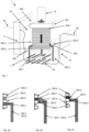
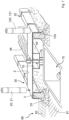
- FIG 1 shows a charging infrastructure system 1, which comprises several lines 15, 50, a base 203 arranged above the lines 15, 50 and a tubular casing body 202 arranged on an upper side of the base 203 facing away from the lines 15, 50 and connected to it.
- the lines 15, 50 are laid in a trench 22 and run along a line direction L. In the example shown, they run parallel to a head end of a parking space 95, which is formed by a curbstone 3 cast in concrete in the ground 80 (the concrete base of which is in Figure 1 not shown).
- the base 203 consists of legs 203.1, 203.2 arranged on both sides of the line 15, 50 and at least one connecting section 203.3 arranged transversely thereto and connecting the legs 203.1, 203.2, each of which has a material thickness of 2 cm. Together, these form a cavity that is open downwards and on both sides in the line direction L, into which the lines 15, 50 are accommodated when the charging infrastructure system 1 is assembled.
- the lines are designed as cable ducts 15 that extend completely through the cavity formed. Power cables 50 are shown in the cable ducts 15, one or some of which are led upwards into the casing body 202, but others (namely most of them) run through the base 203 without interruption.
- the casing body 202 itself is designed as a composite corrugated pipe, and accordingly has elevations 202.4 and depressions 202.5 on its radially outward-facing outer side 202.3, which are closed in each elevation/depression 202.4/5. and is smooth or flat on its inside.
- the connecting section 203.3 has a recess for receiving the enveloping body 202 (the former is in Figure 1 shown cut for illustration purposes); the enveloping body 202 thus projects downwards through the connecting section 203.3 into the cavity formed by the base 203 and is (as in Figure 2b shown in detail) is secured against slipping downwards in a vertical direction by a holding element 203.5 inserted into one of the recesses 202.5 of the enveloping body 202.
- the base 203 and the casing body 202 form a charging module substructure 200, on or at which a charging module 10 can be arranged.
- a mounting support 201 can also be seen, which is additionally molded onto an upper section 202.1 of the casing body 202, which is opposite the lower section 202.2, and is intended for mounting the charging module 10 thereon. This is made of polymer concrete and forms a slightly larger base area for mounting the charging module 10.
- Figures 2a, 2b and 2c show detailed views of alternative embodiments of a direct ( Figure 2a ) or an indirect ( Figures 2b and 2c ) positive connection between the connecting section 203.3 and the casing body 202.
- the connecting section 203.3 engages directly in the recess 202.5, i.e. is directly connected to it in a form-fitting manner.
- the connecting section 203.3 does not enter the recess 202.5 directly, but by means of a separate engagement element 203.4 which is attached to it, for example, by means of a screw.
- a rubber seal made of EPDM for example, inserted into the recess 202.5, A holding element 203.5 may be provided which secures the casing body 202 against slipping downwards.
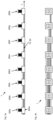
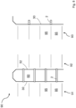
- FIGs 3a and 3b show an exemplary structure of the charging infrastructure system 1 in a side view and a top view.
- a total of eight charging module substructures 200a-200h are arranged one behind the other in the line direction L and are connected to one another via lines 15.
- a total of eight lines 15 are accommodated in its cavity, one of which ends in the first charging module substructure 200a to supply the latter, and a further seven of which run uninterruptedly through the latter to supply the charging module substructures 200b-200h located downstream of the line (see also the top view of the charging infrastructure system 1 in Figure 3b ).
- each of the eight cables 15 ends in one of the eight charging module substructures 200a-200h and each of these charging module substructures 200a-200h is connected via a separate cable 15 (in Figure 3a in line 15 and therefore not visible) is connected to a central energy transfer point.
- Figure 3a It can also be seen that several lines are arranged next to one another (ie transversely to the line direction L in the horizontal direction) as well as one above the other (ie in the vertical direction) in the cavity of the base 203. However, the upper lines 15 only run in the first to fourth charging module substructures 200a-200d; the lower lines, however, run at least as far as the fifth charging module substructure 200e.
- FIG 3b shows a top view of the Figure 3a Charging infrastructure system 1 shown, in combination with Figure 3a the advantageous arrangement of the lines 15 and their course in system 1 can be clearly seen. Due to the arrangement shown, each of the charging module substructures 200a-200h can be connected to the central energy transfer point and thus supplied with the electrical energy required for rapid charging of modern electric vehicles.
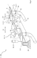
- FIG. 4 shows a charging infrastructure system 1 or charging system 100, which comprises an installation support 2, which is attached to a curb 3.
- a fastening section 2.1 of the installation support 2 is placed on the curb 3, i.e. it clamps around a front side wall 3.1 and a rear side wall 3.2 opposite in the transverse direction 13, as well as an upper side 3.3 of the curb 3.
- the installation support 2 is screwed to the curb 3, i.e. a first (front) leg 2.1.1 and a second (rear) leg 2.1.2 are screwed to the curb 3 with screws 4 passing through the curb 3.
- the installation support 2 has a mounting section 2.2, which is used to mount a Figure 1 only partially (and elsewhere) shown charging module 10, in this case a charging station 11 for electric vehicles.
- the installation support 2 is provided with holes 5, e.g. threaded holes for screwing on the charging station 11. These can be installed on site or at the factory to adapt to the charging module 10 to be installed; alternatively, threaded bolts could also be provided, for example welded on.
- the installation support 2 is also provided with a hole 6 through which an electrical or data cable laid in a cable duct 15 can be guided upwards.
- a cable protection pipe 16 forms the cable duct 15, which is connected from below to a pipe socket 2.2.1 formed on the installation support 2.
- the installation support 2 is made of metal, the rear leg 2.1.2 and the pipe socket 2.2.1 are welded on.
- a cover plate 2a of the installation support extends continuously over the fastening and assembly sections 2.1, 2.2 and in between.
- a screw bolt 7 is welded into the fastening section 2.1, over which a crash protection 20 can be attached, in this case a bollard 21. This then sits vertically above the curb 3, and is therefore anchored to the Curbstone 3 is held stable in the ground.
- a lower section of the curbstone 3 is enclosed by a concrete base 25, which also covers a lower section of the two side walls 3.1, 3.2, compare the representation in the section on the front left.
- the curbstone 3 is part of an edge edging 30, which is made up of a large number of curbs placed next to one another in a longitudinal direction 33.
- a further (second) installation support 2.2 is attached to a further (second) curbstone 3.2. Its structure and connection are analogous to the above description, so a large number of installation supports 2 and thus charging modules 10 can be attached along the edge edging 30.
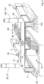
- Figure 5 shows a charging infrastructure system 1, which is largely similar to that Figure 1
- the same reference symbols designate the same parts or parts with the same function and reference is always made to the description of the other figures.
- the variant according to Figure 2 differs in the type of cable duct 15. This is used in Figure 2 formed by a cable tray 45. This is U-shaped in cross-section, the cables 50 can be inserted from above. This can simplify installation compared to pulling them through, especially when there are a large number of cables. Several installation supports 2 or charging modules can then be connected via the tray 45.
- the channel 45 is or will be closed at the top with one or more covers 46 placed one next to the other in the longitudinal direction 33, so that the channel 45 can be easily opened for subsequent use or similar.
- the installation support 2 can sit on a cover 46 and this can be drilled out in the area of the hole 6; alternatively, the installation support 2 can be placed between two covers 46.
- the installation support 2 extends to the second edge edging 32, where it is also attached to a curb 103.
- the assembly section 2.2 is located in the middle between the edge edgings 30, 32, so the charging module installed there (not shown) then supplies the parking spaces on both sides.
- a crash barrier 120 in this case a bollard 121, is also mounted on the second edge edging 32 on the installation support 2.
- the cable duct 15 leads into an access shaft 70, which can be made of concrete or built into the ground as a plastic shaft.
- the charging infrastructure system as a whole can be connected via one or more such shafts, so several cable ducts 15 can also be connected, for example.
- the variant according to Figure 7 differs from that of Figure 6 only in the sense that the cable tray 45 does not open directly into the access shaft 70, but is connected to it via a corrugated pipe 75.
- the corrugated pipe 75 is connected to the cable tray 45 from below and opens laterally into the access shaft 70.
- Figure 7 further illustrates some components of the floor 80, namely, in addition to the concrete base 25, a gravel bed 81 and an asphalt layer 82 on the parking space side.
- the area of the green strip can be filled up to a comparable height with gravel 81, above which, for example, soil for greening can fill the area between the edge borders 30, 32.
Landscapes
- Engineering & Computer Science (AREA)
- Power Engineering (AREA)
- Transportation (AREA)
- Mechanical Engineering (AREA)
- Charge And Discharge Circuits For Batteries Or The Like (AREA)
- Laying Of Electric Cables Or Lines Outside (AREA)
Applications Claiming Priority (1)
| Application Number | Priority Date | Filing Date | Title |
|---|---|---|---|
| DE102023113433.7A DE102023113433A1 (de) | 2023-05-23 | 2023-05-23 | Ladeinfrastruktursystem |
Publications (1)
| Publication Number | Publication Date |
|---|---|
| EP4475366A1 true EP4475366A1 (fr) | 2024-12-11 |
Family
ID=91193641
Family Applications (1)
| Application Number | Title | Priority Date | Filing Date |
|---|---|---|---|
| EP24177046.0A Pending EP4475366A1 (fr) | 2023-05-23 | 2024-05-21 | Système d'infrastructure de charge |
Country Status (2)
| Country | Link |
|---|---|
| EP (1) | EP4475366A1 (fr) |
| DE (1) | DE102023113433A1 (fr) |
Citations (4)
| Publication number | Priority date | Publication date | Assignee | Title |
|---|---|---|---|---|
| EP2899332A1 (fr) * | 2014-01-23 | 2015-07-29 | Hauff-Technik GmbH & Co. KG | Passage encastrable dans un élément de mur ou de sol |
| WO2021219839A1 (fr) * | 2020-04-30 | 2021-11-04 | INSTATE GmbH | Module de bordure, groupe de modules de bordure, station de charge et procédé de fonctionnement d'appareils de ce type |
| CN214874275U (zh) * | 2021-01-29 | 2021-11-26 | 青岛特来电新能源科技有限公司 | 一种快速建设型充电场站 |
| US20220228324A1 (en) * | 2021-01-19 | 2022-07-21 | Terreform ONE | Curb power source |
-
2023
- 2023-05-23 DE DE102023113433.7A patent/DE102023113433A1/de active Pending
-
2024
- 2024-05-21 EP EP24177046.0A patent/EP4475366A1/fr active Pending
Patent Citations (4)
| Publication number | Priority date | Publication date | Assignee | Title |
|---|---|---|---|---|
| EP2899332A1 (fr) * | 2014-01-23 | 2015-07-29 | Hauff-Technik GmbH & Co. KG | Passage encastrable dans un élément de mur ou de sol |
| WO2021219839A1 (fr) * | 2020-04-30 | 2021-11-04 | INSTATE GmbH | Module de bordure, groupe de modules de bordure, station de charge et procédé de fonctionnement d'appareils de ce type |
| US20220228324A1 (en) * | 2021-01-19 | 2022-07-21 | Terreform ONE | Curb power source |
| CN214874275U (zh) * | 2021-01-29 | 2021-11-26 | 青岛特来电新能源科技有限公司 | 一种快速建设型充电场站 |
Also Published As
| Publication number | Publication date |
|---|---|
| DE102023113433A1 (de) | 2024-11-28 |
Similar Documents
| Publication | Publication Date | Title |
|---|---|---|
| AT509086B1 (de) | Verfahren und vorrichtung zur einbringung eines rohres für optische kabel in einen festen verlegegrund | |
| EP0979329B2 (fr) | Treillis en fils metalliques pour la protection contre les chutes de pierres ou pour la consolidation d'une couche terrestre superficielle, et procede et dispositif pour la fabrication d'un tel treillis | |
| DE8333233U1 (de) | Entwaesserungsrinne | |
| EP0576939B1 (fr) | Elément de construction à usage multiple en plastique | |
| EP0785385B1 (fr) | Goulotte de câbles en matière plastique | |
| EP4518063A2 (fr) | Utilisation d'un passage pour couler dans un élément de sol | |
| EP4475366A1 (fr) | Système d'infrastructure de charge | |
| EP0829592B1 (fr) | Système pour réaliser des supports pour dalles de terrasses, balcons etc. | |
| DE102018217108A1 (de) | Dachkonstruktion für carports mit pv-modulen sowie ein verfahren zum montieren eines derartigen carports | |
| EP1376805B1 (fr) | Boîte de connexion sous-sol | |
| DE29920081U1 (de) | Balkon aus Metall | |
| EP2505721B1 (fr) | Chapiteau de route | |
| DE9014624U1 (de) | Wand, insbesondere Sichtschutzwand, Lärmschutzwand, Stützwand oder Böschungswand | |
| DE102007020075B3 (de) | Kabelkanalsystem | |
| EP0568051B1 (fr) | Elément de construction pour murs de soutènement destiné à être garni de végétation | |
| EP2521815B1 (fr) | Élément antibruit végétal et paroi antibruit | |
| DE102015113034A1 (de) | Rückhaltesystem, insbesondere aus Beton, und Verfahren zu dessen Herstellung | |
| WO2024188893A1 (fr) | Agencement d'installation pour un module de charge d'un véhicule électrique | |
| DE202023003042U1 (de) | Rinnenförmiges Bauteil zur Bildung eines Kabelkanals | |
| DE202010003418U1 (de) | Formteil zur Aufnahme wenigstens eines Solarmoduls | |
| DE102023209560A1 (de) | Rinnenförmiges Bauteil zur Bildung eines Kabelkanals | |
| EP3181780B1 (fr) | Goulotte d'alimentation | |
| EP1617003A2 (fr) | Planchers modulaires pour unités de fabrication | |
| DE2451520A1 (de) | Laermschutzelement | |
| DE4326306C2 (de) | Gleisüberwegplatte mit Spurrillenabdeckung |
Legal Events
| Date | Code | Title | Description |
|---|---|---|---|
| PUAI | Public reference made under article 153(3) epc to a published international application that has entered the european phase |
Free format text: ORIGINAL CODE: 0009012 |
|
| STAA | Information on the status of an ep patent application or granted ep patent |
Free format text: STATUS: THE APPLICATION HAS BEEN PUBLISHED |
|
| AK | Designated contracting states |
Kind code of ref document: A1 Designated state(s): AL AT BE BG CH CY CZ DE DK EE ES FI FR GB GR HR HU IE IS IT LI LT LU LV MC ME MK MT NL NO PL PT RO RS SE SI SK SM TR |
|
| STAA | Information on the status of an ep patent application or granted ep patent |
Free format text: STATUS: REQUEST FOR EXAMINATION WAS MADE |
|
| 17P | Request for examination filed |
Effective date: 20250604 |