EP4477252A1 - Dispositif d'entraînement et pompe à sang - Google Patents
Dispositif d'entraînement et pompe à sang Download PDFInfo
- Publication number
- EP4477252A1 EP4477252A1 EP23834567.2A EP23834567A EP4477252A1 EP 4477252 A1 EP4477252 A1 EP 4477252A1 EP 23834567 A EP23834567 A EP 23834567A EP 4477252 A1 EP4477252 A1 EP 4477252A1
- Authority
- EP
- European Patent Office
- Prior art keywords
- rotor
- rotating shaft
- shaft sleeve
- driving device
- fixedly connected
- Prior art date
- Legal status (The legal status is an assumption and is not a legal conclusion. Google has not performed a legal analysis and makes no representation as to the accuracy of the status listed.)
- Pending
Links
Images


Classifications
-
- A—HUMAN NECESSITIES
- A61—MEDICAL OR VETERINARY SCIENCE; HYGIENE
- A61M—DEVICES FOR INTRODUCING MEDIA INTO, OR ONTO, THE BODY; DEVICES FOR TRANSDUCING BODY MEDIA OR FOR TAKING MEDIA FROM THE BODY; DEVICES FOR PRODUCING OR ENDING SLEEP OR STUPOR
- A61M60/00—Blood pumps; Devices for mechanical circulatory actuation; Balloon pumps for circulatory assistance
- A61M60/10—Location thereof with respect to the patient's body
- A61M60/122—Implantable pumps or pumping devices, i.e. the blood being pumped inside the patient's body
- A61M60/126—Implantable pumps or pumping devices, i.e. the blood being pumped inside the patient's body implantable via, into, inside, in line, branching on, or around a blood vessel
- A61M60/13—Implantable pumps or pumping devices, i.e. the blood being pumped inside the patient's body implantable via, into, inside, in line, branching on, or around a blood vessel by means of a catheter allowing explantation, e.g. catheter pumps temporarily introduced via the vascular system
-
- A—HUMAN NECESSITIES
- A61—MEDICAL OR VETERINARY SCIENCE; HYGIENE
- A61M—DEVICES FOR INTRODUCING MEDIA INTO, OR ONTO, THE BODY; DEVICES FOR TRANSDUCING BODY MEDIA OR FOR TAKING MEDIA FROM THE BODY; DEVICES FOR PRODUCING OR ENDING SLEEP OR STUPOR
- A61M60/00—Blood pumps; Devices for mechanical circulatory actuation; Balloon pumps for circulatory assistance
- A61M60/10—Location thereof with respect to the patient's body
- A61M60/122—Implantable pumps or pumping devices, i.e. the blood being pumped inside the patient's body
- A61M60/126—Implantable pumps or pumping devices, i.e. the blood being pumped inside the patient's body implantable via, into, inside, in line, branching on, or around a blood vessel
- A61M60/135—Implantable pumps or pumping devices, i.e. the blood being pumped inside the patient's body implantable via, into, inside, in line, branching on, or around a blood vessel inside a blood vessel, e.g. using grafting
- A61M60/139—Implantable pumps or pumping devices, i.e. the blood being pumped inside the patient's body implantable via, into, inside, in line, branching on, or around a blood vessel inside a blood vessel, e.g. using grafting inside the aorta, e.g. intra-aortic balloon pumps
-
- A—HUMAN NECESSITIES
- A61—MEDICAL OR VETERINARY SCIENCE; HYGIENE
- A61M—DEVICES FOR INTRODUCING MEDIA INTO, OR ONTO, THE BODY; DEVICES FOR TRANSDUCING BODY MEDIA OR FOR TAKING MEDIA FROM THE BODY; DEVICES FOR PRODUCING OR ENDING SLEEP OR STUPOR
- A61M60/00—Blood pumps; Devices for mechanical circulatory actuation; Balloon pumps for circulatory assistance
- A61M60/20—Type thereof
- A61M60/205—Non-positive displacement blood pumps
- A61M60/216—Non-positive displacement blood pumps including a rotating member acting on the blood, e.g. impeller
- A61M60/221—Non-positive displacement blood pumps including a rotating member acting on the blood, e.g. impeller the blood flow through the rotating member having both radial and axial components, e.g. mixed flow pumps
-
- A—HUMAN NECESSITIES
- A61—MEDICAL OR VETERINARY SCIENCE; HYGIENE
- A61M—DEVICES FOR INTRODUCING MEDIA INTO, OR ONTO, THE BODY; DEVICES FOR TRANSDUCING BODY MEDIA OR FOR TAKING MEDIA FROM THE BODY; DEVICES FOR PRODUCING OR ENDING SLEEP OR STUPOR
- A61M60/00—Blood pumps; Devices for mechanical circulatory actuation; Balloon pumps for circulatory assistance
- A61M60/40—Details relating to driving
- A61M60/403—Details relating to driving for non-positive displacement blood pumps
- A61M60/408—Details relating to driving for non-positive displacement blood pumps the force acting on the blood contacting member being mechanical, e.g. transmitted by a shaft or cable
- A61M60/411—Details relating to driving for non-positive displacement blood pumps the force acting on the blood contacting member being mechanical, e.g. transmitted by a shaft or cable generated by an electromotor
- A61M60/416—Details relating to driving for non-positive displacement blood pumps the force acting on the blood contacting member being mechanical, e.g. transmitted by a shaft or cable generated by an electromotor transmitted directly by the motor rotor drive shaft
-
- A—HUMAN NECESSITIES
- A61—MEDICAL OR VETERINARY SCIENCE; HYGIENE
- A61M—DEVICES FOR INTRODUCING MEDIA INTO, OR ONTO, THE BODY; DEVICES FOR TRANSDUCING BODY MEDIA OR FOR TAKING MEDIA FROM THE BODY; DEVICES FOR PRODUCING OR ENDING SLEEP OR STUPOR
- A61M60/00—Blood pumps; Devices for mechanical circulatory actuation; Balloon pumps for circulatory assistance
- A61M60/80—Constructional details other than related to driving
- A61M60/802—Constructional details other than related to driving of non-positive displacement blood pumps
- A61M60/81—Pump housings
-
- A—HUMAN NECESSITIES
- A61—MEDICAL OR VETERINARY SCIENCE; HYGIENE
- A61M—DEVICES FOR INTRODUCING MEDIA INTO, OR ONTO, THE BODY; DEVICES FOR TRANSDUCING BODY MEDIA OR FOR TAKING MEDIA FROM THE BODY; DEVICES FOR PRODUCING OR ENDING SLEEP OR STUPOR
- A61M60/00—Blood pumps; Devices for mechanical circulatory actuation; Balloon pumps for circulatory assistance
- A61M60/80—Constructional details other than related to driving
- A61M60/802—Constructional details other than related to driving of non-positive displacement blood pumps
- A61M60/818—Bearings
- A61M60/825—Contact bearings, e.g. ball-and-cup or pivot bearings
-
- A—HUMAN NECESSITIES
- A61—MEDICAL OR VETERINARY SCIENCE; HYGIENE
- A61M—DEVICES FOR INTRODUCING MEDIA INTO, OR ONTO, THE BODY; DEVICES FOR TRANSDUCING BODY MEDIA OR FOR TAKING MEDIA FROM THE BODY; DEVICES FOR PRODUCING OR ENDING SLEEP OR STUPOR
- A61M60/00—Blood pumps; Devices for mechanical circulatory actuation; Balloon pumps for circulatory assistance
- A61M60/80—Constructional details other than related to driving
- A61M60/802—Constructional details other than related to driving of non-positive displacement blood pumps
- A61M60/827—Sealings between moving parts
- A61M60/829—Sealings between moving parts having a purge fluid supply
-
- A—HUMAN NECESSITIES
- A61—MEDICAL OR VETERINARY SCIENCE; HYGIENE
- A61M—DEVICES FOR INTRODUCING MEDIA INTO, OR ONTO, THE BODY; DEVICES FOR TRANSDUCING BODY MEDIA OR FOR TAKING MEDIA FROM THE BODY; DEVICES FOR PRODUCING OR ENDING SLEEP OR STUPOR
- A61M60/00—Blood pumps; Devices for mechanical circulatory actuation; Balloon pumps for circulatory assistance
- A61M60/80—Constructional details other than related to driving
- A61M60/855—Constructional details other than related to driving of implantable pumps or pumping devices
- A61M60/857—Implantable blood tubes
-
- Y—GENERAL TAGGING OF NEW TECHNOLOGICAL DEVELOPMENTS; GENERAL TAGGING OF CROSS-SECTIONAL TECHNOLOGIES SPANNING OVER SEVERAL SECTIONS OF THE IPC; TECHNICAL SUBJECTS COVERED BY FORMER USPC CROSS-REFERENCE ART COLLECTIONS [XRACs] AND DIGESTS
- Y02—TECHNOLOGIES OR APPLICATIONS FOR MITIGATION OR ADAPTATION AGAINST CLIMATE CHANGE
- Y02E—REDUCTION OF GREENHOUSE GAS [GHG] EMISSIONS, RELATED TO ENERGY GENERATION, TRANSMISSION OR DISTRIBUTION
- Y02E60/00—Enabling technologies; Technologies with a potential or indirect contribution to GHG emissions mitigation
- Y02E60/16—Mechanical energy storage, e.g. flywheels or pressurised fluids
Definitions
- the present application relates to the technical field of medical devices, and in particular to a driving device and a blood pump.
- Blood pump is designed to be inserted percutaneously into a patient's blood vessel, such as an artery or a vein in a thigh or an axilla, and can be advanced into the patient's heart to function as a left ventricular assist device or a right ventricular assist device.
- a patient's blood vessel such as an artery or a vein in a thigh or an axilla
- the blood pump generally includes a driving device and an impeller, and the impeller is connected to a driving shaft of the driving device.
- the impeller is connected to a driving shaft of the driving device.
- it is usually necessary to add a component for limiting the driving shaft, which makes the structure of the driving device complicated and increases the difficulty of assembling the driving device.
- the present application provides a driving device and a blood pump which are easy to assemble.
- An embodiment of a first aspect of the present application provides a driving device, including:
- An embodiment of a second aspect of the present application provides a blood pump, which includes an impeller and the driving device as described in the first aspect.
- the rotating shaft is connected to the impeller, and the rotating shaft is capable of driving the impeller to rotate.
- first and second are used for descriptive purposes only, which cannot be construed as indicating or implying a relative importance, or implicitly specifying the number of the indicated technical features.
- the features defined with “first” and “second” may explicitly or implicitly include one or more features.
- a plurality of' means two or more, unless specifically stated otherwise.
- an end of a device adjacent to an operator is usually defined as a proximal end, and an end of the device away from the operator is defined as a distal end.
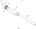
- a blood pump 1 and a driving device 10 according to an embodiment of the present application are now described.
- the blood pump 1 includes a driving device 10 and an impeller 20.
- the driving device 10 is in transmission connection with the impeller 20, and the driving device 10 is capable of driving the impeller 20 to rotate.
- the blood pump 1 further includes a cannula 40 secured to a distal end of the driving device 10.
- the impeller 20 is rotatably accommodated in the cannula 40.
- the cannula 40 has a blood inlet 41 and a blood outlet 42. When the impeller 20 rotates, blood flows from the blood inlet 41 into the cannula 40 and then flows out of the blood outlet 42.
- the cannula 40 extends through a heart valve, such as an aortic valve.
- the blood inlet 41 is located within a heart, and the blood outlet 42 and the driving device 10 are located in a blood vessel, such as an aorta outside a heart.
- the blood pump 1 further includes a catheter 50 connected to a proximal end of the driving device 10.
- the catheter 50 is configured to accommodate various supply lines.
- the supply lines include a wire configured to be electrically connected to the driving device 10 and a cleaning pipeline configured to supply flushing fluid to the blood pump 1.
- the flushing fluid is physiological saline, physiological saline containing heparin, or glucose, etc.
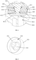
- the driving device 10 includes a housing 100, a rotating shaft 200, a first rotor 300, a first shaft sleeve 400, a second shaft sleeve 500, and a limiting member 600.
- the housing 100 is substantially a cylindrical housing with openings at both ends thereof. A distal end of the housing 100 is secured to the cannula 40, and a proximal end of the housing 100 is secured to the catheter 50.
- the housing 100 has an inner cavity. Specifically, a separating ring 110 is provided in the housing 100, and the separating ring 110 divides the inner cavity of the housing 100 into a limiting cavity 102 and an accommodating cavity 103. In the illustrated embodiment, the limiting cavity 102 and the accommodating cavity 103 are arranged along an axial direction of the housing 100.
- the rotating shaft 200 is elongated.
- the rotating shaft 200 is rotatably mounted to the housing 100, and the rotating shaft 200 is configured to be connected to the impeller 20.
- the rotating shaft 200 extends substantially along the axial direction of the housing 100, in other words, an axis of the rotating shaft 200 extends in a direction substantially consistent with the axial direction of the housing 100. Therefore, the limiting cavity 102 and the accommodating cavity 103 are arranged substantially along the axis of the rotating shaft 200.
- the rotating shaft 200 extends through the limiting cavity 102, is partially accommodated in the accommodating cavity 103, and is partially located outside the housing 100 or extends partially into the cannula 40.
- an end of the rotating shaft 200 configured to be connected to the impeller 20 is a connecting end 210.
- the rotating shaft 200 is made of a ceramic material. Compared with metal materials, ceramics have higher processing precision, higher biocompatibility and mechanical strength, and better wear resistance and corrosion resistance.
- the first rotor 300 is fixedly connected to an end of the rotating shaft 200. Specifically, the first rotor 300 is fixedly connected to an end of the rotating shaft 200 away from the connecting end 210.
- the first rotor 300 has a spherical head portion 310 that protrudes along the axis of the rotating shaft 200 in a direction away from the connecting end 210.
- the first rotor 300 is located in the housing 100.
- the first rotor 300 is located in the accommodating cavity 103. The first rotor 300 can rotate relative to the housing 100 and can drive the rotating shaft 200 to rotate.
- the driving device 10 further includes a stator 700 capable of driving the first rotor 300 to rotate.
- the stator 700 is fixedly mounted in the housing 100, the stator 700 is specifically located in the accommodating cavity 103, and the rotating shaft 200 rotatably extends through the stator 700.
- the first rotor 300 is magnetic, and the stator 700 is capable of generating a rotating magnetic field that drives the first rotor 300 to rotate.
- the first rotor 300 includes a first flywheel 320 fixedly connected to the rotating shaft 200 and a first magnet 330 fixedly connected to the first flywheel 320.
- the first magnet 330 and the first flywheel 320 cooperatively constitute a rotor body of the first rotor 300.
- the first magnet 330 is an annular Halbach array magnet.
- the spherical head portion 310 is provided on the first flywheel 320.
- the first flywheel 320 includes a first disc-shaped portion 321, a first inner tube 322, and a first outer tube 323.
- Both the first inner tube 322 and the first outer tube 323 are of circular tubular structures, and the first disc-shaped portion 321 is of an annular disc structure. Ends of the first inner tube 322 and the first outer tube 323 are fixedly connected to the first disc-shaped portion 321.
- the first inner tube 322 and the first outer tube 323 are located on the same side of the first disc-shaped portion 321 and are coaxially arranged.
- An inner diameter of the first outer tube 323 is greater than an outer diameter of the first inner tube 322.
- the first inner tube 322 is at least partially accommodated in the first outer tube 323.
- a first annular cavity 324 accommodating the first magnet 330 is formed between the first outer tube 323 and the first inner tube 322.
- a shape of the first annular cavity 324 is adapted to a shape of the first magnet 330, so as to facilitate mounting and positioning the first magnet 330.
- Such arrangement enables the first flywheel 320 to limit the first magnet 330, which not only facilitates the mounting of the first magnet 330, but also enables the first magnet 330 and the first flywheel 320 to be combined more stably.
- the end of the rotating shaft 200 away from the connecting end 210 is fixedly accommodated in the first inner tube 322, that is, the rotating shaft 200 does not extend through the first disc-shaped portion 321, so that the driving device 10 can be designed to be shorter.
- the spherical head portion 310 is located on a side of the first disc-shaped portion 321 away from the first inner tube 322.
- the first rotor 300 further includes a connecting column portion 340 having one end fixedly connected to the rotor body, and the spherical head portion 310 is formed at an end of the connecting column portion 340 away from the rotor body.
- the end of the connecting pillar portion 340 away from the spherical head portion 310 is fixedly connected to the first flywheel 320 (specifically, the first disc-shaped portion 321).
- An axis of the connecting column portion 340 coincides with the axis of the rotating shaft 200.
- the spherical head portion 310 is substantially hemispherical.
- the spherical head portion 310 has a spherical crown surface 311 and a circular bottom surface connected to the spherical crown surface 311.
- the circular bottom surface is connected to an end surface of the connecting column portion 340.
- the connecting column portion 340 is coaxial with the spherical head portion 310, and a diameter of an end surface of the connecting column portion 340 adjacent to the spherical head portion 310 is equal to a diameter of the circular bottom surface.
- the first flywheel 320 is not limited to the above structure. In some embodiments, the first flywheel 320 does not have the first outer tube 323. In some embodiments, the first flywheel 320 does not have the first outer tube 323 and the first inner tube 322. In this case, the rotating shaft 200 fixedly extends through a center of the first disc-shaped portion 321. Compared to the first flywheel 320 having only the first disc-shaped portion 321, the first inner tube 322 enables the first flywheel 320 to be more stably connected to the rotating shaft 200.
- both the first shaft sleeve 400 and the second shaft sleeve 500 are mounted to the housing 100.
- the first shaft sleeve 400 is accommodated in the accommodating cavity 103
- the second shaft sleeve 500 is accommodated in the limiting cavity 102.
- Both the first shaft sleeve 400 and the second shaft sleeve 500 are fixedly connected to the housing 100.
- the first shaft sleeve 400 and the second shaft sleeve 500 are spaced apart from each other along the axial direction of the housing 100.
- the rotating shaft 200 rotatably extends through the second shaft sleeve 500, and the second shaft sleeve 500 is provided closer to the connecting end 210 of the rotating shaft 200 than the first shaft sleeve 400.
- the first rotor 300 is located between the first shaft sleeve 400 and the second shaft sleeve 500.
- the stator 700 is also located between the first shaft sleeve 400 and the second shaft sleeve 500.
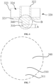
- the first shaft sleeve 400 is provided with a groove 410 having a concave spherical groove wall 412.
- the spherical head portion 310 of the first rotor 300 is movably provided in the groove 410, and the spherical head portion 310 can abut against the spherical groove wall 412.
- the groove 410 can support and limit the spherical head portion 310 of the first rotor 300, so as to limit a movement range of the first rotor 300 and the rotating shaft 200 along the axis of the rotating shaft 200 in a direction away from the impeller 20, and at the same time, to limit a swinging range of the rotating shaft 200 in a radial direction of the rotating shaft 200.
- the connecting column portion 340 is partially accommodated in the groove 410.
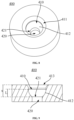
- the groove 410 has a notch 413, and the connecting column portion 340 extends through the notch 413.
- a length h of the spherical head portion 310 in an axial direction of the rotating shaft 200 is less than a depth s of the groove 410 (the depth s of the groove 410 is the maximum distance between the notch 413 of the groove 410 and the spherical groove wall 412), so as to better limit the spherical head portion 310 in the groove 410, and reduce radial swing ranges of the first rotor 300 and the rotating shaft 200.
- a radius of the spherical groove wall 412 is greater than a radius of the spherical head portion 310, i.e., a radius of a sphere in which the spherical groove wall 412 is located is greater than a radius of a sphere in which the spherical head portion 310 is located.
- a length L of the spherical groove wall 412 in an axial direction of the first shaft sleeve 400 is less than the depth s of the groove 410.
- the notch 413 of the groove 410 is rounded, i.e., a groove wall at the notch 413 of the groove 410 is rounded, so as to prevent the connecting column portion 340 from being scratched and worn by the notch 413 of the groove 410 with the angular notch 413 of the groove 410.
- the spherical head portion 310 is provided with a diamond coating to make its surface smooth and improve wear resistance.
- the first shaft sleeve 400 is further provided with a liquid feeding hole 420 in communication with the groove 410.
- the liquid feeding hole 420 can be in fluid communication with the cleaning pipeline in the catheter 50, so that the flushing liquid can enter the groove 410 through the liquid feeding hole 420.
- the flushing liquid enters between the groove wall of the groove 410 and the spherical head portion 310 to serve as a lubricant, so as to reduce the friction between the spherical head portion 310 and the groove wall of the groove 410, thereby reducing the wear of the spherical head portion 310 and the first shaft sleeve 400.
- an opening 421 of the liquid feeding hole 420 is located at a center of the spherical groove wall 412, so that the flushing fluid entering the groove 410 from the liquid feeding hole 420 can provide an axial impact force to the spherical head portion 310 as much as possible. More specifically, a central axis of the liquid feeding hole 420 coincides with a central axis of a cavity enclosed by the spherical groove wall 412, so that the liquid feeding hole 420 is a straight hole to reduce the energy consumption of the flushing liquid in the liquid feeding hole 420.
- a diameter of the opening 421 of the liquid feeding hole 420 located on the spherical groove wall 412 is 1/9 to 1/3 of a diameter of a sphere where the spherical head portion 310 is located.
- the diameter of the liquid feeding hole 420 is constant, that is, the diameter of the liquid feeding hole 420 is 1/9 to 1/3 of the diameter of the sphere where the spherical head portion 310 is located.
- the diameter of the opening 421 of the liquid feeding hole 420 on the spherical groove wall 412 is too large, a contact surface between the spherical head portion 310 and the spherical groove wall 412 will be reduced (resulting in a larger pressure per unit area), and the wear of the spherical head portion 310 by the spherical groove wall 412 will be increased. If the diameter of the opening 421 is too small, the amount of the flushing liquid entering the groove 410 from the liquid feeding hole 420 will be affected.
- the flushing liquid entering the groove 410 provides the spherical head portion 310 with the impact force, and at the same time, the flushing liquid enters between the spherical head portion 310 and the spherical groove wall 412 to serve as a lubricant, so as to reduce a friction coefficient between the spherical head portion 310 and the spherical groove wall 412. Therefore, the amount of the flushing liquid entering the groove 410 should not be too small.
- the driving device 10 further includes a fixing base 810 fixedly connected to the housing 100.
- the fixing base 810 is provided with a mounting cavity 811 and a liquid inlet hole 812 in communication with the mounting cavity 811.
- the first shaft sleeve 400 is mounted in the mounting cavity 811.
- the liquid feeding hole 420 is in communication with the liquid inlet hole 812.
- An end of the liquid inlet hole 812 away from the mounting cavity 811 is configured to be in communication with the cleaning pipeline of the catheter 50, so that the flushing liquid can flow between the groove wall of the groove 410 and the spherical head portion 310 through the liquid inlet hole 812 and the liquid feeding hole 420, and then flow into the inner cavity of the housing 100.
- the mounting cavity 811 has a cavity bottom 8111, and an opening 8121 (see FIG. 4 ) of the liquid inlet hole 812 is located at the cavity bottom 8111 of the mounting cavity 811.
- a supporting step 8112 is provided in the mounting cavity 811, and the supporting step 8112 abuts against the first shaft sleeve 400, so that the first shaft sleeve 400 is spaced from the cavity bottom 8111 by a certain distance, so as to better ensure the smooth circulation of the flushing liquid.
- the supporting step 8112 abuts against a surface of the first shaft sleeve 400 away from the second shaft sleeve 500.
- the fixing base 810 is further provided with a branch channel 813, and the branch channel 813 is in fluid communication with the liquid inlet hole 812, so that fluid (such as flushing liquid) flowing through the liquid inlet hole 812 can also flow into the housing 100 through the branch channel 813.
- one end of the branch channel 813 is in communication with a gap between the first shaft sleeve 400 and the cavity bottom 8111 of the mounting cavity 811, and the other end of the branch channel 813 is in communication with the accommodating cavity 103.
- the branch channel 813 is formed by partially recessing a cavity wall of the mounting cavity 811.
- the flushing liquid in a normal state, is divided into two streams after entering the mounting cavity 811 from the liquid inlet hole 812, one stream flows into the groove 410 of the first shaft sleeve 400 through the liquid feeding hole 420, and the other stream flows out through the branch channel 813.
- the branch channel 813 can ensure the flow of the flushing liquid when the spherical head portion 310 blocks the liquid feeding hole 420.
- branch channels 813 are provided, and the two branch channels 813 are arranged opposite to each other. It should be understood that the number of the branch channel 813 can be adjusted according to design requirements, for example, in some embodiments, one or more than two branch channels 813 are provided.
- the second shaft sleeve 500 abuts against the separating ring 110.
- the second shaft sleeve 500 is accommodated in the limiting cavity 102, and the second shaft sleeve 500 can be conveniently positioned by the separating ring 110, so that the assembly of the second shaft sleeve 500 can be facilitated.
- the second shaft sleeve 500 is provided with a shaft hole 510, and the rotating shaft 200 rotatably extends through the shaft hole 510.
- a central axis of the shaft hole 510 coincides with the central axis of the liquid feeding hole 420 of the first shaft sleeve 400.
- a gap is provided between a hole wall of the shaft hole 510 of the second shaft sleeve 500 and the rotating shaft 200 for the fluid to flow through.
- the flushing liquid entering the accommodating cavity 103 can flow out of the housing 100 through the gap between the rotating shaft 200 and the hole wall of the shaft hole 510.
- the limiting member 600 is fixedly connected to the rotating shaft 200, the limiting member 600 is located between the second shaft sleeve 500 and the first rotor 300, and the limiting member 600 can abut against the second shaft sleeve 500, so as to limit a moving range of the rotating shaft 200 along the axis of the rotating shaft 200 in a direction approaching the second shaft sleeve 500.
- the stator 700 is located between the first rotor 300 and the stop member 600.
- the limiting member 600 includes a pushing stop ring 610 and a second rotor 620.
- the second rotor 620 is fixedly connected to the rotating shaft 200
- the pushing stop ring 610 is fixedly connected to at least one of the second rotor 620 and the rotating shaft 200.
- the pushing stop ring 610 may be directly fixed only to the second rotor 620, may be directly fixed only to the rotating shaft 200, or may be directly fixed to both the second rotor 620 and the rotating shaft 200.
- the pushing stop ring 610 is fixedly connected to the rotating shaft 200, and the pushing stop ring 610 is fixedly connected to at least one of the second rotor 620 and the rotating shaft 200, the pushing stop ring 610, the rotating shaft 200, and the second rotor 620 can rotate and move synchronously.
- the pushing stop ring 610 is located between the second rotor 620 and the second shaft sleeve 500, and the pushing stop ring 610 can abut against the second shaft sleeve 500 to limit the movement range of the rotating shaft 200 along the axial direction of the rotating shaft 200 in a direction approaching the impeller 20.
- the first rotor 300 is fixedly connected to one end of the rotating shaft 200, and the spherical head portion 310 of the first rotor 300 is provided in the groove 410 of the first shaft sleeve 400 and can abut against the spherical groove wall 412 of the groove 410, so as to limit the moving range of the rotating shaft 200 along the axis of the rotating shaft 200 in the direction away from the impeller 20, thereby limiting a position of the rotating shaft 200 on the axis of the rotating shaft 200.
- the groove wall of the groove 410 of the first shaft sleeve 400 can also limit the swinging range of the spherical head portion 310 in the radial direction of the rotating shaft 200, thereby achieving the overall limitation of the swinging range of the rotating shaft 200 in the radial direction.
- the above design not only achieves an axial limit to the rotating shaft 200, but also achieves a radial limit to the rotating shaft 200.
- the second rotor 620 is accommodated in the accommodating cavity 103, and the separating ring 110 is located between the second rotor 620 and the second shaft sleeve 500.
- the second rotor 620 includes a second flywheel 621 fixedly connected to the rotating shaft 200 and a second magnet 622 fixed to the second flywheel 621.
- the connection strength between the second magnet 622 and the rotating shaft 200 can be enhanced.
- the shaking of the rotating shaft 200 during rotation can be reduced, so that the whole rotating shaft 200 is more stable during rotation.
- the second magnet 622 is an annular Halbach array magnet.
- the second flywheel 621 includes a second disc-shaped portion 6211, a second inner tube 6212, and a second outer tube 6213.
- the second inner tube 6212 and the second outer tube 6213 are both of circular tubular structures, and the second disc-shaped portion 6211 is of an annular disc structure. Both the second inner tube 6212 and the second outer tube 6213 are fixedly connected to the second disc-shaped portion 6211.
- the second outer tube 6213 surrounds the second disc-shaped portion 6211, the second inner tube 6212 and the second outer tube 6213 are arranged coaxially, and the rotating shaft 200 extends through the second inner tube 6212 and is fixedly connected to the second inner tube 6212.
- a second annular cavity is formed between the second inner tube 6212 and the second outer tube 6213.
- the second magnet 622 is accommodated in the second annular cavity.
- a shape of the second annular cavity is adapted to the second magnet 622, so as to facilitate mounting and positioning the second magnet 622.
- Such arrangement enables the second flywheel 621 to limit the second magnet 622, which not only facilitates the mounting of the second magnet 622, but also enables the second magnet 622 and the second flywheel 621 to be combined more stably.
- the second flywheel 621 is not limited to the above structure. In some embodiments, the second flywheel 621 does not have the second outer tube 6213. In some embodiments, the second flywheel 621 does not have the second inner tube 6212 and the second outer tube 6213, and at this time, the rotating shaft 200 fixedly extends through a center of the second disc-shaped portion 6211. Compared to the second flywheel 621 having only the second disc-shaped portion 6211, the second inner tube 6212 enables the second flywheel 621 to be more stably connected to the rotating shaft 200.
- the pushing stop ring 610 is an annular protrusion formed on a side of the second flywheel 621 away from the stator 700, and more specifically, the pushing stop ring 610 is provided on a side of the second disc-shaped portion 6211 away from the second inner tube 6212. That is, the pushing stop ring 610 and the second flywheel 621 are integrally formed as a whole. Since the overall volume of the blood pump 1 is small, the volume of the pushing stop ring 610 is smaller, it is difficult to be processed in precision, and has large assembly difficulty, the pushing stop ring 610 and the second flywheel 621 are integrally formed to facilitate the mounting, and the adhering operation is omitted.
- the pushing stop ring 610 and the second rotor 620 may also be of separate structures prior to assembly.
- the pushing stop ring 610 may be secured to at least one of the second rotor 620 and the rotating shaft 200 by adhering or welding.
- the pushing stop ring 610 when the pushing stop ring 610 abuts against the second shaft sleeve 500, the pushing stop ring 610 is at least partially located in an inner ring of the separating ring 110, a gap for fluid to flow is provided between the pushing stop ring 610 and a wall of the inner ring of the separating ring 110, and the separating ring 110 is spaced apart from the second rotor 620 by a certain distance.
- the flushing liquid can flow into the shaft hole 510 of the second shaft sleeve 500 through the gap between the pushing stop ring 610 and the wall of the inner ring of the separating ring 110, that is, the fluid communication between the shaft hole 510 of the second shaft sleeve 500 and the accommodating cavity 103 is achieved.
- the separating ring 110 is spaced apart from the second rotor 620 by the certain distance, so as to avoid wear due to the friction between the second rotor 620 and the separating ring 110 when the pushing stop ring 610 abuts against the second shaft sleeve 500.
- the pushing stop ring 610 is substantially ring-shaped, and a central axis of the pushing stop ring 610 coincides with the axis of the rotating shaft 200.
- An outer diameter of the pushing stop ring 610 is less than an inner diameter of the separating ring 110, so that there is the gap for fluid to flow between the pushing stop ring 610 and the wall of the inner ring of the separating ring 110.
- the pushing stop ring 610 may also be formed by arranging a plurality of sector rings that are evenly spaced around the rotating shaft 200 for one circumference, or may be understood as being formed by arranging a plurality of sector rings that are circumferentially discretely arranged.
- a thickness of the pushing stop ring 610 along the axis of the rotating shaft 200 is greater than a thickness of the separating ring 110 along the axis of the rotating shaft 200, so that the separating ring 110 is spaced apart from the second rotor 620 by a certain distance when the pushing stop ring 610 abuts against the second shaft sleeve 500. It should be understood that, in some embodiments, the thickness of the pushing stop ring 610 along the axis of the rotating shaft 200 can be less than or equal to the thickness of the separating ring 110 along the axis of the rotating shaft 200.
- the second rotor 620 and the pushing stop ring 610 may be spaced apart by a certain distance along the axis of the rotating shaft 200, and the distance is sufficient to ensure that the separating ring 110 and the second rotor 620 are spaced apart by a certain distance when the pushing stop ring 610 abuts against the second shaft sleeve 500.
- a surface of the second shaft sleeve 500 facing the pushing stop ring 610 is partially recessed to form a guiding groove 530, and the guiding groove 530 is in communication with the shaft hole 510 of the second shaft sleeve 500.
- the guiding groove 530 is formed by partially recessing the surface of the second shaft sleeve 500 facing the pushing stop ring 610, so that the flushing fluid can flow better between the pushing stop ring 610 and the second shaft sleeve 500 to lubricate the contact surface between the pushing stop ring 610 and the second shaft sleeve 500 and reduce the friction between the pushing stop ring 610 and the second shaft sleeve 500.
- the wear problem due to the friction between the pushing stop ring 610 and the second shaft sleeve 500 is reduced, and the heat dissipation effect on the pushing stop ring 610 and the second shaft sleeve 500 is achieved.
- the pushing stop ring 610 has a blocking surface 611 perpendicular to the axis of the rotating shaft 200.
- the second shaft sleeve 500 has a stopping surface 520 perpendicular to the central axis of the shaft hole 510 of the second shaft sleeve 500.
- the stopping surface 520 is opposite to the blocking surface 611, and the stopping surface 520 can abut against the blocking surface 611, so as to limit the movement of the rotating shaft 200 along the axis of the rotating shaft 200 in a direction approaching the impeller 20.
- the rotating shaft 200 rotatably extends through the shaft hole 510 of the second shaft sleeve 500, so that when the rotating shaft 200 operates normally and the pushing stop ring 610 abuts against the second shaft sleeve 500, the blocking surface 611 and the stopping surface 520 can be in contact with each other, which can reduce the wear caused by the friction between the pushing stop ring 610 and the second shaft sleeve 500.
- the stopping surface 520 abuts against the separating ring 110.
- the guiding groove 530 is formed by partially recessing the stopping surface 520
- a roughness of at least one of the blocking surface 611 and the stopping surface 520 is less than or equal to 0.1 microns. In some embodiments, the roughness of both the blocking surface 611 and the stopping surface 520 is less than or equal to 0.1 microns. In some embodiments, the roughness of one of the blocking surface 611 and the stopping surface 520 is less than or equal to 0.1 microns.
- At least one of the blocking surface 611 and the stopping surface 520 is a ceramic surface. Ceramic has high machining accuracy, high biocompatibility, high mechanical strength, good wear resistance and corrosion resistance.
- the pushing stop ring 610 and the second shaft sleeve 500 may be made of ceramic, or at least one of the blocking surface 611 and the stopping surface 520 may be a ceramic surface by providing a ceramic coating.
- the blocking surface 611 is made of diamond, so that the blocking surface 611 has a relatively high hardness, a relatively smooth surface, and is wear-resistant.
- the material of the blocking surface 611 is a ceramic surface by providing a diamond coating.
- the stator 700 includes a first stator unit 710 and a second stator unit 720 arranged along the axis of the rotating shaft 200.
- the first stator unit 710 is capable of driving the first rotor 300 to rotate
- the second stator unit 720 is capable of driving the second rotor 620 to rotate.
- the first stator unit 710 can generate a rotating magnetic field to drive the first rotor 300 to rotate
- the second stator unit 720 can generate a rotating magnetic field to drive the second rotor 620 to rotate.
- Both the first stator unit 710 and the second stator unit 720 are fixedly accommodated in the accommodating cavity 103 of the housing 100.
- the rotating shaft 200 rotatably extends through the first stator unit 710 and the second stator unit 720.
- the first stator unit 710 and the second stator unit 720 are both located between the first rotor 300 and the second rotor 620.
- the first rotor 300, the second rotor 620, the first stator unit 710, and the second stator unit 720 are located between the first shaft sleeve 400 and the second shaft sleeve 500.
- the first rotor 300 is adjacent to the first shaft sleeve 400
- the second rotor 620 is adjacent to the second shaft sleeve 500.
- first shaft sleeve 400, the first rotor 300, the first stator unit 710, the second stator unit 720, the second rotor 620, and the second shaft sleeve 500 are arranged sequentially along the axis of the rotating shaft 200, and the second shaft sleeve 500 is located closest to the connecting end 210 of the rotating shaft 200.
- the first stator unit 710 and the second stator unit 720 each includes a magnetic core and a coil wound around the magnetic core.
- the first stator unit 710 includes a first magnetic core 711 and a first coil 712 wound around the first magnetic core 711.
- a plurality of first magnetic cores 711 are provided, and the plurality of first magnetic cores 711 are arranged around the axis of the rotating shaft 200 for one circumference.
- Each first magnetic core 711 corresponds to one first coil 712.
- the structure of the second stator unit 720 is similar to that of the first stator unit 710.
- the second stator unit 720 includes a second magnetic core 721 and a second coil 722 wound around the second magnetic core 721.
- a plurality of second magnetic cores 721 are provided, and the plurality of second magnetic cores 721 are arranged around the axis of the rotating shaft 200 for one circumference.
- Each second magnetic core 721 corresponds to one second coil 722.
- the driving device 10 further includes a magnetic conduction member 820 fixedly connected to the housing 100.
- Both the first magnetic core 711 of the first stator unit 710 and the second magnetic core 721 of the second stator unit 720 are fixedly connected to the magnetic conduction member 820.
- the magnetic conduction member 820 is fixedly accommodated in the housing 100, e.g., snapped into an inner side wall of the housing 100.
- the rotating shaft 200 rotatably extends through the magnetic conduction member 820.
- One end of the first magnetic core 711 is fixedly connected to the magnetic conduction member 820, and the first rotor 300 is adjacent to the other end of the first magnetic core 711.
- One end of the second magnetic core 721 is fixedly connected to the magnetic conduction member 820, and the second rotor 620 is adjacent to the other end of the second magnetic core 721.
- the magnetic conduction member 820 serves to close a magnetic circuit, so as to promote and increase generation of the magnetic flux and improve a coupling capability. Therefore, the magnetic conduction member 820 can function to close the magnetic circuit between the first stator unit 710 and the first rotor 300, and to close the magnetic circuit between the second stator unit 720 and the second rotor 620, so as to increase the magnetic flux. Therefore, the arrangement of the magnetic conduction member 820 helps to reduce an overall diameter of the driving device 10.
- both the first magnetic core 711 of the first stator unit 710 and the second magnetic core 721 of the second stator unit 720 are fixedly connected to the magnetic conduction member 820, so that the first stator unit 710 and the second stator unit 720 can be positioned and mounted, and the assembly difficulty of the first stator unit 710 and the second stator unit 720 is reduced.
- the magnetic conduction member 820 provided in the above manner can also reduce arrangement of a positioning structure in the housing 100, thereby simplifying the structure of the housing 100 and simplifying the assembly process of the entire driving device 10.
- the magnetic conduction member 820 includes two magnetic conduction plates 821 that are stacked.
- One magnetic conduction plate 821 is fixedly connected to the first magnetic core 711 of the first stator unit 710, and the other magnetic conduction plate 821 is fixedly connected to the second magnetic core 721 of the second stator unit 720.
- the rotating shaft 200 rotatably extends through the two magnetic conduction plates 821. Specifically, the two magnetic conduction plates 821 are separated prior to assembly.
- the magnetic conduction member 820 is configured as the two magnetic conduction plates 821 that are separated prior to assembly, when assembling the driving device 10, the first magnetic core 711 can be first fixedly connected to the magnetic conduction plate 821, the second magnetic core 721 can be fixedly connected to the other magnetic conduction plate 821, and then the two magnetic conduction plates 821 can be stacked. In this way, the first magnetic core 711 and the second magnetic core 721 can be easily assembled to the two magnetic conduction plates 821, respectively, and the first magnetic core 711 and the second magnetic core 721 can be assembled more easily.
- the two magnetic conduction plates 821 are fixedly connected, so that the first stator unit 710, the second stator unit 720, and the magnetic conduction member 820 are integrally formed and assembled into the housing 100, and the assembly of the stator 700 is easier.
- the two magnetic conduction plates 821 may be connected together by gluing or welding. It should be understood that in other embodiments, the two magnetic conduction plates 821 are not fixedly connected, but are in contact with each other.
- the magnetic conduction member 820 is not limited to the combination of the two magnetic conduction plates 821 that are separated, and the magnetic conduction member 820 may be a plate-like structure. Both the first magnetic core 711 and the second magnetic core 721 are connected to the magnetic conduction member 820, that is, the first stator unit 710 and the second stator unit 720 share one magnetic conduction member 820.
- the magnetic conduction plate 821 is made of silicon steel, and the first magnetic core 711 and the second magnetic core 721 are made of silicon steel.
- the first magnetic core 711 and the second magnetic core 721 each has a columnar structure without a head portion (i.e., a pole shoe) having a large width.
- the magnetic core of the columnar structure can reduce the magnetic loss and increase the magnetic coupling density between the magnetic core and the magnet to increase the torque of the stator 700 to the magnet (under the same current conditions).
- the magnetic core without the head portion can also greatly reduce the problems of local magnetic short circuit and motor power reduction caused by the contact between adjacent magnetic cores.
- the structure of the driving device 10 is not limited to the above structure.
- the driving device 10 includes the first rotor 300, the second rotor 620, and the stator 700, but the stator 700 has only one stator unit, i.e., only the first stator unit 710, without the second stator unit 720.
- the first stator unit 710 is located between the first rotor 300 and the second rotor 620, and the first stator unit 710 is capable of simultaneously driving the first rotor 300 and the second rotor 620 to rotate.
- the limiting member 600 is not limited to the above structure.
- the limiting member 600 only has the pushing stop ring 610 without the second rotor 620.
- the stator 700 only has one stator unit.
- the pushing stop ring 610 is fixedly connected to the rotating shaft 200 and abuts against the second shaft sleeve 500, so as to limit the movement range of the rotating shaft 200 along the axis thereof in a direction approaching the second shaft sleeve 500.
- the limiting member 600 is only the second rotor 620 without the pushing stop ring 610.
- the second rotor 620 is fixedly connected to the rotating shaft 200, the stator 700 is located between the first rotor 300 and the second rotor 620, and a side of the second rotor 620 away from the stator 700 abuts against the second shaft sleeve 500 or the separating ring 110, so as to limit the movement range of the rotating shaft 200 along the axis thereof in a direction approaching the impeller 20.
- the driving device of this embodiment has a structure similar to that of the driving device of the first embodiment, the driving device of this embodiment and the blood pump having the driving device of this embodiment also have effects similar to those of the first embodiment.
Landscapes
- Health & Medical Sciences (AREA)
- Heart & Thoracic Surgery (AREA)
- Engineering & Computer Science (AREA)
- Life Sciences & Earth Sciences (AREA)
- General Health & Medical Sciences (AREA)
- Anesthesiology (AREA)
- Biomedical Technology (AREA)
- Hematology (AREA)
- Cardiology (AREA)
- Animal Behavior & Ethology (AREA)
- Mechanical Engineering (AREA)
- Public Health (AREA)
- Veterinary Medicine (AREA)
- Vascular Medicine (AREA)
- Transplantation (AREA)
- Structures Of Non-Positive Displacement Pumps (AREA)
- External Artificial Organs (AREA)
Applications Claiming Priority (2)
| Application Number | Priority Date | Filing Date | Title |
|---|---|---|---|
| CN202210801382.2A CN115282470B (zh) | 2022-07-08 | 2022-07-08 | 驱动装置和血泵 |
| PCT/CN2023/098354 WO2024007793A1 (fr) | 2022-07-08 | 2023-06-05 | Dispositif d'entraînement et pompe à sang |
Publications (2)
| Publication Number | Publication Date |
|---|---|
| EP4477252A1 true EP4477252A1 (fr) | 2024-12-18 |
| EP4477252A4 EP4477252A4 (fr) | 2025-10-15 |
Family
ID=83822728
Family Applications (1)
| Application Number | Title | Priority Date | Filing Date |
|---|---|---|---|
| EP23834567.2A Pending EP4477252A4 (fr) | 2022-07-08 | 2023-06-05 | Dispositif d'entraînement et pompe à sang |
Country Status (4)
| Country | Link |
|---|---|
| EP (1) | EP4477252A4 (fr) |
| JP (1) | JP2025504248A (fr) |
| CN (2) | CN115282470B (fr) |
| WO (1) | WO2024007793A1 (fr) |
Cited By (1)
| Publication number | Priority date | Publication date | Assignee | Title |
|---|---|---|---|---|
| CN120919516A (zh) * | 2025-10-16 | 2025-11-11 | 成都华心永动医疗科技有限公司 | 介入式血压辅助加压系统 |
Families Citing this family (2)
| Publication number | Priority date | Publication date | Assignee | Title |
|---|---|---|---|---|
| CN115282470B (zh) * | 2022-07-08 | 2023-08-18 | 深圳核心医疗科技股份有限公司 | 驱动装置和血泵 |
| CN116407753B (zh) * | 2022-12-09 | 2024-10-01 | 深圳核心医疗科技股份有限公司 | 驱动机构和血泵 |
Family Cites Families (27)
| Publication number | Priority date | Publication date | Assignee | Title |
|---|---|---|---|---|
| DE4321260C1 (de) * | 1993-06-25 | 1995-03-09 | Westphal Dieter Dipl Ing Dipl | Blutpumpe als Zentrifugalpumpe |
| US20060089521A1 (en) * | 2004-10-21 | 2006-04-27 | Chang Sheldon S L | Rotor driven linear flow blood pump |
| US8419609B2 (en) * | 2005-10-05 | 2013-04-16 | Heartware Inc. | Impeller for a rotary ventricular assist device |
| DE102012202411B4 (de) * | 2012-02-16 | 2018-07-05 | Abiomed Europe Gmbh | Intravasale blutpumpe |
| EP2719403B1 (fr) * | 2012-10-12 | 2016-09-28 | Abiomed Europe GmbH | Pompe sanguine centrifuge |
| US9144638B2 (en) * | 2013-03-14 | 2015-09-29 | Thoratec Corporation | Blood pump rotor bearings |
| CN103438000B (zh) * | 2013-07-24 | 2016-01-13 | 张翼 | 圆柱定轨转子泵及圆柱定轨转子泵组合增压内燃发动机 |
| CN103362829A (zh) * | 2013-08-03 | 2013-10-23 | 浙江威格泵业有限公司 | 一种屏蔽泵 |
| KR101457816B1 (ko) * | 2013-10-04 | 2014-11-03 | 지엠비코리아 주식회사 | 전동식 워터 펌프 |
| CN105221234A (zh) * | 2015-09-18 | 2016-01-06 | 河南省西峡汽车水泵股份有限公司 | 一种高稳定隔离式的电动水泵 |
| EP3300749A1 (fr) * | 2016-09-29 | 2018-04-04 | Berlin Heart GmbH | Pompe à sang magnétisée passivement |
| EP3205360B1 (fr) * | 2016-02-11 | 2018-08-29 | Abiomed Europe GmbH | Pompe sanguine |
| AU2018250273B2 (en) * | 2017-04-05 | 2023-06-08 | Bivacor Inc. | Heart pump drive and bearing |
| CN111770765B (zh) * | 2018-01-08 | 2024-05-14 | 星辰Bp有限公司 | 心脏辅助装置 |
| US10722627B1 (en) * | 2018-05-24 | 2020-07-28 | RBTS Inc. | Blood pump bearing with integrated fluid diffuser/inducer system |
| EP3574932A1 (fr) * | 2018-05-28 | 2019-12-04 | Berlin Heart GmbH | Pompe à sang |
| CN110768441B (zh) * | 2018-07-25 | 2024-12-31 | 广东威灵汽车部件有限公司 | 水泵及车辆 |
| US11565103B2 (en) * | 2018-10-18 | 2023-01-31 | Boston Scientific Scimed, Inc. | Blood pump shaft bearing |
| CN111375098B (zh) * | 2018-12-29 | 2023-04-07 | 上海微创心力医疗科技有限公司 | 经皮血泵及其转子限位结构 |
| EP3698820A1 (fr) * | 2019-02-22 | 2020-08-26 | ECP Entwicklungsgesellschaft mbH | Dispositif de cathéter avec un couvercle d'arbre d'entraînement |
| FR3095018B1 (fr) * | 2019-04-10 | 2022-12-02 | Fineheart | Pompe cardiaque à couplage magnétique et à flux inverse. |
| CN112472999B (zh) * | 2020-12-22 | 2025-03-21 | 深圳核心医疗科技股份有限公司 | 血泵 |
| CN114652952B (zh) * | 2020-12-23 | 2025-08-19 | 上海微创心力医疗科技有限公司 | 用于血泵的轴承、血泵以及心室辅助循环装置 |
| CN113730795A (zh) * | 2021-10-08 | 2021-12-03 | 卡迪美科(北京)生物科技有限公司 | 医用离心泵 |
| CN216456526U (zh) * | 2021-11-17 | 2022-05-10 | 上海微创心力医疗科技有限公司 | 介入式血管血泵 |
| CN115282470B (zh) * | 2022-07-08 | 2023-08-18 | 深圳核心医疗科技股份有限公司 | 驱动装置和血泵 |
| CN117797396A (zh) * | 2022-08-15 | 2024-04-02 | 深圳核心医疗科技股份有限公司 | 驱动装置和血泵 |
-
2022
- 2022-07-08 CN CN202210801382.2A patent/CN115282470B/zh active Active
- 2022-07-08 CN CN202310913352.5A patent/CN116808430A/zh active Pending
-
2023
- 2023-06-05 WO PCT/CN2023/098354 patent/WO2024007793A1/fr not_active Ceased
- 2023-06-05 JP JP2024547673A patent/JP2025504248A/ja active Pending
- 2023-06-05 EP EP23834567.2A patent/EP4477252A4/fr active Pending
Cited By (1)
| Publication number | Priority date | Publication date | Assignee | Title |
|---|---|---|---|---|
| CN120919516A (zh) * | 2025-10-16 | 2025-11-11 | 成都华心永动医疗科技有限公司 | 介入式血压辅助加压系统 |
Also Published As
| Publication number | Publication date |
|---|---|
| JP2025504248A (ja) | 2025-02-06 |
| CN115282470A (zh) | 2022-11-04 |
| CN116808430A (zh) | 2023-09-29 |
| WO2024007793A1 (fr) | 2024-01-11 |
| EP4477252A4 (fr) | 2025-10-15 |
| CN115282470B (zh) | 2023-08-18 |
Similar Documents
| Publication | Publication Date | Title |
|---|---|---|
| EP4477252A1 (fr) | Dispositif d'entraînement et pompe à sang | |
| CN115414591B (zh) | 驱动装置和血泵 | |
| EP4520388A1 (fr) | Appareil d'entraînement et pompe à sang | |
| EP4299103A1 (fr) | Pompe à sang et son dispositif d'entraînement | |
| EP4552683A1 (fr) | Dispositif d'entraînement et pompe à sang | |
| US20250367428A1 (en) | Driving mechanism and blood pump | |
| US20250195868A1 (en) | Driving mechanism and blood pump | |
| US12521544B2 (en) | Driving apparatus and blood pump | |
| CN115282467B (zh) | 驱动机构和血泵 | |
| EP4563186A1 (fr) | Appareil d'entraînement et pompe d'assistance circulatoire | |
| EP4393537A1 (fr) | Appareil d'entraînement et pompe d'assistance circulatoire | |
| CN119139609B (zh) | 驱动机构和血泵 | |
| CN115364366B (zh) | 驱动机构和血泵 | |
| CN115192894B (zh) | 驱动装置及血泵 | |
| CN115382092A (zh) | 驱动装置和血泵 |
Legal Events
| Date | Code | Title | Description |
|---|---|---|---|
| STAA | Information on the status of an ep patent application or granted ep patent |
Free format text: STATUS: THE INTERNATIONAL PUBLICATION HAS BEEN MADE |
|
| PUAI | Public reference made under article 153(3) epc to a published international application that has entered the european phase |
Free format text: ORIGINAL CODE: 0009012 |
|
| STAA | Information on the status of an ep patent application or granted ep patent |
Free format text: STATUS: REQUEST FOR EXAMINATION WAS MADE |
|
| 17P | Request for examination filed |
Effective date: 20240909 |
|
| AK | Designated contracting states |
Kind code of ref document: A1 Designated state(s): AL AT BE BG CH CY CZ DE DK EE ES FI FR GB GR HR HU IE IS IT LI LT LU LV MC ME MK MT NL NO PL PT RO RS SE SI SK SM TR |
|
| REG | Reference to a national code |
Ref country code: DE Ref legal event code: R079 Free format text: PREVIOUS MAIN CLASS: A61M0060810000 Ipc: A61M0060130000 |
|
| A4 | Supplementary search report drawn up and despatched |
Effective date: 20250911 |
|
| DAV | Request for validation of the european patent (deleted) | ||
| DAX | Request for extension of the european patent (deleted) | ||
| RIC1 | Information provided on ipc code assigned before grant |
Ipc: A61M 60/13 20210101AFI20250905BHEP Ipc: A61M 60/221 20210101ALI20250905BHEP Ipc: A61M 60/416 20210101ALI20250905BHEP Ipc: A61M 60/81 20210101ALI20250905BHEP Ipc: A61M 60/825 20210101ALI20250905BHEP Ipc: A61M 60/829 20210101ALI20250905BHEP |