EP4477324A2 - Dispositif pour appliquer un adhésif à un ou plusieurs composants sur un mélange granulaire, et procédé pour sa mise en oeuvre - Google Patents
Dispositif pour appliquer un adhésif à un ou plusieurs composants sur un mélange granulaire, et procédé pour sa mise en oeuvre Download PDFInfo
- Publication number
- EP4477324A2 EP4477324A2 EP24203462.7A EP24203462A EP4477324A2 EP 4477324 A2 EP4477324 A2 EP 4477324A2 EP 24203462 A EP24203462 A EP 24203462A EP 4477324 A2 EP4477324 A2 EP 4477324A2
- Authority
- EP
- European Patent Office
- Prior art keywords
- rail
- trolley
- adhesive
- carriage
- spray
- Prior art date
- Legal status (The legal status is an assumption and is not a legal conclusion. Google has not performed a legal analysis and makes no representation as to the accuracy of the status listed.)
- Pending
Links
Images


Classifications
-
- B—PERFORMING OPERATIONS; TRANSPORTING
- B05—SPRAYING OR ATOMISING IN GENERAL; APPLYING FLUENT MATERIALS TO SURFACES, IN GENERAL
- B05B—SPRAYING APPARATUS; ATOMISING APPARATUS; NOZZLES
- B05B12/00—Arrangements for controlling delivery; Arrangements for controlling the spray area
- B05B12/08—Arrangements for controlling delivery; Arrangements for controlling the spray area responsive to condition of liquid or other fluent material to be discharged, of ambient medium or of target ; responsive to condition of spray devices or of supply means, e.g. pipes, pumps or their drive means
- B05B12/12—Arrangements for controlling delivery; Arrangements for controlling the spray area responsive to condition of liquid or other fluent material to be discharged, of ambient medium or of target ; responsive to condition of spray devices or of supply means, e.g. pipes, pumps or their drive means responsive to conditions of ambient medium or target, e.g. humidity, temperature position or movement of the target relative to the spray apparatus
- B05B12/126—Arrangements for controlling delivery; Arrangements for controlling the spray area responsive to condition of liquid or other fluent material to be discharged, of ambient medium or of target ; responsive to condition of spray devices or of supply means, e.g. pipes, pumps or their drive means responsive to conditions of ambient medium or target, e.g. humidity, temperature position or movement of the target relative to the spray apparatus responsive to target velocity, e.g. to relative velocity between spray apparatus and target
-
- B—PERFORMING OPERATIONS; TRANSPORTING
- B05—SPRAYING OR ATOMISING IN GENERAL; APPLYING FLUENT MATERIALS TO SURFACES, IN GENERAL
- B05B—SPRAYING APPARATUS; ATOMISING APPARATUS; NOZZLES
- B05B12/00—Arrangements for controlling delivery; Arrangements for controlling the spray area
- B05B12/14—Arrangements for controlling delivery; Arrangements for controlling the spray area for supplying a selected one of a plurality of liquids or other fluent materials or several in selected proportions to a spray apparatus, e.g. to a single spray outlet
- B05B12/1418—Arrangements for controlling delivery; Arrangements for controlling the spray area for supplying a selected one of a plurality of liquids or other fluent materials or several in selected proportions to a spray apparatus, e.g. to a single spray outlet for supplying several liquids or other fluent materials in selected proportions to a single spray outlet
-
- B—PERFORMING OPERATIONS; TRANSPORTING
- B05—SPRAYING OR ATOMISING IN GENERAL; APPLYING FLUENT MATERIALS TO SURFACES, IN GENERAL
- B05B—SPRAYING APPARATUS; ATOMISING APPARATUS; NOZZLES
- B05B13/00—Machines or plants for applying liquids or other fluent materials to surfaces of objects or other work by spraying, not covered by groups B05B1/00 - B05B11/00
- B05B13/005—Machines or plants for applying liquids or other fluent materials to surfaces of objects or other work by spraying, not covered by groups B05B1/00 - B05B11/00 mounted on vehicles or designed to apply a liquid on a very large surface, e.g. on the road, on the surface of large containers
-
- B—PERFORMING OPERATIONS; TRANSPORTING
- B05—SPRAYING OR ATOMISING IN GENERAL; APPLYING FLUENT MATERIALS TO SURFACES, IN GENERAL
- B05B—SPRAYING APPARATUS; ATOMISING APPARATUS; NOZZLES
- B05B13/00—Machines or plants for applying liquids or other fluent materials to surfaces of objects or other work by spraying, not covered by groups B05B1/00 - B05B11/00
- B05B13/02—Means for supporting work; Arrangement or mounting of spray heads; Adaptation or arrangement of means for feeding work
- B05B13/04—Means for supporting work; Arrangement or mounting of spray heads; Adaptation or arrangement of means for feeding work the spray heads being moved during spraying operation
- B05B13/0421—Means for supporting work; Arrangement or mounting of spray heads; Adaptation or arrangement of means for feeding work the spray heads being moved during spraying operation with rotating spray heads
-
- B—PERFORMING OPERATIONS; TRANSPORTING
- B61—RAILWAYS
- B61D—BODY DETAILS OR KINDS OF RAILWAY VEHICLES
- B61D15/00—Other railway vehicles, e.g. scaffold cars; Adaptations of vehicles for use on railways
-
- E—FIXED CONSTRUCTIONS
- E01—CONSTRUCTION OF ROADS, RAILWAYS, OR BRIDGES
- E01B—PERMANENT WAY; PERMANENT-WAY TOOLS; MACHINES FOR MAKING RAILWAYS OF ALL KINDS
- E01B1/00—Ballastway; Other means for supporting the sleepers or the track; Drainage of the ballastway
- E01B1/001—Track with ballast
-
- E—FIXED CONSTRUCTIONS
- E01—CONSTRUCTION OF ROADS, RAILWAYS, OR BRIDGES
- E01B—PERMANENT WAY; PERMANENT-WAY TOOLS; MACHINES FOR MAKING RAILWAYS OF ALL KINDS
- E01B27/00—Placing, renewing, working, cleaning, or taking-up the ballast, with or without concurrent work on the track; Devices therefor; Packing sleepers
-
- E—FIXED CONSTRUCTIONS
- E01—CONSTRUCTION OF ROADS, RAILWAYS, OR BRIDGES
- E01B—PERMANENT WAY; PERMANENT-WAY TOOLS; MACHINES FOR MAKING RAILWAYS OF ALL KINDS
- E01B37/00—Making, maintaining, renewing, or taking-up the ballastway or the track, not provided for in a single one of groups E01B27/00 - E01B35/00
-
- B—PERFORMING OPERATIONS; TRANSPORTING
- B05—SPRAYING OR ATOMISING IN GENERAL; APPLYING FLUENT MATERIALS TO SURFACES, IN GENERAL
- B05B—SPRAYING APPARATUS; ATOMISING APPARATUS; NOZZLES
- B05B15/00—Details of spraying plant or spraying apparatus not otherwise provided for; Accessories
- B05B15/60—Arrangements for mounting, supporting or holding spraying apparatus
- B05B15/68—Arrangements for adjusting the position of spray heads
-
- E—FIXED CONSTRUCTIONS
- E01—CONSTRUCTION OF ROADS, RAILWAYS, OR BRIDGES
- E01B—PERMANENT WAY; PERMANENT-WAY TOOLS; MACHINES FOR MAKING RAILWAYS OF ALL KINDS
- E01B2204/00—Characteristics of the track and its foundations
- E01B2204/03—Injecting, mixing or spraying additives into or onto ballast or underground
Definitions
- the invention relates to a device for applying one-component or multi-component adhesive to a granular mixture, in particular for applying one-component or multi-component adhesive to the ballast of a rail line.
- the two fluid components are fed from storage tanks via two separate feed lines using gear pumps in precisely controllable flow rates via a mixer unit, thereby producing a fluid sprayable adhesive mixture.
- a spray unit with at least one spray nozzle or with a spray bar with several discharge nozzles is used to specifically discharge the adhesive mixture onto the ballast bed.
- one-component adhesives can also be used and conveyed with such a device, with exactly the same structural features of the device.
- the invention also relates to a method for using this device and its use for applying adhesives, both two-component and one-component, to the ballast of a rail line.
- ballasted superstructure In long-distance traffic, the ballasted superstructure is the dominant base layer. In urban local traffic, on bridges or in tunnels, however, a solid road surface is used. Adhesive systems offer an efficient solution for both types of construction and for connecting different road surfaces. In the ballasted superstructure as a route, the loosely laid track grid made of rails and sleepers lies in this unbound, compacted ballast bed without any lateral fastening.
- the ballast bed can absorb considerable compressive forces, but can only be moved within limits under tensile loads.
- Adhesive systems ensure positional stability quickly and permanently in difficult areas such as rail joints or switches.
- special measures are necessary to secure the position of the ballast bed. Bonding the ballast shoulders with one-component adhesives or, even better, with two-component resin-hardener mixtures has proven to be an effective method for this.
- the use of a fast-curing adhesive system saves a great deal of time and money.
- a particularly difficult area for rail tracks is the integration of different types of construction. Transitions between a ballasted superstructure and a solid track are problematic due to the different settlement behavior.
- the gradual bonding of the ballast has proven to be an effective measure for equalizing different elasticities.
- Adhesive systems also offer particular advantages here, namely short waiting times until the load is able to bear the load and the adhesive system's very good environmental compatibility.
- inner-city local transport it is mainly solid tracks and grass tracks that determine the appearance of rail tracks.
- the two-component mixtures offer efficient detailed solutions for stabilizing, sealing and designing the track systems.
- Two-component mixtures can be adapted to the respective situation by varying the mixing ratio of resin and hardener during the curing time and achieve better bonding quality than single-component adhesives, which involve a certain compromise.
- single-component adhesives are easier to handle because no mixer is required and only a single pump and pipe are needed for delivery.
- Devices for the controlled pumping, dosing, mixing and dispensing of such adhesives, whether single- or two-component adhesives, using gear pumps, among other things, are also known in principle.
- Bonding ballast in track construction has various positive effects. Among other things, it enables the tracks to be stabilized and joints to be reduced at transitions from the ballasted track to the fixed track, for example at tunnel entrances and exits.
- the ballast is usually bonded over the entire surface, including under the rails and sleepers. In order to reduce joints at the transitions between the ballasted track and the fixed track, the penetration depth of the bonding is gradually increased towards the fixed track. Bonding the ballast can not only improve driving comfort, but also the longevity of the tracks, as it prevents the stones from shifting.
- Bonding the ballast bed in the edge area of a rail line is often of crucial importance if a trench is to be dug near the rail line, or if material is to be excavated next to the rail line as a result of a construction project, such as the laying of another parallel rail line or a building, a retaining wall, etc. or for other construction measures.
- a construction project such as the laying of another parallel rail line or a building, a retaining wall, etc. or for other construction measures.
- a channel several meters wide and, for example, 0.5 to 2 meters deep is dug out of the ground, on the bottom of which vehicles such as trucks, dumpers, excavators and other machines can then travel. new railway line.
- This shoulder proves to be advantageous when laying and maintaining control and signal cables along the tracks, as a trench can be easily dug outside the bonded area and the laid control and signal cables can be easily exposed thanks to the defined, stable shoulder of the ballast bed and the trench can be filled in again after the cables have been replaced without affecting the basic shape of the ballast bed.
- the ballast bed shoulder stabilized by bonding can still be used with the usual loads despite the trench being dug directly next to the rail line. With a professionally bonded ballast line, it can be cut off to the side and, for example, excavation can be carried out directly next to the ballast bed. Thanks to the bonding, the necessary stability of the ballast line for normal train travel is maintained, which offers enormous advantages.
- the rail line can also be reinforced across its entire width using ballast bonding using the same device.
- the application of the adhesives to create such a stable bond requires that the penetration depth of the adhesive into the ballast bed reaches a precisely specified depth everywhere and that the amount of adhesive is applied at a precisely constant rate with a defined spray width per linear meter, whereby multi-component adhesives must always be applied in the correct mixing ratio of the composite adhesive. Furthermore, such a Bonding can be carried out quickly and reliably over larger sections, not just over a few meters. All of the necessary boundary conditions must be adhered to with extreme precision.
- the application of adhesives can be carried out very professionally, as shown in the document WO 2018/010860 A1, published on 18 January 2018 is comprehensively presented.
- the device shown there allows the adhesives to be applied in a dosage that sprays a very specific amount of adhesive onto the ballast bed per linear meter, thus ensuring a certain pre-calculated penetration depth.
- the process carried out using this device is now even certified by the Swiss Federal Railways SBB, which means that its use guarantees that the rail bed will subsequently offer a certain desired load-bearing capacity and can therefore be used as usual by trains weighing several hundred tonnes.
- the application is inevitably interrupted in order to refill a watering can or to move the supplies, i.e. the containers and machinery for pumping the adhesive to the lance, forward in stages, as these containers and equipment are either carried on a railway wagon or transported by road and set up alongside the track section. If for any reason a malfunction occurs, for example a pump does not work correctly or breaks down, a single component that is toxic in itself can be sprayed in large quantities, which can have fatal consequences for the groundwater.
- the components of multi-component adhesives may only be applied when thoroughly mixed in the prescribed mixing ratio. Then the mixture hardens reliably and no individual component can enter the soil in isolation.
- Bonding must always be carried out quickly and determines the penetration depth, because the adhesive runs down through the gravel and as it bonds and hardens quickly, the penetration depth is limited.
- the work on applying the adhesive has so far usually had to be carried out outside of traffic times and often at night, and dry weather is also a prerequisite for Applying the adhesive. It is clear that there are many boundary conditions and this results in the requirement that a uniform application with precisely defined specifications should be carried out reliably by machine and very quickly on site.
- bonding is to take place somewhere on a section of rail, for example in a station, or in places that are difficult to access such as bridges, underpasses or overpasses, or generally in places where the side of the rail cannot be accessed by vehicles, it is particularly challenging to be able to apply the adhesive evenly and quickly, if possible in no time at all, i.e. without any interruptions.
- a particular challenge for the rapid and controlled application of adhesive - with a perfect mixture of components in the case of a multi-component adhesive - and with a consistent penetration depth over long distances in an instant is the fact that large quantities are required for the necessary machinery and storage containers. For example, powerful pumps are required. In addition, an independent energy supply is required, both for the pumps and, depending on the situation, for tempering the adhesive to be applied or its components, which must be available in large quantities. And then all of these devices should be able to be moved along a route. It is a good idea to transport these devices along a rail line in a truck, but this cannot be driven along the track so evenly that the right amount of adhesive per linear meter could be reliably applied with a spray boom attached to it. Or a railway carriage could carry the adhesives and the equipment for tempering, mixing and pumping them separately, but the uniform application of the adhesives could be carried directly from a railway carriage is difficult to realize because it has no drive and has a large dead mass.
- the object of the present invention is to create a device and a method which can be used even more quickly and flexibly, so that ballast bonding along a rail line can be carried out, depending on the situation, without blocking the rail line in question, i.e. that the time periods between the passing of trains can be used and regular train traffic can continue without disruption.
- This complete device can be transported by road or brought to the location on the track.
- the vehicle with the entire device for providing and pumping the adhesive or the adhesive components for the adhesive mixture travels essentially parallel to the track, independently of the train traffic or in such a way that regular train traffic is not hindered.
- a trolley or a light rail car is placed on the rails within a very short time, approximately within seconds.
- This trolley or this rail car carries a boom with at least one spray nozzle.
- the trolley or this light rail car can travel on the rail with an electrical drive at a selectable uniform speed, whereby the boom mounted or molded onto the trolley or the rail car with a at least one spray nozzle moves along the rail at exactly the same uniform speed.
- the trolley or this lightweight rail carriage can be quickly placed on a rail and put into operation within a few seconds and just as quickly removed from the rail to clear the way for a train.
- the rail trolley or rail carriage is preferably controlled by remote control.
- the travel speeds and the GPS coordinates can also be recorded or transmitted and saved live in a cloud.
- this trolley or light rail car can be supplied by a railway car travelling on a parallel track or the same track instead of a truck travelling alongside the track, which is then gradually pulled or pushed along by a light locomotive or handcar using the spraying device.
- the trolley or light rail car is then the only thing that ensures the adhesive is applied evenly; a defined amount of adhesive is applied precisely depending on the speed of movement of the nozzles, thus ensuring a precisely defined depth of penetration.
- a separate light rail car or trolley moves forward evenly on the rail as a spray car, or the spray nozzles can be moved back and forth evenly on this rail car or spray car, so that a predefined depth of penetration is ultimately maintained.
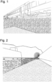
- FIG. 1 A bonded ballast bed layer is shown, namely a ballast line cut just outside along a rail line, which was previously bonded by spraying on a two-component synthetic resin so that it forms a quasi-monolithic block.
- the ballast line to be mined can be cut off with an excavator bucket, as shown here, and the bonded ballast shoulder remains stable, so that vertical walls can be exposed without the drivable ballast line losing any significant load-bearing capacity and stability.
- cables or pipes have to be laid along such a rail line
- major challenges arise for maintaining the stability of the rail line if it is to continue to be used by trains, i.e. during the installation work for the cables and pipes.
- the rail line would have to be closed to rail traffic, which would mean major restrictions and expensive downtime for the rail operators.
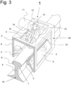
- the Figure 2 shows another ballast track stabilized by bonding and then cut off along a track in front of a tunnel portal.
- a trench often has to be dug over considerable distances, and here the particular problem is how to stabilize a ballast track over longer distances so reliably and safely that it can be certified for use by trains with normal loads.
- it is removed by hand, no one can guarantee the homogeneity of the bond.
- bonding by hand is much too slow, requires a lot of personnel, is inaccurate and accordingly expensive.
- ballast tracks to be bonded in a completely different dimension, much faster and more efficiently, and completely homogeneously, with a precisely consistent, selectable width of the bond and with a precisely definable penetration depth of the adhesive over the entire bond. Only such a mechanical application of the adhesive can be carried out with such precision that the bonding and stabilization can be certified, so that a railway operator can be sure that trains can travel on this bonded route without any problems and are also allowed to do so from an insurance perspective.
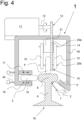
- the Figure 3 shows a rail-mounted trolley 1 of the device according to the invention for placing on a single rail and for applying adhesive to an area next to the rail. It is seen here in perspective from an angle seen from above and placed on a single rail 16, thus in the rail-coupled or rail-bound state.
- the trolley 1 forms a frame 40 or box, inside of which wheels 2, 3, 4 are mounted.
- two wheels 2 are arranged on the frame 40 or box so that they are directed towards the corner 7 between the rail head 8 and the rail web 9.
- the wheels 2 are mounted on a bevel 5 on one side of the frame 40.
- At least one guide wheel 3 projects at right angles to the vertical frame part 6 towards the rail web 9 and rolls on it on this other side or flank of the rail head 8.
- two guide wheels 3 are arranged opposite the wheels 2 on this side of the rail head 8.
- At least one drivable wheel 4 presses onto the rail head 8 from above in the frame 40.
- the wheel 4 can be pivotally connected to the frame 40, for example by being mounted between two pivot arms 10 as shown here, which in turn can be pivoted about a horizontal axis on the frame 40 and press downwards under spring load, thereby pressing the wheel 4 onto the top of the rail head 8 when the trolley 1 is attached.
- An electric motor 11 is arranged on top of the frame 40 of the trolley 1, the output shaft 12 of which drives a gear ring 13 for a roller chain 14 or a gear for a toothed belt.
- the roller chain 14 or the toothed belt then drives an associated gear ring 15 or a gear next to the wheel 4, which is firmly connected to the same.
- This makes it possible to firstly push the trolley 1 upwards by the bearing force of the drive wheel 4, against the holding force of the two guide wheels 2, while at least one outer guide wheel 3 runs on the side of the rail head 8 and, together with the guide wheels 2, secures the trolley 1 against swiveling in any direction.
- this trolley 1 is designed with two such guide wheels 3 for rolling on the side of the rail head 8. Its only degree of freedom of movement is the displacement in the direction of the rail 16 on which its wheels 2-4 roll. With an electronic control of the electric motor 11, it is possible to ensure a selectable uniform movement of this trolley 1 on a rail 16.
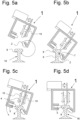
- the Figure 4 shows this trolley 1 of the device according to the invention in a front view and mounted on a single rail 16.
- the wheels 2 point into the corner 7 between the rail head 8 and the rail web 9. They are attached to the edge 5 of the frame 40, with this edge 5 facing inwards and at an oblique angle upwards and the wheels 2 attached here to the edge 5 below.
- this guide wheel 3 which acts as a support wheel
- the two ears 17, 18 are adjustable here using the adjusting screws 42, as indicated by the double arrows, so that the guide wheel 3 can be adapted to any varying track head widths.
- At least one further wheel acts from above, which serves as a drive wheel 4 and which rests and rolls on the top of the rail head 8 under spring load. In the example shown, it is held on the axis 20b between two pivot arms 10 attached to the frame 40, which are pivotally connected to an attachment 21 on the horizontal axis 20. On one side of the wheel 4, this is equipped with a gear ring 15 or a gear wheel.
- a roller chain 14 runs over this gear ring 15, which runs above over another gear ring 13, which in turn is driven by the output shaft 12 of the electric motor 11.
- a toothed belt or a gear transmission can be used to transfer the power of the electric motor 11 to the drive wheel 4.
- this trolley 1 that is to say its frame 40 or its housing, can be placed on or lifted off a rail 16 very quickly. From the position shown here it can be lifted away from the rail 16 and removed by lifting it on the left side and then unhooking the two wheels 2 by moving the edge 5 or the frame 40 downwards and outwards. Conversely, the trolley 1 with its guide wheels 2 can be quickly hooked onto the rail 16 and brought into position.
- the two wheels 2 are brought into position with the frame 40 at an angle to the rail 16 and then the frame 40 is pivoted down anti-clockwise in the image shown until the drive wheel 4 rests on the top of the rail head 8.
- the wheel 3 then rests on the other side of the rail head 8 and the trolley 1 is guided stably along the rail.
- All described wheels can be adapted in position, type and shape to different rail profile types.
- the number of wheels 2, 3, 4 can also vary as long as they can fulfill the function described.
- one or more crawlers can be used in addition to or instead of the wheels 2, 3, 4, whereby the trolley 1 can be driven safely along the rail track 9.
- the trolley 1 is pivoted about its longitudinal axis, as shown in Figure 5c shown and indicated with an arrow until the drive wheel 4 rests on the top of the rail head 8 and is then pressed onto the rail head 8 by the force of the spring acting on its swivel arms 10.
- the guide wheel 3 or - depending on the design - the guide wheels 3 - rests snugly on the side of the rail head 8 and the trolley 1 is held securely against rotation in every direction and snugly on the rail 16, as in Figure 5d shown.
- the trolley 1 can now only roll back and forth along the rail 16. The removal of the trolley 1 from the rail 16 takes place in exactly the opposite order.
- the coupling and securing of the trolley 1 can thus take place without the trolley 1 needing to be specifically adapted to the rail 16.
- the trolley 1 is secured against twisting on the rail 16 in any direction and can be moved along the rails simply by placing it on the rail 16 as described.
- the dismantling of the rail-bound and thus secured trolley 1 only requires lifting it off the rail 16 in the reverse order to its placement.
- This placing of the trolley 1 on the rail 16 or lifting of the trolley 1 off the rail 16 again is a matter of a few seconds and usually requires no more than than 5 seconds. It can preferably be carried out by two workers, which means that the personnel expenditure for commissioning the device according to the invention can be kept very low.
- the trolley 1 is immediately ready to travel on the rail 16 after being set down, in a forward or backward direction.
- the trolley 1 is placed on the rail 16 and is locked to it to a certain extent, so that it can only be moved along the rail 16 by its guide wheels 2, 3 and the drive wheel 4 rolling on it.
- a boom 22 with a spray bar 28 and a swivel arm 23 that extends in the direction of the rail 16 are now hinged to the trolley 1.
- a measuring wheel 24 with a rubber tread is mounted on the front end of this swivel arm 23. This measuring wheel 24 rests snugly on the top of the rail head 8 and with each movement of the trolley 1 on the rail 16, this running wheel 24 rolls exactly on the rail 16 so that it can serve as a measuring wheel.
- every movement of the trolley 1 on the rail 16 can be measured or recorded precisely or with millimeter accuracy.
- the wheels 2, 3 and 4 can also serve as measuring wheels by attaching a tachometer. In this case, a separate measuring wheel 24 is not necessary.
- the Figure 7 shows an alternative version of the trolley 1 with a boom 22.
- This is a self-sufficient trolley 1 in that it has its own, preferably rechargeable battery 42. In the example shown, this is inserted into a battery holder 43 within the frame 40 or housing of the trolley 1.
- the electronic control unit is also housed within the boom 22, by means of which the drive of the trolley 1 and the pumping of the adhesive or the mixing of its components in the case of a mixed-component adhesive are controlled.
- the mixing of the adhesive components can also take place at the spray bar 28 by installing the mixing units in the same.
- a display 44 is installed in the boom 22, with an associated keypad 45, in order to enter the desired values for the Driving speed, the travel path, in the case of adhesives also the mixing ratio, and the start and stop of driving and pumping.
- a portable electronic device such as a laptop, a tablet or a smartphone, can be connected to the electronic control unit, preferably wirelessly.
- a display 44 and a keypad 45 are provided by the portable electronic device and inputs can be made via this, thus achieving remote control and remote monitoring.
- the trolley 1 and its boom 22 are preferably equipped with handles 46, 47 so that the trolley 1 can be quickly placed on a rail 16 by just two workers and, if necessary, removed from the rail 16 just as quickly. For this purpose, the movements according to the illustrations in Figures 5a to 5d to perform.
- the boom 22 is mounted on the outer side of the trolley 1, here with two legs, which projects diagonally upwards from the trolley 1 and carries a pipe 27 in a holder 26 at its end 25, which can be rotated in this holder 26 relative to the end 25 of the boom 22.
- this pipe 27 carries a single spray nozzle 29 or, as shown here, a spray bar 28 that can be rotated about the pipe axis.
- the spray bar 28 can be moved horizontally and vertically by motor control and is mounted so that it can pivot in all directions.
- the spray bar 28 is equipped with one or more spray nozzles 29-31. Ideally, a large number of nozzles are arranged on the spray bar 28 to produce different spray patterns.
- the spray bar 28 contains three spray nozzles 29-31.
- the ballast bed 32 can be sprayed with adhesive over a greater or lesser width, with the adhesive being supplied via one or more hoses 35 ( Figures 8, 9 ) is fed to the spray nozzles 29-31.
- This one hose or these several hoses 35 come from the supply vehicle, which travels essentially parallel to the track for the operation of the trolley 1.
- This ballast bed 32 must be glued to the side of the rails 16 in order to make it stable so that the terrain 38 outside the glued ballast bed 32 can be cut vertically and removed in order to dig a trench there or to erect a building, or to lay another rail line, etc.
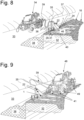
- the Figure 8 shows the overall situation from a greater distance.
- the subsoil 33 of the resulting trench shown here is often used as a so-called construction track after excavation. Trucks, dumpers, excavators or other machines then travel on this construction track for the construction of the rail line.
- the supply vehicle 34 as shown here as an example in use, can now be used to bond the ballast bed 32 in its left edge area.
- Such supply vehicles 34 with the entire equipment for carrying adhesive or adhesive components, for precisely mixing them and for pumping are already known.
- mixing is preferably carried out by static mixers using gear pumps and the quantity is metered using mass flow meters. This entire equipment as it is installed on such a vehicle is used in WO 2018/010860 A1 described and shown in detail.
- Single-component adhesives can also be used immediately with the same equipment without any modifications.
- the measuring wheel 24 or, depending on the model, the wheel 2, 3, 4 acting as a measuring wheel can be seen trailing behind the trolley 1, which provides reliable data on the speed of the trolley 1 to the electronic control unit on the supply vehicle 34 or on the portable electronic device.
- ballast bed shoulder 32 bonded in this way offers sufficient load-bearing capacity for trains of up to several hundred tons, depending on requirements.
- the material 38 can be excavated and transported away along the rail route. This area can therefore be exposed safely, while the adjacent rail 16 can still be used.
- the bonding of the ballast bed shoulder should ultimately make it possible to cut off and remove the hatched area 38 of the route, while maintaining the necessary stability of the route for the trains to pass.
- trolley 1 together with its boom 22 can be placed on a single rail 16 within a few seconds and can then be put into operation and vice versa, when a train is announced, this trolley 1 can just as quickly be taken off the rail 16 and removed so that a train can pass the work site unhindered.
- This railway carriage can then be loaded by a locomotive, a trolley or a track excavator in more or less at a constant distance from the rail trolley 1, pushed behind it or pulled ahead of it. It is also understood that these devices can also be transported by a self-propelled two-way vehicle, i.e. by a vehicle that can be driven on both the road and the rail. This vehicle then supplies the trolley device 1 with the already mixed adhesive or the adhesive components to be mixed via cables 36, 37 and hoses 35 in the same way as a road or off-road vehicle 34 traveling alongside the rail line.
- Such a vehicle 48 running on rails, here with rail wheels 49 that can be lowered hydraulically when required, is in Figure 9 shown as an example and it can travel behind the trolley 1 or alternatively travel ahead of the trolley 1.
- a vehicle 48 can be replaced by a railway carriage on which the entire device for tempering, pumping and mixing the components of the adhesive is built.
- This railway carriage then also carries the components for the energy supply, for example an internal combustion engine with generator and batteries for operating the electric pumps and for heating the adhesive to the ideal temperature.
- railway power can also be taken from the overhead line and made available for operating the device.
- Such a railway carriage can then travel on a track parallel to the track on which the trolley is placed, which it supplies with conditioned adhesive via pump hoses 35 and is connected to the trolley via cables 36, 37 for control and power supply. It is gradually pushed or pulled along the trolley by a draisine or a light locomotive and therefore does not have to move exactly uniformly with the trolley 1. If conditions permit, this railway carriage can also run on the same track on which trolley 1 is mounted. The rail-compatible road vehicle in Figure 9 is then simply replaced by such a railway carriage.
- the mixer Preferably a static mixer, in which the spray material is mixed, is attached directly to the rail trolley 1.
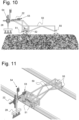
- the Figure 10 shows such a trolley 1 in the form of a light rail carriage on a rail, with a boom 50 for support on the other rail in an elevation.
- This trolley 1 or this rail carriage has no wheels rolling along the rail from below and can therefore be lifted vertically upwards from the rail at any time.
- a further advantage of this trolley or this rail carriage is that it can also roll over switches, in that the wheels 51, 52 rolling along the side of the rail head can be briefly lifted upwards, for example pneumatically or electrically, and after passing the switch are lowered back to their original state to roll along both sides of the rail head.
- the boom 22 is equipped with a device 53 for extending or shortening the boom 22, as well as with a device 54 for adjusting the height of the spray boom 28. These devices 53, 54 can be adjusted by electric motor, pneumatically or hydraulically.
- a support wheel 55 can be seen, with which the boom 50 is supported in a rolling manner on this opposite rail.
- the Figure 11 shows this rail car after Figure 10 on a rail, with a boom 50 for support on the opposite rail with, in the example shown, two support wheels 55 for the outer end of the boom 50.
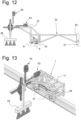
- Figure 12 shows the rail carriage with its two arms 22 and 50 in an enlarged view.
- the two wheels 51, 52 which roll on the two sides of the rail head 8 and thus stabilize the rail carriage about its vertical axis so that it cannot twist.
- the arm 50 with its support on the opposite rail 57, ensures stabilization about the axis along the rail.
- the spray bar 28 can also be installed on the rail carriage so that it can move.
- it can be mounted on an arm that extends across the entire width of the rail carriage, whereby the spray bar 28 can be mounted on this arm so that it can be moved by a motor, for example by means of an electric drive.
- the spray bar 28 can move back and forth evenly across the entire width of the ballast bed of a rail line and ensure that the adhesive penetrates evenly into the ballast bed.
- This boom can also be designed to pivot about a vertical axis, so that it no longer extends across the rail line, for example, but lengthways, along the rail.
- the spray bar 28 can then move back and forth along the boom at a uniform rate and thus bond a longitudinal section of the lateral ballast bed, i.e. a ballast bed shoulder, with a constant penetration depth of the adhesive.
- the Figure 13 shows the part of the rail car with the drive, that is to say its trolley 1, shown separately, in an enlarged and perspective view.
- the drive wheels 56 are housed inside, with which the trolley 1 rests on the rail, so that its entire weight ensures good adhesion. Between the two drive wheels 56, which can also act as measuring wheels, you can see the electric motor 11 for their drive.
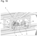
- FIG 14 This trolley shows the Figures 11 and 12 shown in an elevation. You can see the electric motor 11 and to the left of it the front drive wheel 56, as well as the two guide wheels 51, 52, which roll on both sides of the rail head 8. In Figure 15 is all this is shown enlarged, and in Figure 16 shown in a perspective view. Here you can see the drive belts or roller chains 14, via which the electric motor 11 drives the drive wheels 56.
- the drive wheels are equipped with a rubber tread 57 to ensure good adhesion.
Landscapes
- Engineering & Computer Science (AREA)
- Architecture (AREA)
- Civil Engineering (AREA)
- Structural Engineering (AREA)
- Transportation (AREA)
- Mechanical Engineering (AREA)
- Machines For Laying And Maintaining Railways (AREA)
- Spray Control Apparatus (AREA)
- Adhesives Or Adhesive Processes (AREA)
Applications Claiming Priority (3)
| Application Number | Priority Date | Filing Date | Title |
|---|---|---|---|
| CH001585/2020A CH718156B1 (de) | 2020-12-14 | 2020-12-14 | Einrichtung und Verfahren zum Austragen von Einkomponenten- oder Mehrkomponentenklebstoff auf ein Schotterbett einer Schienentrasse. |
| PCT/EP2021/085621 WO2022129001A1 (fr) | 2020-12-14 | 2021-12-14 | Dispositif et procédé pour appliquer un adhésif à un ou à plusieurs composants sur un lit de ballast et utilisation |
| EP21839845.1A EP4244426B1 (fr) | 2020-12-14 | 2021-12-14 | Dispositif et procédé pour appliquer un adhésif à un ou à plusieurs composants sur un lit de ballast |
Related Parent Applications (1)
| Application Number | Title | Priority Date | Filing Date |
|---|---|---|---|
| EP21839845.1A Division EP4244426B1 (fr) | 2020-12-14 | 2021-12-14 | Dispositif et procédé pour appliquer un adhésif à un ou à plusieurs composants sur un lit de ballast |
Publications (2)
| Publication Number | Publication Date |
|---|---|
| EP4477324A2 true EP4477324A2 (fr) | 2024-12-18 |
| EP4477324A3 EP4477324A3 (fr) | 2025-03-05 |
Family
ID=79288018
Family Applications (2)
| Application Number | Title | Priority Date | Filing Date |
|---|---|---|---|
| EP24203462.7A Pending EP4477324A3 (fr) | 2020-12-14 | 2021-12-14 | Dispositif pour appliquer un adhésif à un ou plusieurs composants sur un mélange granulaire, et procédé pour sa mise en oeuvre |
| EP21839845.1A Active EP4244426B1 (fr) | 2020-12-14 | 2021-12-14 | Dispositif et procédé pour appliquer un adhésif à un ou à plusieurs composants sur un lit de ballast |
Family Applications After (1)
| Application Number | Title | Priority Date | Filing Date |
|---|---|---|---|
| EP21839845.1A Active EP4244426B1 (fr) | 2020-12-14 | 2021-12-14 | Dispositif et procédé pour appliquer un adhésif à un ou à plusieurs composants sur un lit de ballast |
Country Status (13)
| Country | Link |
|---|---|
| EP (2) | EP4477324A3 (fr) |
| JP (1) | JP2023553526A (fr) |
| CN (1) | CN116964271A (fr) |
| AU (1) | AU2021404366A1 (fr) |
| CA (1) | CA3202188A1 (fr) |
| CH (1) | CH718156B1 (fr) |
| DE (1) | DE202021004316U1 (fr) |
| ES (1) | ES2992174T3 (fr) |
| HR (1) | HRP20241661T1 (fr) |
| HU (1) | HUE069374T2 (fr) |
| PL (1) | PL4244426T3 (fr) |
| RS (1) | RS66176B1 (fr) |
| WO (1) | WO2022129001A1 (fr) |
Families Citing this family (2)
| Publication number | Priority date | Publication date | Assignee | Title |
|---|---|---|---|---|
| AU2024293273A1 (en) * | 2023-07-19 | 2026-01-29 | Prodes Gmbh | Manipulation device and method for manipulating an elongate object |
| DE102024119728A1 (de) * | 2024-07-11 | 2026-01-15 | GETEK Gesellschaft für innovative Technik GmbH | Verfahren zur Sanierung und Stabilisierung eines Gleisbetts |
Citations (1)
| Publication number | Priority date | Publication date | Assignee | Title |
|---|---|---|---|---|
| WO2018010860A1 (fr) | 2016-04-19 | 2018-01-18 | Huerlimann Bautenschutz Ag | Dispositif de distribution d'adhésifs à plusieurs composants sur un mélange granulaire, ainsi que procédé de distribution et utilisation du dispositif |
Family Cites Families (13)
| Publication number | Priority date | Publication date | Assignee | Title |
|---|---|---|---|---|
| JPS6060358U (ja) * | 1982-12-02 | 1985-04-26 | 照陽興産有限会社 | レ−ル撒水機 |
| JP2881396B2 (ja) * | 1995-12-22 | 1999-04-12 | カワサキ技研株式会社 | 茶園管理装置の走行用レールにおけるストッパ装置 |
| JP3860969B2 (ja) * | 2001-01-24 | 2006-12-20 | 東海旅客鉄道株式会社 | 軌道盛土の安定化工法 |
| JP2007217539A (ja) * | 2006-02-16 | 2007-08-30 | Railway Technical Res Inst | 摩擦緩和材、摩擦緩和装置及び摩擦緩和方法 |
| KR101245762B1 (ko) * | 2010-12-17 | 2013-03-25 | 삼성중공업 주식회사 | 도장 장치의 도장 방법 |
| JP5850491B2 (ja) * | 2011-09-15 | 2016-02-03 | 株式会社コートテック | 床面用紫外線硬化型塗料施工装置 |
| US9920488B2 (en) * | 2014-04-08 | 2018-03-20 | Encore Rail Systems, Inc. | Railroad tie plugging system |
| JP3197306U (ja) * | 2015-02-19 | 2015-04-30 | 九鉄工業株式会社 | 軌道用運搬台車 |
| JP2021535300A (ja) * | 2018-08-30 | 2021-12-16 | ローベル バーンバウマシーネン ゲゼルシャフト ミット ベシュレンクテル ハフツングROBEL Bahnbaumaschinen GmbH | 軌道を加工する加工機械および方法 |
| CN109258606A (zh) * | 2018-11-08 | 2019-01-25 | 温瑞斌 | 一种设施大棚智能化喷洒装置 |
| KR102075149B1 (ko) * | 2019-09-03 | 2020-02-07 | 농업회사법인 (주)와이에이치산업 | 농약 살포용 노즐 조립체 및 그것을 포함하는 농약 살포 장치 |
| AU2020260510B2 (en) * | 2019-11-06 | 2022-03-31 | Bissell Inc. | Surface cleaning apparatus |
| CN113022642A (zh) * | 2021-03-29 | 2021-06-25 | 南京毕升创艺科技有限公司 | 一种钢轨交通钢轨无损探伤设备 |
-
2020
- 2020-12-14 CH CH001585/2020A patent/CH718156B1/de unknown
-
2021
- 2021-12-14 HU HUE21839845A patent/HUE069374T2/hu unknown
- 2021-12-14 PL PL21839845.1T patent/PL4244426T3/pl unknown
- 2021-12-14 HR HRP20241661TT patent/HRP20241661T1/hr unknown
- 2021-12-14 RS RS20241242A patent/RS66176B1/sr unknown
- 2021-12-14 DE DE202021004316.0U patent/DE202021004316U1/de active Active
- 2021-12-14 JP JP2023559167A patent/JP2023553526A/ja active Pending
- 2021-12-14 CA CA3202188A patent/CA3202188A1/fr active Pending
- 2021-12-14 EP EP24203462.7A patent/EP4477324A3/fr active Pending
- 2021-12-14 AU AU2021404366A patent/AU2021404366A1/en active Pending
- 2021-12-14 CN CN202180093744.0A patent/CN116964271A/zh active Pending
- 2021-12-14 ES ES21839845T patent/ES2992174T3/es active Active
- 2021-12-14 EP EP21839845.1A patent/EP4244426B1/fr active Active
- 2021-12-14 WO PCT/EP2021/085621 patent/WO2022129001A1/fr not_active Ceased
Patent Citations (1)
| Publication number | Priority date | Publication date | Assignee | Title |
|---|---|---|---|---|
| WO2018010860A1 (fr) | 2016-04-19 | 2018-01-18 | Huerlimann Bautenschutz Ag | Dispositif de distribution d'adhésifs à plusieurs composants sur un mélange granulaire, ainsi que procédé de distribution et utilisation du dispositif |
Also Published As
| Publication number | Publication date |
|---|---|
| JP2023553526A (ja) | 2023-12-21 |
| EP4244426B1 (fr) | 2024-10-02 |
| HRP20241661T1 (hr) | 2025-02-14 |
| AU2021404366A1 (en) | 2023-06-29 |
| CA3202188A1 (fr) | 2022-06-23 |
| CH718156A2 (de) | 2022-06-15 |
| DE202021004316U8 (de) | 2024-08-08 |
| EP4244426C0 (fr) | 2024-10-02 |
| HUE069374T2 (hu) | 2025-03-28 |
| EP4477324A3 (fr) | 2025-03-05 |
| CN116964271A (zh) | 2023-10-27 |
| RS66176B1 (sr) | 2024-12-31 |
| EP4244426A1 (fr) | 2023-09-20 |
| PL4244426T3 (pl) | 2025-02-10 |
| WO2022129001A1 (fr) | 2022-06-23 |
| DE202021004316U1 (de) | 2023-08-10 |
| CH718156B1 (de) | 2024-08-15 |
| ES2992174T3 (es) | 2024-12-10 |
| US20240044087A1 (en) | 2024-02-08 |
Similar Documents
| Publication | Publication Date | Title |
|---|---|---|
| EP3995217B1 (fr) | Dispositif pour appliquer des adhésifs à plusieurs composants sur un mélange granulaire, ainsi que procédé d'application et utilisation du dispositif | |
| EP3495566B1 (fr) | Dispositif et procédé de pose de câblé | |
| DE102007010101B4 (de) | Verfahren zur Herstellung eines Versorgungsleitungskanals sowie Zug bestehend aus Fahrzeugen zur Durchführung des Verfahrens | |
| EP4244426B1 (fr) | Dispositif et procédé pour appliquer un adhésif à un ou à plusieurs composants sur un lit de ballast | |
| WO2020191420A1 (fr) | Niveleuse de ballast | |
| DE102018201077B3 (de) | Vorrichtung für ein profilgesteuertes Einsanden und Verfüllen von Rohrleitungs- und Kabelgräben | |
| DE2937205A1 (de) | Kanalbaulaengsmaschine | |
| WO2007085571A2 (fr) | Voie pour le transport de conteneurs | |
| US12618200B2 (en) | Apparatus and method for applying single-component or multi-component adhesive to a ballast bed and use | |
| EP4552942A1 (fr) | Véhicule de travail, son utilisation et procédé de rénovation de voies ferrées | |
| DE102024133920A1 (de) | Verfahren zum Vorbereiten von Leitungstrassen für das Verlegen von Leitungen | |
| EA051142B1 (ru) | Устройство для нанесения одно- или многокомпонентного связующего материала на балластный слой рельсового пути железнодорожной линии | |
| DE2728001C3 (de) | Transporteinrichtung für Schüttgut, insbesondere zum Fördern extrem großer Frischbetonmengen zu einer Großbaustelle | |
| DE102008003951A1 (de) | Vorrichtung zum Verbringen von Baustoffen für einen Unterbau und/oder Oberbau einer Fahrbahn |
Legal Events
| Date | Code | Title | Description |
|---|---|---|---|
| PUAI | Public reference made under article 153(3) epc to a published international application that has entered the european phase |
Free format text: ORIGINAL CODE: 0009012 |
|
| STAA | Information on the status of an ep patent application or granted ep patent |
Free format text: STATUS: THE APPLICATION HAS BEEN PUBLISHED |
|
| AC | Divisional application: reference to earlier application |
Ref document number: 4244426 Country of ref document: EP Kind code of ref document: P |
|
| AK | Designated contracting states |
Kind code of ref document: A2 Designated state(s): AL AT BE BG CH CY CZ DE DK EE ES FI FR GB GR HR HU IE IS IT LI LT LU LV MC MK MT NL NO PL PT RO RS SE SI SK SM TR |
|
| REG | Reference to a national code |
Ref country code: DE Ref legal event code: R079 Free format text: PREVIOUS MAIN CLASS: B05B0013040000 Ipc: E01B0027000000 |
|
| PUAL | Search report despatched |
Free format text: ORIGINAL CODE: 0009013 |
|
| AK | Designated contracting states |
Kind code of ref document: A3 Designated state(s): AL AT BE BG CH CY CZ DE DK EE ES FI FR GB GR HR HU IE IS IT LI LT LU LV MC MK MT NL NO PL PT RO RS SE SI SK SM TR |
|
| RIC1 | Information provided on ipc code assigned before grant |
Ipc: B05B 13/04 20060101ALI20250130BHEP Ipc: B05B 13/00 20060101ALI20250130BHEP Ipc: E01B 27/00 20060101AFI20250130BHEP |
|
| STAA | Information on the status of an ep patent application or granted ep patent |
Free format text: STATUS: REQUEST FOR EXAMINATION WAS MADE |
|
| 17P | Request for examination filed |
Effective date: 20250905 |