EP4477352A1 - Outil d'usinage - Google Patents
Outil d'usinage Download PDFInfo
- Publication number
- EP4477352A1 EP4477352A1 EP24175681.6A EP24175681A EP4477352A1 EP 4477352 A1 EP4477352 A1 EP 4477352A1 EP 24175681 A EP24175681 A EP 24175681A EP 4477352 A1 EP4477352 A1 EP 4477352A1
- Authority
- EP
- European Patent Office
- Prior art keywords
- machining
- tools
- processing
- workpiece
- tool
- Prior art date
- Legal status (The legal status is an assumption and is not a legal conclusion. Google has not performed a legal analysis and makes no representation as to the accuracy of the status listed.)
- Withdrawn
Links
Images


Classifications
-
- B—PERFORMING OPERATIONS; TRANSPORTING
- B24—GRINDING; POLISHING
- B24D—TOOLS FOR GRINDING, BUFFING OR SHARPENING
- B24D13/00—Wheels having flexibly-acting working parts, e.g. buffing wheels; Mountings therefor
- B24D13/14—Wheels having flexibly-acting working parts, e.g. buffing wheels; Mountings therefor acting by the front face
- B24D13/142—Wheels of special form
-
- B—PERFORMING OPERATIONS; TRANSPORTING
- B24—GRINDING; POLISHING
- B24B—MACHINES, DEVICES, OR PROCESSES FOR GRINDING OR POLISHING; DRESSING OR CONDITIONING OF ABRADING SURFACES; FEEDING OF GRINDING, POLISHING, OR LAPPING AGENTS
- B24B29/00—Machines or devices for polishing surfaces on work by means of tools made of soft or flexible material with or without the application of solid or liquid polishing agents
- B24B29/005—Machines or devices for polishing surfaces on work by means of tools made of soft or flexible material with or without the application of solid or liquid polishing agents using brushes
-
- B—PERFORMING OPERATIONS; TRANSPORTING
- B24—GRINDING; POLISHING
- B24B—MACHINES, DEVICES, OR PROCESSES FOR GRINDING OR POLISHING; DRESSING OR CONDITIONING OF ABRADING SURFACES; FEEDING OF GRINDING, POLISHING, OR LAPPING AGENTS
- B24B41/00—Component parts such as frames, beds, carriages, headstocks
- B24B41/04—Headstocks; Working-spindles; Features relating thereto
- B24B41/047—Grinding heads for working on plane surfaces
-
- B—PERFORMING OPERATIONS; TRANSPORTING
- B24—GRINDING; POLISHING
- B24B—MACHINES, DEVICES, OR PROCESSES FOR GRINDING OR POLISHING; DRESSING OR CONDITIONING OF ABRADING SURFACES; FEEDING OF GRINDING, POLISHING, OR LAPPING AGENTS
- B24B7/00—Machines or devices designed for grinding plane surfaces on work, including polishing plane glass surfaces; Accessories therefor
- B24B7/005—Portal grinding machines
-
- B—PERFORMING OPERATIONS; TRANSPORTING
- B24—GRINDING; POLISHING
- B24B—MACHINES, DEVICES, OR PROCESSES FOR GRINDING OR POLISHING; DRESSING OR CONDITIONING OF ABRADING SURFACES; FEEDING OF GRINDING, POLISHING, OR LAPPING AGENTS
- B24B7/00—Machines or devices designed for grinding plane surfaces on work, including polishing plane glass surfaces; Accessories therefor
- B24B7/06—Machines or devices designed for grinding plane surfaces on work, including polishing plane glass surfaces; Accessories therefor involving conveyor belts, a sequence of travelling work-tables or the like
-
- B—PERFORMING OPERATIONS; TRANSPORTING
- B24—GRINDING; POLISHING
- B24D—TOOLS FOR GRINDING, BUFFING OR SHARPENING
- B24D13/00—Wheels having flexibly-acting working parts, e.g. buffing wheels; Mountings therefor
- B24D13/14—Wheels having flexibly-acting working parts, e.g. buffing wheels; Mountings therefor acting by the front face
- B24D13/145—Wheels having flexibly-acting working parts, e.g. buffing wheels; Mountings therefor acting by the front face having a brush-like working surface
-
- B—PERFORMING OPERATIONS; TRANSPORTING
- B24—GRINDING; POLISHING
- B24D—TOOLS FOR GRINDING, BUFFING OR SHARPENING
- B24D13/00—Wheels having flexibly-acting working parts, e.g. buffing wheels; Mountings therefor
- B24D13/14—Wheels having flexibly-acting working parts, e.g. buffing wheels; Mountings therefor acting by the front face
- B24D13/16—Wheels having flexibly-acting working parts, e.g. buffing wheels; Mountings therefor acting by the front face comprising pleated flaps or strips
-
- B—PERFORMING OPERATIONS; TRANSPORTING
- B24—GRINDING; POLISHING
- B24D—TOOLS FOR GRINDING, BUFFING OR SHARPENING
- B24D7/00—Bonded abrasive wheels, or wheels with inserted abrasive blocks, designed for acting otherwise than only by their periphery, e.g. by the front face; Bushings or mountings therefor
- B24D7/18—Wheels of special form
Definitions
- the invention relates to a machining tool for a device for machining flat workpieces, which comprises a carrier element with a connecting element for connection to a drive shaft that can be driven by a drive unit.
- the connecting element is designed for a rotationally fixed connection to the drive shaft and defines an axis of rotation of the machining tool.
- the carrier element is designed in a plane orthogonal to the axis of rotation symmetrically with respect to a first axis of symmetry running in the orthogonal plane and with respect to a second axis of symmetry running in the plane, wherein the first axis of symmetry and the second axis of symmetry intersect the axis of rotation.
- the invention further relates to a device for machining flat workpieces with at least two machining tools.
- machining flat workpieces are known in which rotating machining tools are used to machine the surface and/or the edges of the workpiece to be machined.
- One such device is known, for example, from the document DE 10 2007 022 194 B4
- the machining unit of this device comprises machining heads arranged in a row next to one another with planetary head gears through which the cylindrical rotating machining tools of adjacent machining heads mesh so that the machining circles of adjacent machining heads overlap. This means that the entire surface and/or all edges of the workpiece are machined without the need for several machining units arranged one behind the other.
- the cylindrical rotating processing tools are arranged in a row transverse to a processing direction of the workpieces to be processed.
- the entire processing unit can be arranged transversely moved back and forth to the machining direction of the workpiece in order to avoid machining gaps between the tools.
- the planetary head gears are relatively large and expensive. Replacing the machining tools is also complex. In devices where the entire machining unit is moved back and forth, an additional drive unit must be provided for this, with the machining unit itself containing the drive for driving the machining tools, so that large masses must be moved back and forth.
- a machining tool with the features of claim 1 and a device for machining flat workpieces ensure that the machining tools can be arranged next to one another in such a way that their machining circles overlap. This means that it is sufficient to provide a single row of machining tools arranged next to one another in order to evenly machine the entire surface and/or all edges of a flat workpiece.
- the longitudinal axes of the drive shafts connected to the machining tools or the axes of rotation of the machining tools are stationary.
- individual drive shafts can be moved along their longitudinal axis together with the machining tool. This can be done, for example, as in the document DE 10 2021 111 672 A1 described.
- the entire processing unit can be moved towards and away from a processing plane in which the workpiece to be processed is arranged. This can compensate for wear on the processing tools and/or adapt the device to the height of the flat workpieces to be processed.
- the processing tools enable a simple, cost-effective and space-saving construction of the device.
- An overlap of the machining circles of machining tools arranged next to one another is achieved in particular by the extension of the carrier element along the first axis of symmetry being longer than the extension of the carrier element along the second axis of symmetry.
- the connection of the connecting element of the machining tool to the drive shaft can be made via a screw connection, snap connection, clamp connection and/or plug connection in a manner known per se.
- the carrier plate of the machining tool preferably has a substantially elongated basic shape, i.e. the length of the carrier plate is greater than its width.
- the carrier element is rigidly connected to the connecting element, so that when the connecting element is connected to the drive shaft, the carrier element is not movable, in particular not pivotable, relative to the drive shaft.
- the side of the carrier element facing away from the connecting element is designed as a grinding tool, a brushing tool or a chipping tool or is connected to a grinding tool, brushing tool or chipping tool. This allows the flat workpiece to be easily machined.
- the processing elements of the grinding tool (abrasive), the brushing tool (bristles) or the chipping tool (chipping elements) can be rigidly connected to the carrier element.
- the processing elements themselves can, however, be elastically deformable. This makes it possible, in particular, to evenly process the edges of the flat workpiece.
- the brushing tool or the chipping tool When connecting the side of the carrier element facing away from the connecting element to the grinding tool, the brushing tool or the chipping tool, these can be rigidly connected to the carrier element.
- the processing elements of the grinding tool, the brushing tool or the chipping tool themselves can, however, be elastically be deformable. This makes it possible to evenly machine the edges of the flat workpiece.
- a large number of sanding sheets can be connected to the carrier element, with at least some of the sanding sheets being arranged in radial planes containing the axis of rotation, with support material, in particular support fleece, preferably being arranged between the sanding sheets.
- the sanding sheets can protrude from the carrier element perpendicularly in the direction of the workpiece to be processed. This enables good processing of the workpiece.
- the sanding sheets can easily adapt to the contour of the workpiece and process the edges of the workpiece evenly.
- as many of the sanding sheets connected to the carrier element are arranged in radial planes containing the axis of rotation.
- the sanding sheets are firmly or rigidly connected to the carrier element, i.e. the sanding sheets cannot be moved relative to the carrier element as a whole, in particular the end of each sanding sheet that is firmly or rigidly connected to the carrier element cannot be moved or pivoted relative to the connecting element. This allows the edges of the workpiece in particular to be processed evenly.
- the processing tool is designed as a brush tool
- a large number of bristles protruding vertically in the direction of the workpiece to be processed can be connected to the carrier element. This enables the workpiece to be processed well.
- the bristles can easily adapt to the contour of the workpiece and process the edges of the workpiece evenly.
- the bristles are firmly or rigidly connected to the carrier element, i.e. the bristles cannot be moved relative to the carrier element as a whole, in particular the end of each bristle that is firmly or rigidly connected to the carrier element cannot be moved or pivoted relative to the connecting element. This allows the edges of the workpiece in particular to be processed evenly.
- the processing tool is designed as a chipping tool
- chipping elements that protrude vertically in the direction of the workpiece to be processed can be firmly or rigidly connected to the carrier element.
- These chipping elements can be designed as cylindrical chipping elements and are also known as slag hammers. This allows slag that can form on the edges of a sheet metal blank during the corresponding cutting process to be removed easily and safely by chipping. This allows the edges of the workpiece to be processed evenly.
- the knock-off elements are firmly or rigidly connected to the carrier element, i.e. the knock-off elements cannot be moved relative to the carrier element as a whole, in particular the end of each knock-off element that is firmly or rigidly connected to the carrier element cannot be moved or pivoted relative to the connecting element. This allows the edges of the workpiece in particular to be processed evenly.
- the grinding sheets or bristles or chipping elements of the processing tools are preferably designed in such a way that they can be elastically deformed when processing the flat workpieces and can be deflected in such a way that they are pulled over the edges and the surface of the workpiece. This allows the edges of the workpiece in particular to be processed evenly.
- the device for machining the edges and surfaces of flat workpieces comprises at least two machining tools, each with a drive unit drivable drive shaft in a rotationally fixed manner at least in the drive direction of rotation of the drive shaft.
- the processing tools are each rotatably mounted by the drive shaft on the machine frame about a fixed axis of rotation perpendicular to the workpiece support. This enables a simple construction of the device, since in particular no planetary heads and no units for moving the processing units and tools back and forth are required.
- the workpiece support comprises at least one transport unit that defines a transport plane in which the workpieces to be processed are transported for processing in a transport direction.
- the transport unit comprises at least one transport element, which can comprise a conveyor belt or a transport roller, in particular a roller conveyor with several transport rollers. This allows the edges of the workpiece to be processed evenly.
- the at least two drive shafts with the processing tools are arranged in a single row transverse to the transport direction and/or processing direction of the workpiece to be processed, next to one another in a carrier unit, wherein the carrier unit is preferably aligned parallel to the workpiece support.
- the carrier unit, the drive shafts and the processing tools are part of a processing unit of the device.
- the processing unit can also comprise at least one drive unit for driving the drive shafts. This enables a compact design of the device and uniform processing of the edges.
- the drive shafts are first drive shafts
- the two processing tools are two first processing tools
- the device comprises at least two second processing tools according to one of claims 1 to 6.
- the second processing tools are each connected to a second drive shaft that can be driven by a drive unit in a rotationally fixed manner at least in the drive rotation direction of the drive shaft.
- the second processing tools are each connected to the machine frame by one of the second drive shafts by a distance to the workpiece support. vertical, stationary axis of rotation.
- the at least two second drive shafts are arranged in a second row transverse to the transport and/or processing direction of the workpiece to be processed, mounted next to one another in a second carrier unit, the second carrier unit preferably being arranged parallel to the workpiece support and in particular parallel to the first carrier unit.
- a processing unit of the device can comprise the first and the second carrier unit. This means that both rows of processing tools can be arranged compactly and in particular driven using just a single drive unit.
- first drive shafts with the first processing tools of the first row and the second drive shafts with the second processing tools of the second row have the same fixed distance from each other and the first drive shafts of the first row have a lateral offset transverse to the transport direction of half the distance between the drive shafts compared to the second drive shafts of the second row. This enables intensive processing of the flat workpiece with a simple device structure.
- first processing tools of the first row and the second processing tools of the second row are arranged and driven in such a way that the processing circles of the first processing tools of the first row overlap with the processing circles of the second processing tools of the second row.
- a transport element in particular a support roller, can be arranged between the processing tools of the first row and the processing tools of the second row. This enables a compact design of the device and safe processing of the workpieces.
- the drive shafts and the machining tools are are arranged next to one another and designed so that the spheres of action of their processing tools overlap, with the drive unit or the drive units preferably driving all drive shafts with the processing tools in the same direction of rotation. This ensures that both the edges and the surface of the workpiece are processed safely.
- the processing tools are arranged and designed in such a way that the grinding sheets or bristles or chipping elements of the processing tools are elastically deformed when processing the flat workpieces and are thereby deflected and pulled over the edge and the surface of the workpiece. This ensures that both the edges and the surface of the workpiece are processed safely.
- the workpiece support can comprise at least one transport unit with at least one transport element.
- the transport element can in particular comprise a conveyor belt or several transport rollers.
- the conveyor belt or the transport rollers define a transport plane in which the workpieces are transported for processing.
- the drive shafts of the processing tools can be arranged above the transport plane or above a processing plane, so that the processing tools at least contact the top of the workpiece and the upper edges of the workpiece.
- the processing tools contact at least the underside and the lower edges of the workpiece.
- the workpiece can then be pressed against the processing tools by a pressure belt arranged above the processing tools or by pressure rollers arranged above the processing tools.
- the pressure belt and/or the pressure rollers can be driven so that the workpiece is guided past the processing tools in the processing direction.
- There can be an adjustment unit by means of which the distance of the pressure belt or the pressure rollers from the processing plane and/or the transport plane can be adjusted depending on the thickness of the workpiece to be processed.
- other pressure means can also be used. be provided by which the workpiece to be machined is pressed against the machining tools.
- this can be sucked in with the help of a vacuum unit in such a way that it has a safe distance from the processing tools at least in the area of the processing tools arranged below the pressure belt.
- the pressure belt in the area of the processing tools does not sag so much that it comes into contact with the processing tools.
- the rotating pressure belt can be arranged or held at a safe distance from the processing tools at least in the area of the processing tools arranged below the pressure belt with the help of a magnet unit.
- the pressure belt in the area of the processing tools does not sag so much that it comes into contact with the processing tools.
- the pressure belt has in particular ferromagnetic components, in particular iron particles, or is designed as a steel belt.
- the magnet unit is in particular an electromagnet, which is preferably only activated when there is no workpiece in the area of the processing tools.
- Adjacent machining tools arranged in a row transverse to the machining direction are arranged and driven in a synchronized manner such that the adjacent machining tools mesh, i.e. that the machining circles of adjacent machining tools overlap.
- the size of the machining tools and the gaps between the adjacent machining tools and between the machining tools and the transport elements are adapted to the size of the workpieces to be machined in such a way that the workpieces do not fall into the gaps even when the workpieces are machined from below.
- a flat workpiece to be machined within the meaning of the invention is in particular a workpiece which is arranged during or for machining in such a way that its width and/or length are greater than its height.
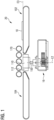
- FIG. 1 shows a schematic side view of a first device 20 for processing flat workpieces.
- a workpiece 10 to be processed rests on a first belt conveyor 102 and is moved with the aid of the latter in the processing and transport direction P1 of a processing unit 16 with processing tools 110, 112 arranged in a row.
- a further belt conveyor 104 is provided in order to transport the workpiece away after processing by the processing unit 16.
- Pressure rollers are arranged above the processing unit 16, which are preferably driven by means of a drive unit and, when the workpiece 10 is processed by the processing unit 16, exert a pressure force in the direction of the processing tools 110, 112 and a drive force in the processing direction P1 on the workpiece 10.
- the machining tools 110, 112 are each connected in a rotationally fixed manner to a drive shaft 160.
- the drive shafts 150 are connected via a gear 108, preferably via a gear transmission with spur gears, to a Figure 5 not shown drive unit of the processing unit 16 in such a way that all drive shafts 150 and thus all processing tools 110, 112 are driven at the same speed. neighboring machining tools 110, 112 are thus driven in a synchronized manner.
- the machining tools 110, 112 mesh, ie their machining circles overlap.
- machining tools 110, 112 are arranged offset by 90° from one another, ie the machining tool 112 is arranged 90° around its axis of rotation in a clockwise direction P2 relative to the machining tool 110.
- the machining tools 110, 112 are connected to their respective drive shaft 150 in a rotationally fixed and rigid manner via a positive or non-positive connection.
- the center axes of the drive shafts 150 of the single row of machining tools 110 to 128 in this embodiment and thus the axes of rotation of the machining tools 110 to 128 are arranged in a first plane E2 orthogonal to the machining direction P1.
- a control unit controls a drive unit for changing the distance of the pressure rollers 170 to the transport plane E3 defined by the belt conveyor 102 starting from the determined height in such a way that the pressure rollers 170 are moved upwards before the workpiece 10 reaches the first pressure roller 170 serving as an infeed roller.
- the processing unit 16 can be moved with the aid of a drive unit (not shown) in such a way that a processing plane defined by the upper edge of the processing tools 110 to 128 can be moved relative to the transport plane E3.
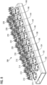
- FIG 2 shows a schematic perspective view of the first processing unit 16 with first processing tools 110 to 148 of the device 20 arranged in the single row according to Figure 1 .
- the processing tools 110 to 128 are designed as grinding tools, wherein a plurality of grinding sheets are connected to a carrier element of the respective processing tool 110 to 148, which are inserted into the are arranged in radial planes containing the axis of rotation, wherein support material is preferably arranged between the sanding sheets, in particular support fleece.
- One side of the sanding sheets is fixed and thus rigidly connected to the carrier element of the processing tool 110 to 128.
- the processing tools 110 to 128 all have the same direction of rotation.
- Figure 3 shows a schematic side view of a second device 30 for machining flat workpieces 10.
- the second device 30 differs from the first device 20 by a second row of machining tools 130 to 148.
- the second row is upstream of the first row in a plane E1 that is orthogonal to the transport plane E3 and the transport direction P1.
- a support roller 28 is arranged, which serves to support and guide the workpiece 10 to be machined.
- the machining unit 26 can be moved with the aid of a drive unit (not shown) in such a way that a machining plane defined by the upper edge of the machining tools 110 to 148 can be displaced relative to the transport plane E3.
- the support roller 26 is arranged in the transport plane E3, ie a tangent of the support roller lies in the transport plane E3.
- the support roller 26 can be moved with the aid of a drive unit such that a tangent of the support roller 26 running parallel to the processing plane E3 can be arranged at a distance from the transport plane E3. The distance of the tangent to the transport plane E3 can thus be adjusted with the aid of the drive unit.
- the remaining structure and function of the processing unit 26 are consistent with the processing unit 16 according to the Figures 1 and 2 Likewise, the remaining structure and function of the second device 30 correspond to the first device 20 according to the Figures 1 and 2 Elements with the same structure or the same function have the same reference symbols.
- Figure 4 shows a schematic perspective view of a second processing unit 26 with processing tools 110 to 148 arranged in two rows one behind the other of the second device 30 according to Figure 3 .
- the machining circles of adjacent machining tools 110 to 148 of each row overlap so that there are no gaps between the machining areas of adjacent machining tools 110 to 148, so that when machining the workpiece 10, its surface and the edges of the workpiece 10 are completely machined by the machining tools 110 to 148 of only one row.
- the machining tools 110 to 148 of the first row and the second row all have the same direction of rotation.
- all machining tools 110 to 148 in one row have the same direction of rotation P2 and the machining tools 110 to 148 in the other row have the opposite direction of rotation. As a result, the edges of the workpiece 10 are machined relatively evenly.
- the processing tools 110 to 148 can also be designed as brushing tools, in which case a plurality of bristles projecting vertically in the direction of the workpiece 10 to be processed are firmly connected to a carrier element of each processing tool.
- the processing tools 110 to 148 can also be designed as chipping tools, in which case a plurality of chipping elements projecting vertically in the direction of the workpiece 10 to be processed are firmly connected to a carrier element of each processing tool.
- the workpiece 10 is machined from below, ie the underside and/or the lower edges of the workpiece 10 are machined using the machining tools 110 to 148.
- the machining unit 16, 26 is arranged above the machining plane E3 and the workpiece 10 to be machined is machined below the machining unit 16, 26. passed, for example on a continuous belt conveyor 102 or on a roller conveyor.
- the planes E1 and E2 are orthogonal to the transport plane E3 and orthogonal to the processing and transport direction P1.
- individual drive shafts 150, 160 can be moved along their longitudinal axis together with the machining tool 110 to 148, 210 to 248 for height compensation and/or to adapt to contours of the workpiece 10. This can be done, for example, as in the document DE 10 2021 111 672 A1 described.
- FIG. 5 shows a schematic side view of a third device 100 for processing flat workpieces.
- the workpiece 10 to be processed rests on the first belt conveyor 102 and is moved with its help in the processing and transport direction P1 of a third processing unit 106 with processing tools 110, 112, 130 arranged in two rows.
- the further belt conveyor 104 is provided to transport the workpiece 10 away after processing by the processing unit 106.
- Pressure rollers are arranged above the processing unit 106, which are preferably driven by means of a drive unit and, when the workpiece 10 is processed by the processing unit 106, exert a pressing force in the direction of the processing tools 110, 112, 130 and a driving force in the processing direction P1 on the workpiece 10.
- the machining tools 110, 112, 130 are each connected in a rotationally fixed manner to a drive shaft 150, 160.
- the drive shafts 150, 160 are connected via a gear 108, preferably via a gear transmission with spur gears, to a Figure 5 not shown drive unit of the processing unit 106 in such a way that all drive shafts 150, 160 and thus all processing tools 110, 112, 130 are driven at the same speed.
- Immediately adjacent processing tools 110, 112 are thus driven synchronously.
- the processing tools 110, 112 mesh, ie their processing circles overlap.
- processing tools 110, 112 are arranged offset by 90° to one another, ie the processing tool 112 is rotated 90° around its axis of rotation in a clockwise direction P2 relative to the Machining tool 110 is arranged.
- the machining tools 110, 112 are connected in a rotationally fixed and rigid manner to their respective drive shafts 150, 160 via a positive or non-positive connection.
- the center axes of the drive shafts 160 of the first row with machining tools 130 to 148 and thus the axes of rotation of the machining tools 130 to 148 are arranged in a first plane E1 orthogonal to the machining direction P1.
- the center axes of the drive shafts 150 of the second row with machining tools 110 to 128 and thus the axes of rotation of the machining tools 110 to 128 are arranged in a first plane E2 orthogonal to the machining direction P1 downstream of the plane E1.
- a support and guide element 103 is arranged between the first belt conveyor 102 and the processing unit 106, by means of which the workpiece 10 is precisely fed to the processing unit 106.
- the support and guide element 103 can be dispensed with.
- a control unit controls a drive unit for changing the distance of the pressure rollers 170 to the transport plane E3 defined by the belt conveyor 102 starting from the determined height in such a way that the pressure rollers 170 are moved upwards before the workpiece 10 reaches the first pressure roller 170 serving as an infeed roller.
- the processing unit 106 can be moved with the aid of a drive unit (not shown) in such a way that a processing plane defined by the upper edge of the processing tools 110 to 148 can be moved relative to the transport plane E3.
- FIG 6 shows a schematic perspective view of the third processing unit 106 with first machining tools 110 to 148 of the device 100 arranged in two rows one behind the other Figure 1
- the processing tools 110 to 148 are designed as grinding tools, wherein a plurality of grinding sheets are firmly connected to a carrier element of the respective processing tool 110 to 148, which are arranged in radial planes containing the axis of rotation, wherein support material, in particular support fleece, is preferably arranged between the grinding sheets.
- support material in particular support fleece
- Figure 7 shows a schematic side view of a fourth device 200 for machining flat workpieces 10.
- the fourth device 200 differs from the third device by the machining tools 210 to 248 of the machining unit 206.
- the remaining structure and function of the machining unit 206 are consistent with the machining unit 106 according to the Figures 5 and 6
- the remaining structure and function of the fourth device 200 correspond to the third device 100 according to the Figures 5 and 6 Elements with the same structure or the same function have the same reference symbols.
- Figure 8 shows a schematic perspective view of a fourth processing unit 206 with second processing tools 210 to 248 arranged in two rows one behind the other of the fourth device 200 according to Figure 7
- the processing tools 210 to 248 are designed as cutting tools, with a plurality of cutting elements projecting vertically in the direction of the workpiece to be processed being firmly connected to a carrier element of the respective processing tool 210 to 248.
- One of these stop elements is designated by the reference numeral 211 as an example.
- the machining circles of adjacent machining tools 110 to 148, 210 to 248 of each row overlap so that there are no gaps between the machining areas of adjacent machining tools 110 to 148, 210 to 248, so that machining of the workpiece 10, its surface and the edges of the workpiece 10 by the machining tools 110 to 148 can only be completely machined in one row.
- the machining tools 110 to 148, 210 to 248 of the first row and the second row all have the same direction of rotation.
- all machining tools 110 to 148, 210 to 248 of one row have the same direction of rotation P2 and the machining tools 110 to 148, 210 to 248 of the other row have the opposite direction of rotation.
- the processing tools 110 to 148, 210 to 248 can also be designed as brushing tools, wherein a plurality of bristles projecting perpendicularly in the direction of the workpiece 10 to be processed are then firmly connected to a carrier element of each processing tool.
- the workpiece 10 is machined from below, i.e. the underside and/or the lower edges of the workpiece 10 are machined using the machining tools 110 to 148, 210 to 248.
- the machining unit 106, 206 is arranged above the transport plane E3 and the workpiece 10 to be machined is guided past the machining unit 106, 206 for machining, for example on a continuous belt conveyor 102 or on a roller conveyor.
- the planes E1 and E2 are orthogonal to the transport plane E3 and orthogonal to the machining and transport direction P1.
- individual drive shafts 150, 160 can be moved along their longitudinal axis together with the machining tool 110 to 148, 210 to 248 for height compensation and/or for adaptation to contours of the workpiece 10. This can be done, for example, as in the document DE 10 2021 111 672 A1 described.
- the processing units 106, 206 can each be moved with the aid of a drive unit (not shown) in such a way that a processing plane defined by the upper edge of the processing tools 110 to 148, 210 to 248 can be moved relative to the transport plane E3.
- a drive unit not shown
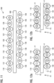
- Figure 9 shows a schematic plan view of the third machining unit 106 with machining tools 110 to 148 arranged one behind the other in two rows in an exemplary starting position.
- the distance between the axes of rotation D of all adjacent machining tools 110 to 128; 130 to 148 of each row is the same.
- the axes of rotation D of adjacent machining tools 130 to 148 in the first row have the same distance transverse to the machining direction P1 as the axes of rotation D of adjacent machining tools 110 to 128 in the first row.
- the distance between the plane E1 and the plane E2 is equal to the distance between adjacent machining tools 110, 122; 130, 132.
- the planes E1 and E2 are further apart than the distance between adjacent machining tools 110, 122; 130, 132.
- the two rows have a lateral offset of half the distance of the rotation axes of adjacent machining tools 110 to 128, 130 to 148.
- the rotation axis D of the machining tool 130 is arranged centrally between the rotation axes D of the machining tools 110, 112. This can be done in particular by projecting the rotation axes of the rotation axes D of the machining tools 130 to 148 into the plane E2, in which the rotation axes D of the machining tools 110 to 128 of the second row are arranged.
- Figure 10a shows a part of the machining tools 110 to 116, 130 to 136 after Figure 9 when the machining tools 130 to 136 of the first row are rotated from the Figure 9 shown starting position by 10° counterclockwise and the machining tools 110 to 116 of the second row from the Figure 9 shown starting position by 10° clockwise.
- Figure 10b shows a part of the machining tools 110 to 116, 130 to 136 after Figure 9 upon rotation of the machining tools 130 to 136 of the first row and the machining tools 110 to 116 of the second row from the Figure 9 shown starting position by 10° clockwise.
- the machining circles of the machining tools 110 to 116, 130 to 136 are in the Figures 10a and 10b designated by the reference symbol K.
- Figure 11 shows a schematic top view of the further processing unit 306 with processing tools 110 to 148 arranged in two rows one behind the other.
- a freely rotatable support roller 308 is arranged between the two rows.
- the support roller is driven and/or several support rollers 308 or a belt conveyor are arranged between the two rows.
- the processing unit 306 essentially corresponds to the processing unit 26 according to Figure 3 agree.
- Figure 12a shows a part of the machining tools 110 to 116, 130 to 136 after Figure 11 upon rotation of the machining tools 130 to 136 of the first row by 10° counterclockwise and of the machining tools 110 to 116 of the second row by 10° clockwise, wherein the support roller 308 is arranged between the machining tools 110 to 116, 130 to 136 of the two rows.
- Figure 12b shows a part of the machining tools 110 to 116, 130 to 136 after Figure 11 upon rotation of the machining tools 130 to 136 of the first row and the machining tools 110 to 116 of the second row by 10° in a clockwise direction, wherein the support roller 308 is arranged between the machining tools 110 to 116, 130 to 136 of the two rows.
- Figure 13a shows a part of the machining tools 110 to 116 of the second row after Figure 9 , wherein the contact areas of the machining tools 110 to 116 on the front edge of the workpiece 10 to be machined are schematically shown by thick solid lines and on the rear edge of the workpiece 10 to be machined by dotted lines with a simultaneous drive of the machining tools 110 to 116 in a clockwise direction P2. The edges of the workpiece 10 are thus machined evenly.
- Figure 13b shows a part of the machining tools 110 to 116 of the second row after Figure 9 , wherein the contact areas of the machining tools 110 to 116 at the front edge of the workpiece 10 to be machined are indicated by thick solid lines and at the rear edge of the workpiece 10 to be machined are shown schematically by dotted lines with a counter-rotating drive of the machining tools P2, P3.
- Figure 14 shows a side view of the third machining unit 106 with a breakout on the machining tool 130.
- Figure 15 shows an enlarged sectional view of the machining tool 130 arranged in the cutout.
- the machining tool is connected to the drive shaft 160 with a screw 130a.
- the screw 130a is screwed through an opening 130b into an internal thread 160a introduced into a front opening of the drive shaft 160.
- the screw 130a and the opening 130b form a connecting element 130e, by means of which a carrier plate 130c of the machining tool 130 can be rigidly and thus also rotationally connected to the drive shaft 160.
- the connection between the drive shaft 160 and the machining tool 130 is made via a force-locking connection.
- a form-locking connection can also be provided for connecting the drive shaft 160 and the machining tool 130.
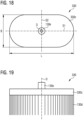
- Figure 16 shows a schematic plan view of the machining tool 130 and Figure 17 a schematic side view of the machining tool 130.
- the carrier plate 130c of the machining tool 130 has a first elliptical basic shape with the length L and the width B.
- the width B is 50% of the length. In other embodiments, the width has a value in the range of 30% to 60% of the length.
- the carrier plate 130c is symmetrical to both the axis of symmetry S1 and the axis of symmetry S2.
- the axes of symmetry S1, S2 run in a plane orthogonal to the axis of rotation D, which runs through the carrier plate 130c. Both the axis of symmetry S1 and the axis of symmetry S2 intersect the axis of rotation D at an angle of 90°.
- FIG 18 shows a schematic plan view of a machining tool 330 and Figure 19 a schematic side view of the machining tool 330.
- a carrier plate 330c of the machining tool 330 has a second basic shape with the length L and the width B.
- the width B is 50% of the length. In other embodiments, the width has a value in the range of 30% to 60% of the length.
- the carrier plate 330c is both symmetrical to the symmetry axis S1 and to the symmetry axis S2.
- the symmetry axes S1, S2 run in a plane orthogonal to the rotation axis D, which runs through the carrier plate 330c. Both the symmetry axis S1 and the symmetry axis S2 intersect the rotation axis D at an angle of 90°.
- the second basic shape has a rectangular central section, to which semicircular sections are connected on both sides in the longitudinal direction.
- Figure 20 shows a schematic plan view of a machining tool 340 and Figure 21 a schematic side view of the machining tool 340.
- a carrier plate 340c of the machining tool 340 has a third basic shape with the length L and the width B.
- the width B is 50% of the length. In other embodiments, the width has a value in the range of 30% to 60% of the length.
- the carrier plate 340c is symmetrical to both the axis of symmetry S1 and the axis of symmetry S2.
- the axes of symmetry S1, S2 run in a plane orthogonal to the axis of rotation D, which runs through the carrier plate 340c.
- the third basic shape has a rectangular central section, to which trapezoidal sections tapering towards the ends are connected in the longitudinal direction on both sides.
- FIG 22 shows a schematic plan view of a machining tool 350 and Figure 23 a schematic side view of the machining tool 350.
- a carrier plate 350c of the machining tool 350 has a fourth basic shape with the length L and the width B.
- the width B is 50% of the length. In other embodiments, the width has a value in the range of 30% to 60% of the length.
- the carrier plate 350c is symmetrical to both the axis of symmetry S1 and the axis of symmetry S2.
- the axes of symmetry S1, S2 run in a plane orthogonal to the axis of rotation D, which runs through the carrier plate 350c. Both the axis of symmetry S1 and the axis of symmetry S2 intersect the axis of rotation D at an angle of 90°.
- the fourth basic shape has a rectangular central section, to which triangular cuts are connected in the longitudinal direction on both sides, tapering towards the ends. The triangular cuts are equilateral or at least isosceles.
- Figure 24 shows a schematic top view of a machining tool 360 and Figure 25 a schematic side view of the machining tool 360.
- a carrier plate 360c of the machining tool 360 has a fifth basic shape with the length L and the width B.
- the width B is 50% of the length. In other embodiments, the width has a value in the range of 30% to 60% of the length.
- the carrier plate 360c is symmetrical to both the axis of symmetry S1 and the axis of symmetry S2.
- the axes of symmetry S1, S2 run in a plane orthogonal to the axis of rotation D, which runs through the carrier plate 360c. Both the axis of symmetry S1 and the axis of symmetry S2 intersect the axis of rotation D at an angle of 90°.
- the fifth basic shape is rectangular.
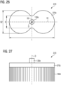
- Figure 26 shows a schematic plan view of a machining tool 370 and Figure 27 a schematic side view of the machining tool 370.
- a carrier plate 370c of the machining tool 370 has a sixth basic shape with the length L and the width B.
- the width B at the axis of symmetry S2 is 25% of the length. In other embodiments, the width at the axis of symmetry has a value in the range of 10% to 50% of the length.
- the carrier plate 370c is symmetrical to both the axis of symmetry S1 and the axis of symmetry S2.
- the axes of symmetry S1, S2 run in a plane orthogonal to the axis of rotation D, which runs through the carrier plate 370c.
- the sixth basic shape has the outline of the number 8.
- the maximum width B2 of the carrier plate 370c has a value in the range of 30% to 60% of the length L.
- processing means such as chipping means or chipping pins 211 and/or bristles, can be connected to the respective carrier plates 330c to 370c instead of the grinding sheets 130d or in addition to the grinding sheets 130d.
- Figure 28 shows a schematic view of the first machining tool 130 according to the Figures 5 and 6 .
- the arrangement of the grinding wheels 130d which protrude perpendicularly in the direction of the workpiece 10 to be machined from the carrier plate 130c and are connected to it, is clearly visible.
- between the Sanding sheets 130d also have a supporting fleece.
- Figure 29 shows a schematic view of the second machining tool 230 according to the Figures 7 and 8 .
- the arrangement of the cylindrical knock-off elements 211 which protrude perpendicularly from the carrier plate 130c in the direction of the workpiece 10 to be machined and are connected to it, is clearly visible.
- These elements are also referred to as knock-off pins.
- the knock-off pins can also have a different shape, in particular a different cross-section.
- the length L is greater than the width B and greater than the maximum width B2.
- the processing tools 110 to 148, 210 to 248 contact at least the underside and the lower edges of the workpiece 10.
- the workpiece 10 can then be pressed against the processing tools 110 to 148, 210 to 248 by a pressure roller 170 arranged above the processing tools 110 to 148, 210 to 248 or by at least one pressure belt arranged above the processing tools 110 to 148, 210 to 248.
- the pressure belt and/or the pressure rollers 170 can be driven so that the workpiece 10 is guided past the processing tools 110 to 148, 210 to 248 in the processing direction P1.
- An adjustment unit can be provided by which the distance of the pressure belt or the pressure rollers 170 from the processing plane and/or the transport plane E3 can be adjusted depending on the thickness of the workpiece 10 to be processed.
- other pressure means can also be provided by which the workpiece 10 to be processed is pressed against the processing tools 110 to 148, 210 to 248.
- this can be sucked in with the aid of a vacuum unit in such a way that it has a safe distance from the processing tools 110 to 148, 210 to 248 at least in the area of the processing tools 110 to 148, 210 to 248 arranged below the pressure belt.
- the pressure belt in the area of the processing tools 110 to 148, 210 to 248 does not sag in such a way that it contacts the processing tools 110 to 148, 210 to 248.
- the rotating pressure belt can be arranged or held at a safe distance from the processing tools 110 to 148, 210 to 248, at least in the area of the processing tools 110 to 148, 210 to 248 arranged below the pressure belt, using a magnet unit.
- the pressure belt in the area of the processing tools 110 to 148, 210 to 248 does not sag in such a way that it contacts the processing tools 110 to 148, 210 to 248.
- the pressure belt has in particular ferromagnetic components, in particular iron particles, or is designed as a steel belt.
- the magnet unit is in particular an electromagnet, which is preferably only activated when there is no workpiece in the area of the processing tools 110 to 148, 210 to 248.
Landscapes
- Engineering & Computer Science (AREA)
- Mechanical Engineering (AREA)
- Finish Polishing, Edge Sharpening, And Grinding By Specific Grinding Devices (AREA)
- Manipulator (AREA)
Applications Claiming Priority (1)
| Application Number | Priority Date | Filing Date | Title |
|---|---|---|---|
| DE102023114964.4A DE102023114964A1 (de) | 2023-06-07 | 2023-06-07 | Bearbeitungswerkzeug |
Publications (1)
| Publication Number | Publication Date |
|---|---|
| EP4477352A1 true EP4477352A1 (fr) | 2024-12-18 |
Family
ID=91082241
Family Applications (1)
| Application Number | Title | Priority Date | Filing Date |
|---|---|---|---|
| EP24175681.6A Withdrawn EP4477352A1 (fr) | 2023-06-07 | 2024-05-14 | Outil d'usinage |
Country Status (2)
| Country | Link |
|---|---|
| EP (1) | EP4477352A1 (fr) |
| DE (2) | DE102023114964A1 (fr) |
Citations (5)
| Publication number | Priority date | Publication date | Assignee | Title |
|---|---|---|---|---|
| US2597182A (en) * | 1949-03-31 | 1952-05-20 | Libbey Owens Ford Glass Co | Surfacing glass sheets or plates |
| DE1084606B (de) * | 1951-05-16 | 1960-06-30 | Glaceries De La Sambre Sa | Einrichtung zum kontinuierlichen Schleifen und bzw. oder Polieren der beiden Flaechen eines Glasbandes |
| DE102007022194B4 (de) | 2007-05-11 | 2015-05-13 | Hans Weber Maschinenfabrik Gmbh | Vorrichtung zum Bearbeiten der Kanten und Oberflächen flächiger Werkstücke |
| KR101849408B1 (ko) * | 2010-12-27 | 2018-04-16 | 아사히 가라스 가부시키가이샤 | 유리판의 연속 연마 장치 및 유리판의 연속 연마 방법 |
| DE102021111672A1 (de) | 2021-05-05 | 2022-11-10 | Georg Weber | Vorrichtung zum Bearbeiten von flächigen Werkstücken |
Family Cites Families (2)
| Publication number | Priority date | Publication date | Assignee | Title |
|---|---|---|---|---|
| US1142570A (en) * | 1912-06-18 | 1915-06-08 | William La Hodny | Polishing-machine. |
| EP1500467A1 (fr) * | 2003-07-22 | 2005-01-26 | S.L.M. Immobiliare S.r.l. | Appareil et procédé de traitement de surface d'une plaques metallique |
-
2023
- 2023-06-07 DE DE102023114964.4A patent/DE102023114964A1/de active Pending
-
2024
- 2024-05-14 EP EP24175681.6A patent/EP4477352A1/fr not_active Withdrawn
- 2024-05-14 DE DE202024002575.6U patent/DE202024002575U1/de active Active
Patent Citations (5)
| Publication number | Priority date | Publication date | Assignee | Title |
|---|---|---|---|---|
| US2597182A (en) * | 1949-03-31 | 1952-05-20 | Libbey Owens Ford Glass Co | Surfacing glass sheets or plates |
| DE1084606B (de) * | 1951-05-16 | 1960-06-30 | Glaceries De La Sambre Sa | Einrichtung zum kontinuierlichen Schleifen und bzw. oder Polieren der beiden Flaechen eines Glasbandes |
| DE102007022194B4 (de) | 2007-05-11 | 2015-05-13 | Hans Weber Maschinenfabrik Gmbh | Vorrichtung zum Bearbeiten der Kanten und Oberflächen flächiger Werkstücke |
| KR101849408B1 (ko) * | 2010-12-27 | 2018-04-16 | 아사히 가라스 가부시키가이샤 | 유리판의 연속 연마 장치 및 유리판의 연속 연마 방법 |
| DE102021111672A1 (de) | 2021-05-05 | 2022-11-10 | Georg Weber | Vorrichtung zum Bearbeiten von flächigen Werkstücken |
Also Published As
| Publication number | Publication date |
|---|---|
| DE102023114964A1 (de) | 2024-12-12 |
| DE202024002575U1 (de) | 2025-08-18 |
Similar Documents
| Publication | Publication Date | Title |
|---|---|---|
| DE2520170A1 (de) | Vorrichtung zum antrieb von umlaufenden werkzeugen fuer radiale einzeleinstellung und der ihnen zugeordneten gegenbauteile | |
| DE3152612C2 (fr) | ||
| EP2353810A1 (fr) | Dispositif destiné au traitement d'une bande de matériau | |
| DE102020126782C5 (de) | Applikationseinheit, Verfahren zum Betreiben einer Applikationseinheit sowie eine Verpackungsmaschine mit einer Applikationseinheit | |
| WO2019036736A1 (fr) | Système de préparation destiné à fabriquer une tige d'enroulement pour un moteur électrique, et procédé de fabrication d'une tige d'enroulement | |
| DE2644900B2 (de) | Profiliermaschine | |
| DE29911152U1 (de) | Werkzeugvorrichtung zur spanenden Bearbeitung tafelförmiger Werkstücke | |
| DE3029143A1 (de) | Rotierende stanzvorrichtung | |
| DE2533484A1 (de) | Walzmaschine zum walzen von ringfoermigen werkstuecken | |
| EP4477352A1 (fr) | Outil d'usinage | |
| DE3427368C1 (de) | Vorrichtung zum Bearbeiten von Zahnraedern | |
| EP0293574B1 (fr) | Machine à meuler à bande | |
| EP3797893B1 (fr) | Dispositif de découpage fin / découpage normal d' ébauches d'une bande métallique ainsi que de travail en plusieurs étapes des ébauches au moyen d' outils de coupe et de façonnage | |
| WO2018162642A1 (fr) | Procédé et dispositif de fabrication de crémaillères | |
| DE69703978T2 (de) | Vorrichtung zum regeln der grösse eines werkzeugmaschinen-blechhalters | |
| EP0937673A2 (fr) | Procédé et dispositif pour déplacer des barres à pinces dans une machine de traitement de feuilles | |
| WO2022067363A1 (fr) | Dispositif de pliage doté d'une unité de butée arrière | |
| DE68910347T2 (de) | Herstellung von elektrischen Stiften. | |
| EP1235730B1 (fr) | Dispositif de separation de bandes et utilisations dudit dispositif | |
| EP4442418B1 (fr) | Dispositif de fraisage de bord et procédé de fraisage de bord | |
| DE2062982A1 (de) | Papierlochmaschine | |
| DE3006832C2 (de) | Maschine zum Entgraten | |
| DE2258647A1 (de) | Presse mit zwei um die eine bzw. andere von zwei parallelen drehachsen synchron rotierenden werkzeugtraegern | |
| DE29621385U1 (de) | Positioniereinrichtung für Querdrähte | |
| DE505152C (de) | Maschine zur Herstellung von Bonbons aus einem Massestrang |
Legal Events
| Date | Code | Title | Description |
|---|---|---|---|
| PUAI | Public reference made under article 153(3) epc to a published international application that has entered the european phase |
Free format text: ORIGINAL CODE: 0009012 |
|
| STAA | Information on the status of an ep patent application or granted ep patent |
Free format text: STATUS: THE APPLICATION HAS BEEN PUBLISHED |
|
| AK | Designated contracting states |
Kind code of ref document: A1 Designated state(s): AL AT BE BG CH CY CZ DE DK EE ES FI FR GB GR HR HU IE IS IT LI LT LU LV MC ME MK MT NL NO PL PT RO RS SE SI SK SM TR |
|
| STAA | Information on the status of an ep patent application or granted ep patent |
Free format text: STATUS: THE APPLICATION IS DEEMED TO BE WITHDRAWN |
|
| 18D | Application deemed to be withdrawn |
Effective date: 20250619 |