EP4477395A2 - Verfahren zur herstellung einer vorrichtung aus verbundmaterial, muster, vorrichtung - Google Patents
Verfahren zur herstellung einer vorrichtung aus verbundmaterial, muster, vorrichtung Download PDFInfo
- Publication number
- EP4477395A2 EP4477395A2 EP24210461.0A EP24210461A EP4477395A2 EP 4477395 A2 EP4477395 A2 EP 4477395A2 EP 24210461 A EP24210461 A EP 24210461A EP 4477395 A2 EP4477395 A2 EP 4477395A2
- Authority
- EP
- European Patent Office
- Prior art keywords
- pattern
- inserts
- mold
- range
- tolerance
- Prior art date
- Legal status (The legal status is an assumption and is not a legal conclusion. Google has not performed a legal analysis and makes no representation as to the accuracy of the status listed.)
- Pending
Links
Images


Classifications
-
- B—PERFORMING OPERATIONS; TRANSPORTING
- B29—WORKING OF PLASTICS; WORKING OF SUBSTANCES IN A PLASTIC STATE IN GENERAL
- B29C—SHAPING OR JOINING OF PLASTICS; SHAPING OF MATERIAL IN A PLASTIC STATE, NOT OTHERWISE PROVIDED FOR; AFTER-TREATMENT OF THE SHAPED PRODUCTS, e.g. REPAIRING
- B29C33/00—Moulds or cores; Details thereof or accessories therefor
- B29C33/42—Moulds or cores; Details thereof or accessories therefor characterised by the shape of the moulding surface, e.g. ribs or grooves
- B29C33/424—Moulding surfaces provided with means for marking or patterning
-
- B—PERFORMING OPERATIONS; TRANSPORTING
- B29—WORKING OF PLASTICS; WORKING OF SUBSTANCES IN A PLASTIC STATE IN GENERAL
- B29C—SHAPING OR JOINING OF PLASTICS; SHAPING OF MATERIAL IN A PLASTIC STATE, NOT OTHERWISE PROVIDED FOR; AFTER-TREATMENT OF THE SHAPED PRODUCTS, e.g. REPAIRING
- B29C33/00—Moulds or cores; Details thereof or accessories therefor
- B29C33/44—Moulds or cores; Details thereof or accessories therefor with means for, or specially constructed to facilitate, the removal of articles, e.g. of undercut articles
- B29C33/52—Moulds or cores; Details thereof or accessories therefor with means for, or specially constructed to facilitate, the removal of articles, e.g. of undercut articles soluble or fusible
-
- B—PERFORMING OPERATIONS; TRANSPORTING
- B29—WORKING OF PLASTICS; WORKING OF SUBSTANCES IN A PLASTIC STATE IN GENERAL
- B29C—SHAPING OR JOINING OF PLASTICS; SHAPING OF MATERIAL IN A PLASTIC STATE, NOT OTHERWISE PROVIDED FOR; AFTER-TREATMENT OF THE SHAPED PRODUCTS, e.g. REPAIRING
- B29C35/00—Heating, cooling or curing, e.g. crosslinking or vulcanising; Apparatus therefor
- B29C35/02—Heating or curing, e.g. crosslinking or vulcanizing during moulding, e.g. in a mould
- B29C35/08—Heating or curing, e.g. crosslinking or vulcanizing during moulding, e.g. in a mould by wave energy or particle radiation
- B29C35/0805—Heating or curing, e.g. crosslinking or vulcanizing during moulding, e.g. in a mould by wave energy or particle radiation using electromagnetic radiation
-
- B—PERFORMING OPERATIONS; TRANSPORTING
- B29—WORKING OF PLASTICS; WORKING OF SUBSTANCES IN A PLASTIC STATE IN GENERAL
- B29C—SHAPING OR JOINING OF PLASTICS; SHAPING OF MATERIAL IN A PLASTIC STATE, NOT OTHERWISE PROVIDED FOR; AFTER-TREATMENT OF THE SHAPED PRODUCTS, e.g. REPAIRING
- B29C39/00—Shaping by casting, i.e. introducing the moulding material into a mould or between confining surfaces without significant moulding pressure; Apparatus therefor
- B29C39/02—Shaping by casting, i.e. introducing the moulding material into a mould or between confining surfaces without significant moulding pressure; Apparatus therefor for making articles of definite length, i.e. discrete articles
- B29C39/04—Shaping by casting, i.e. introducing the moulding material into a mould or between confining surfaces without significant moulding pressure; Apparatus therefor for making articles of definite length, i.e. discrete articles using movable moulds not applied
-
- B—PERFORMING OPERATIONS; TRANSPORTING
- B29—WORKING OF PLASTICS; WORKING OF SUBSTANCES IN A PLASTIC STATE IN GENERAL
- B29C—SHAPING OR JOINING OF PLASTICS; SHAPING OF MATERIAL IN A PLASTIC STATE, NOT OTHERWISE PROVIDED FOR; AFTER-TREATMENT OF THE SHAPED PRODUCTS, e.g. REPAIRING
- B29C39/00—Shaping by casting, i.e. introducing the moulding material into a mould or between confining surfaces without significant moulding pressure; Apparatus therefor
- B29C39/02—Shaping by casting, i.e. introducing the moulding material into a mould or between confining surfaces without significant moulding pressure; Apparatus therefor for making articles of definite length, i.e. discrete articles
- B29C39/10—Shaping by casting, i.e. introducing the moulding material into a mould or between confining surfaces without significant moulding pressure; Apparatus therefor for making articles of definite length, i.e. discrete articles incorporating preformed parts or layers, e.g. casting around inserts or for coating articles
-
- B—PERFORMING OPERATIONS; TRANSPORTING
- B29—WORKING OF PLASTICS; WORKING OF SUBSTANCES IN A PLASTIC STATE IN GENERAL
- B29C—SHAPING OR JOINING OF PLASTICS; SHAPING OF MATERIAL IN A PLASTIC STATE, NOT OTHERWISE PROVIDED FOR; AFTER-TREATMENT OF THE SHAPED PRODUCTS, e.g. REPAIRING
- B29C39/00—Shaping by casting, i.e. introducing the moulding material into a mould or between confining surfaces without significant moulding pressure; Apparatus therefor
- B29C39/22—Component parts, details or accessories; Auxiliary operations
- B29C39/26—Moulds or cores
- B29C39/34—Moulds or cores for undercut articles
-
- B—PERFORMING OPERATIONS; TRANSPORTING
- B29—WORKING OF PLASTICS; WORKING OF SUBSTANCES IN A PLASTIC STATE IN GENERAL
- B29C—SHAPING OR JOINING OF PLASTICS; SHAPING OF MATERIAL IN A PLASTIC STATE, NOT OTHERWISE PROVIDED FOR; AFTER-TREATMENT OF THE SHAPED PRODUCTS, e.g. REPAIRING
- B29C39/00—Shaping by casting, i.e. introducing the moulding material into a mould or between confining surfaces without significant moulding pressure; Apparatus therefor
- B29C39/22—Component parts, details or accessories; Auxiliary operations
- B29C39/42—Casting under special conditions, e.g. vacuum
-
- B—PERFORMING OPERATIONS; TRANSPORTING
- B29—WORKING OF PLASTICS; WORKING OF SUBSTANCES IN A PLASTIC STATE IN GENERAL
- B29C—SHAPING OR JOINING OF PLASTICS; SHAPING OF MATERIAL IN A PLASTIC STATE, NOT OTHERWISE PROVIDED FOR; AFTER-TREATMENT OF THE SHAPED PRODUCTS, e.g. REPAIRING
- B29C45/00—Injection moulding, i.e. forcing the required volume of moulding material through a nozzle into a closed mould; Apparatus therefor
- B29C45/0001—Injection moulding, i.e. forcing the required volume of moulding material through a nozzle into a closed mould; Apparatus therefor characterised by the choice of material
-
- B—PERFORMING OPERATIONS; TRANSPORTING
- B29—WORKING OF PLASTICS; WORKING OF SUBSTANCES IN A PLASTIC STATE IN GENERAL
- B29C—SHAPING OR JOINING OF PLASTICS; SHAPING OF MATERIAL IN A PLASTIC STATE, NOT OTHERWISE PROVIDED FOR; AFTER-TREATMENT OF THE SHAPED PRODUCTS, e.g. REPAIRING
- B29C67/00—Shaping techniques not covered by groups B29C39/00 - B29C65/00, B29C70/00 or B29C73/00
- B29C67/24—Shaping techniques not covered by groups B29C39/00 - B29C65/00, B29C70/00 or B29C73/00 characterised by the choice of material
- B29C67/241—Moulding wax
-
- B—PERFORMING OPERATIONS; TRANSPORTING
- B29—WORKING OF PLASTICS; WORKING OF SUBSTANCES IN A PLASTIC STATE IN GENERAL
- B29C—SHAPING OR JOINING OF PLASTICS; SHAPING OF MATERIAL IN A PLASTIC STATE, NOT OTHERWISE PROVIDED FOR; AFTER-TREATMENT OF THE SHAPED PRODUCTS, e.g. REPAIRING
- B29C70/00—Shaping composites, i.e. plastics material comprising reinforcements, fillers or preformed parts, e.g. inserts
- B29C70/04—Shaping composites, i.e. plastics material comprising reinforcements, fillers or preformed parts, e.g. inserts comprising reinforcements only, e.g. self-reinforcing plastics
- B29C70/06—Fibrous reinforcements only
-
- B—PERFORMING OPERATIONS; TRANSPORTING
- B29—WORKING OF PLASTICS; WORKING OF SUBSTANCES IN A PLASTIC STATE IN GENERAL
- B29C—SHAPING OR JOINING OF PLASTICS; SHAPING OF MATERIAL IN A PLASTIC STATE, NOT OTHERWISE PROVIDED FOR; AFTER-TREATMENT OF THE SHAPED PRODUCTS, e.g. REPAIRING
- B29C70/00—Shaping composites, i.e. plastics material comprising reinforcements, fillers or preformed parts, e.g. inserts
- B29C70/04—Shaping composites, i.e. plastics material comprising reinforcements, fillers or preformed parts, e.g. inserts comprising reinforcements only, e.g. self-reinforcing plastics
- B29C70/28—Shaping operations therefor
- B29C70/40—Shaping or impregnating by compression not applied
- B29C70/42—Shaping or impregnating by compression not applied for producing articles of definite length, i.e. discrete articles
- B29C70/46—Shaping or impregnating by compression not applied for producing articles of definite length, i.e. discrete articles using matched moulds, e.g. for deforming sheet moulding compounds [SMC] or prepregs
- B29C70/48—Shaping or impregnating by compression not applied for producing articles of definite length, i.e. discrete articles using matched moulds, e.g. for deforming sheet moulding compounds [SMC] or prepregs and impregnating the reinforcements in the closed mould, e.g. resin transfer moulding [RTM], e.g. by vacuum
-
- B—PERFORMING OPERATIONS; TRANSPORTING
- B29—WORKING OF PLASTICS; WORKING OF SUBSTANCES IN A PLASTIC STATE IN GENERAL
- B29C—SHAPING OR JOINING OF PLASTICS; SHAPING OF MATERIAL IN A PLASTIC STATE, NOT OTHERWISE PROVIDED FOR; AFTER-TREATMENT OF THE SHAPED PRODUCTS, e.g. REPAIRING
- B29C70/00—Shaping composites, i.e. plastics material comprising reinforcements, fillers or preformed parts, e.g. inserts
- B29C70/68—Shaping composites, i.e. plastics material comprising reinforcements, fillers or preformed parts, e.g. inserts by incorporating or moulding on preformed parts, e.g. inserts or layers, e.g. foam blocks
- B29C70/86—Incorporated in coherent impregnated reinforcing layers, e.g. by winding
-
- H—ELECTRICITY
- H01—ELECTRIC ELEMENTS
- H01F—MAGNETS; INDUCTANCES; TRANSFORMERS; SELECTION OF MATERIALS FOR THEIR MAGNETIC PROPERTIES
- H01F7/00—Magnets
-
- B—PERFORMING OPERATIONS; TRANSPORTING
- B29—WORKING OF PLASTICS; WORKING OF SUBSTANCES IN A PLASTIC STATE IN GENERAL
- B29C—SHAPING OR JOINING OF PLASTICS; SHAPING OF MATERIAL IN A PLASTIC STATE, NOT OTHERWISE PROVIDED FOR; AFTER-TREATMENT OF THE SHAPED PRODUCTS, e.g. REPAIRING
- B29C35/00—Heating, cooling or curing, e.g. crosslinking or vulcanising; Apparatus therefor
- B29C35/02—Heating or curing, e.g. crosslinking or vulcanizing during moulding, e.g. in a mould
- B29C35/08—Heating or curing, e.g. crosslinking or vulcanizing during moulding, e.g. in a mould by wave energy or particle radiation
- B29C35/0805—Heating or curing, e.g. crosslinking or vulcanizing during moulding, e.g. in a mould by wave energy or particle radiation using electromagnetic radiation
- B29C2035/0827—Heating or curing, e.g. crosslinking or vulcanizing during moulding, e.g. in a mould by wave energy or particle radiation using electromagnetic radiation using UV radiation
-
- B—PERFORMING OPERATIONS; TRANSPORTING
- B29—WORKING OF PLASTICS; WORKING OF SUBSTANCES IN A PLASTIC STATE IN GENERAL
- B29C—SHAPING OR JOINING OF PLASTICS; SHAPING OF MATERIAL IN A PLASTIC STATE, NOT OTHERWISE PROVIDED FOR; AFTER-TREATMENT OF THE SHAPED PRODUCTS, e.g. REPAIRING
- B29C37/00—Component parts, details, accessories or auxiliary operations, not covered by group B29C33/00 or B29C35/00
- B29C37/0025—Applying surface layers, e.g. coatings, decorative layers, printed layers, to articles during shaping, e.g. in-mould printing
- B29C37/0028—In-mould coating, e.g. by introducing the coating material into the mould after forming the article
- B29C2037/0035—In-mould coating, e.g. by introducing the coating material into the mould after forming the article the coating being applied as liquid, gel, paste or the like
-
- B—PERFORMING OPERATIONS; TRANSPORTING
- B29—WORKING OF PLASTICS; WORKING OF SUBSTANCES IN A PLASTIC STATE IN GENERAL
- B29C—SHAPING OR JOINING OF PLASTICS; SHAPING OF MATERIAL IN A PLASTIC STATE, NOT OTHERWISE PROVIDED FOR; AFTER-TREATMENT OF THE SHAPED PRODUCTS, e.g. REPAIRING
- B29C2791/00—Shaping characteristics in general
- B29C2791/004—Shaping under special conditions
- B29C2791/006—Using vacuum
-
- B—PERFORMING OPERATIONS; TRANSPORTING
- B29—WORKING OF PLASTICS; WORKING OF SUBSTANCES IN A PLASTIC STATE IN GENERAL
- B29K—INDEXING SCHEME ASSOCIATED WITH SUBCLASSES B29B, B29C OR B29D, RELATING TO MOULDING MATERIALS OR TO MATERIALS FOR MOULDS, REINFORCEMENTS, FILLERS OR PREFORMED PARTS, e.g. INSERTS
- B29K2091/00—Use of waxes as moulding material
-
- B—PERFORMING OPERATIONS; TRANSPORTING
- B29—WORKING OF PLASTICS; WORKING OF SUBSTANCES IN A PLASTIC STATE IN GENERAL
- B29K—INDEXING SCHEME ASSOCIATED WITH SUBCLASSES B29B, B29C OR B29D, RELATING TO MOULDING MATERIALS OR TO MATERIALS FOR MOULDS, REINFORCEMENTS, FILLERS OR PREFORMED PARTS, e.g. INSERTS
- B29K2705/00—Use of metals, their alloys or their compounds, for preformed parts, e.g. for inserts
-
- B—PERFORMING OPERATIONS; TRANSPORTING
- B29—WORKING OF PLASTICS; WORKING OF SUBSTANCES IN A PLASTIC STATE IN GENERAL
- B29K—INDEXING SCHEME ASSOCIATED WITH SUBCLASSES B29B, B29C OR B29D, RELATING TO MOULDING MATERIALS OR TO MATERIALS FOR MOULDS, REINFORCEMENTS, FILLERS OR PREFORMED PARTS, e.g. INSERTS
- B29K2891/00—Use of waxes as mould material
-
- B—PERFORMING OPERATIONS; TRANSPORTING
- B29—WORKING OF PLASTICS; WORKING OF SUBSTANCES IN A PLASTIC STATE IN GENERAL
- B29K—INDEXING SCHEME ASSOCIATED WITH SUBCLASSES B29B, B29C OR B29D, RELATING TO MOULDING MATERIALS OR TO MATERIALS FOR MOULDS, REINFORCEMENTS, FILLERS OR PREFORMED PARTS, e.g. INSERTS
- B29K2995/00—Properties of moulding materials, reinforcements, fillers, preformed parts or moulds
- B29K2995/0003—Properties of moulding materials, reinforcements, fillers, preformed parts or moulds having particular electrical or magnetic properties, e.g. piezoelectric
- B29K2995/0008—Magnetic or paramagnetic
-
- B—PERFORMING OPERATIONS; TRANSPORTING
- B29—WORKING OF PLASTICS; WORKING OF SUBSTANCES IN A PLASTIC STATE IN GENERAL
- B29L—INDEXING SCHEME ASSOCIATED WITH SUBCLASS B29C, RELATING TO PARTICULAR ARTICLES
- B29L2031/00—Other particular articles
- B29L2031/30—Vehicles, e.g. ships or aircraft, or body parts thereof
- B29L2031/3005—Body finishings
-
- B—PERFORMING OPERATIONS; TRANSPORTING
- B29—WORKING OF PLASTICS; WORKING OF SUBSTANCES IN A PLASTIC STATE IN GENERAL
- B29L—INDEXING SCHEME ASSOCIATED WITH SUBCLASS B29C, RELATING TO PARTICULAR ARTICLES
- B29L2031/00—Other particular articles
- B29L2031/30—Vehicles, e.g. ships or aircraft, or body parts thereof
- B29L2031/3055—Cars
-
- B—PERFORMING OPERATIONS; TRANSPORTING
- B29—WORKING OF PLASTICS; WORKING OF SUBSTANCES IN A PLASTIC STATE IN GENERAL
- B29L—INDEXING SCHEME ASSOCIATED WITH SUBCLASS B29C, RELATING TO PARTICULAR ARTICLES
- B29L2031/00—Other particular articles
- B29L2031/52—Sports equipment ; Games; Articles for amusement; Toys
- B29L2031/5227—Clubs
Definitions
- the present invention relates to a method of forming a device of composite material, to a pattern for a composite device, and to a device of composite material during which method inserts and/or functional components are inherently embedded into said pattern and/or said device.
- Composite materials are frequently used to form devices, also known as composites, that are light weight and have a high strength, to replace metal devices, such as vehicle panels, device housings etc.
- Composites are further used to form lightweight stable parts, e.g. in vehicles, sports equipment, electronic applications, robotics, composite installations, tools etc., where they are used to form panels, frames, interior components, housings etc.
- Such a method comprises the steps of:
- the support for the functional component can be a negative shape of the functional component and can comprise undercuts recesses or the like used to connect the functional component to the composite.
- Said step of holding may comprise holding the inserts through the application of vacuum, the use of sliders, functional elements and/or the use of magnets. In this way the inserts can be held in a simple and highly reproducible way.
- Said inserts may comprise at least one of magnetic material and metal. Such inserts can be held in an expedient way in the mold for the pattern.
- Said insert may be shaped to form a functional component or may be formed by a functional component of said device, i.e is a functional component.
- a functional component or a support for the functional component can be directly embedded in said pattern and can later on be included in said device either directly or at the support formed by the insert.
- Said pattern of removable material may be produced in an injection molding process or a wax casting process. Such process enable a swift and cost-effective manufacture of patterns
- Said removable material is introduced into said cavity in liquid form. In this way one can ensure that the complete inner surface of the mold is covered with the removable material to produce the desired outer shape of the pattern.
- Said step of introducing said removable material into said mold may comprise filling between 40 and 99% of said cavity with liquid removable material. In this way shrinkage effects at the outer surface of the pattern can be minimized.
- the method may further comprise the step of: introducing gas into said removable material present in said mold and pressurizing said removable material present in said mold with a pressure difference between an outside of said formed pattern and a hollow space within said pattern selected in the range of 0.02 to 20 bar. In this way shrinkage effects at the outer surface of the pattern can be even further minimized.
- the method may further comprise the step of: applying a pressure selected in the range of 0.02 to 0.95 bar, in particular 0.05 to 0.5 bar in said cavity prior to the introduction of the removable material into said cavity.
- a pressure selected in the range of 0.02 to 0.95 bar, in particular 0.05 to 0.5 bar in said cavity prior to the introduction of the removable material into said cavity.
- the method may further comprise the step of: moving said mold to completely coat the inner surface of the mold with said removable material in liquid form; and solidifying the removable material in said mold. Due to the centrifugal force respectively gravity acting on the removable material one can further prevent shrinkage effects at a surface of the pattern and thereby obtain a pattern in which the inserts have been reliably placed at the pre-defined position at the outer surface of the pattern for forming a functional component at the pre-defined position at the inner surface of a device.
- the method may further comprise the step of covering said pattern having the inserts with one or more layers of webs of fiber material.
- a composite device having an inner shape corresponding to the outer shape of the pattern can be formed.
- the pattern may be used as part of a mold for a so-called resin transfer molding (RTM) process.
- the mold may then be covered with roving following which it may be inserted into a further mold for the addition of resin and heat treatment to form the final device of composite material in a manner known per se.
- each web of fiber material may be a layer of fabric made from woven fibers that are made by interlacing two or more tows of fibers at right angles to one another. Additionally, or alternatively the web of fiber material may be formed by a tow of fibers. In this connection a tow of fibers is a bunch of fibers like a yarn.
- tows of fibers may be applied at the positions of the inserts to reinforce the inserts in the completed device, whereas woven fabric can be introduced on areas representing an inner and/or outer surface of the device.
- the one or more layers of fiber material may comprise carbon fibers, glass fibers, basalt fibers, natural fibers, such as wood fibers, and hemp fibers, aramid fibers, polyester fibers, in dry condition or as prepreg.
- Such fibers can be beneficially used in the formation of composite devices.
- a prepreg is a layer of fibers which comprise an adhesive.
- the method may further comprise the step of placing said pattern having inserts and covered with said one or more layers of fiber material into a further mold.
- the one or more layers of webs of fiber material can be held in a further mold between the pattern and an inner surface of the further mold to form a pre-defined inner and outer shape of the device by way of the one or more layers of fiber material.
- the method may further comprise the step of heating the further mold to first, second and/or third temperatures in first, second and/or third temperature ranges.
- the resin can be transported to its desired position within the mold, the resin can be cured within the mold around the one or more layers of fiber material and the removable material can be removed from said mold.
- the first, second and third temperatures may be used for at least one of heating the mold to aid the introduction of resin into the mold, heating said mold for curing the material of said device to be formed, and removal of the removable material of the pattern, such as a wax.
- the first temperature range is preferably a temperature range of ⁇ 3° centered about the desired first temperature.
- the first temperature is preferably selected between 30 and 85°C, especially between 50 and 80°C.
- the second temperature range is preferably a temperature range of ⁇ 3° centered about the desired second temperature.
- the second temperature is preferably selected between 60 and 105°C, preferably between 70 and 95°C.
- the third temperature range is preferably a temperature range of ⁇ 3° centered about the desired third temperature.
- the third temperature is preferably selected between 80 and 130°C, preferably between 95 and 120°C.
- the method may further comprise the step of introducing a resin into said further mold prior to and/or during said step of heating of said mold to said first temperature, optionally wherein a vacuum is applied during said step of curing said resin.
- a resin By applying temperature and/or a vacuum the resin can have runnier consistency than at room temperature and thereby flows better into voids between the one or more layers of fiber material arranged between the pattern and the inner surface of the cavity.
- Fig. 1 shows a perspective view of functional components 12, 12' placed at one or more predefined positions along an inner surface 14 of a housing 16 of a device 10.
- the functional components 12 can either be formed by and in the housing 16 of the device 10 itself.
- the functional components 12' can be supported directly within the housing 16 of the device 10 by supports formed within the housing 16.
- the functional components 12' shown in Fig. 1 are a hook 12' and bolt 12' which are formed by inserts which were present in a pattern 54 for the device and have been embedded within the device 10 during the manufacture of the device 10.
- the supports for functional components 12 shown in Fig. 1 are a pocket 12 with an undercut, an internal seat 12 (cylindrical), a support 12 for a nut, a bearing seat 12, an inwardly t-shaped groove 12 and a sleeve 12.
- the functional component or support for a functional component can be one of the following types of functional components 12, 12' which are selected from the group of members consisting of a tappet with an undercut, a bearing seat with points of insertion for a circlip, an outwardly t-shaped groove, outer threads, such as bolts or studs with outer threads, inner threads such as sleeves with an inner thread or a nut, bayonet connections, open wedge sockets, eyelets, ball studs, dowels and dowel pins both optionally with points of insertion for a circlip, spring elements, bearing blocks, bearing blocks with clamping, saw tooth pins/ couplings with or without bores, apertures, supports for one or more of the foregoing and combinations of the foregoing.
- a seal 19 is present between the top and bottom halves 18', 18" in order to seal off the cavity from the outside.
- Such seals 19 can for example be formed by an O-ring.
- the second kind of insert 24' is an insert that is intended to remain within the pattern 54 after this has been formed.
- This second kind of insert 24' can likewise form structures at the outer surface 56 of the pattern 54. These structures can either form supports for the functional components 12, i.e. have a shape complementary to the functional component 12'.
- the second kind of insert 24' is the functional component 12 (see Figs. 14 and 15 ). The functional component 12' is then bonded to the device 10 via the structures present at the outer surface 56 of the pattern 54.
- the second kind of insert 24' can be held within the cavity 20 of the mold via one or more magnets 28 or through the application of a vacuum V.
- the second kind of insert 24' is connected via a vacuum passage 30 to a vacuum pump 32 that is connected to the mold 18 via a vacuum port 36.
- removable material M (see e.g. Fig. 4 ) is introduced into the cavity 20 from a reservoir 38 of removable material which can be a wax W.
- the removable material M is introduced via a port 40 and a line 42 into the cavity 20 in liquid form.
- a volume of the cavity 20 of the mold 18 is only filled to 40 to 98% with liquid removable material M.
- a gas G can be introduced into the removable material M via a gas supply 44 which is connected to the mold 18 via a gas port 46 and a gas line 48. Additionally or alternatively, the cavity 20 is sealed off in such a way or can be sealed off, such that gas present in the cavity is compressed on the introduction of the removable material M to form pressurized gas G within the cavity.
- the gas G produces a hollow space 54' within the pattern 54.
- the gas can fill this cavity 54' and pressurize the removable material M present in the mold 18 such that the wax 20 covers the complete surface of the cavity 20.
- a pressure difference between an outside of said formed pattern 54 and the hollow space 54' within said pattern 54 is selected in the range of 0.02 to 19 bar, i.e. the pressure in the hollow interior of the wax pattern can be selected to lie in the range from 1.02 to 20 bar prior to the solidification of the wax, i.e. when the wax is in the molten state.
- the pressure in the hollow interior of the wax pattern may be less after the wax has solidified than before the wax has solidified, this is due to the shrinkage of the wax when this solidifies.
- the wax may be selected to be a wax molten at a higher temperature in range from 60 to 140°C, in particular 70 to 120°C and to be solid at a lower temperature in a range from 30 to 100°C, in particular 60 to 90°C.
- the temperature difference between the higher temperature and the lower temperature is preferably selected to be less than 40°C, preferably less than 30°C, in particular less than 20°C and especially less than 10°C.
- the wax may have a viscosity of greater than 2000 mPas for a temperature of less than 85°C and a viscosity of less than 800 mPas for a temperature greater than 105°C.
- Such waxes have found to be particularly stable in shape up to their melting point and the transition between the liquid state and the solid state takes place over comparatively small temperature ranges making said waxes more cost effective in their use.
- the mold 18 may be heated to a temperature below a solidification temperature of the wax, in particular to a temperature selected in the range of 1 to 40°C, in particular 5 to 25°C, below the solidification temperature of the wax. In this way the wax can be solidified in a more controlled manner and the shrinkage effects at the surface of the wax pattern can be reduced as the wax does not automatically solidify on contact with the surface of the mold cavity.
- the mold cavity may be evacuated to a pressure selected in the range of 0.02 to 0.95 bar, in particular to a pressure selected in the range of 0.05 to 0.5 bar.
- the mold can be rotated about one or more axes of rotation.
- the first possible axis is indicated about the vertical axis 36 in which case the mold 18 can be rotated in or against the direction of the arrow indicated about the vertical axis 36.
- the second possible axis of rotation is about a horizontal axis H, in which case the mold 18 can be rotated in or against the direction of the arrow indicated about the horizontal axis H.
- the centrifugal force or gravity urges the pressurized removable material towards the inner surface 22 of the mold 18, so that this is completely coated with the removable material and the resultant pattern has an outer surface 56 (see Fig. 4 ) which is essentially free of shrinkage and other forms of defects.
- this can be cooled e.g. using water cooling bringing about a solidification of the removable materials M in the mold 18.
- a vacuum may be applied at said mold 18 using a vacuum pump.
- a valve may be closed to maintain the pressure within the cavity.
- a liquid form of the removable material M may be introduced into the mold 18.
- 80% of the volume of the mold 18 may be filled with liquid material M, e.g. wax W.
- the residual air in the mold is compressed through the addition of the wax W in such a way that the pressure in the mold may now be in the range of 1.02 to 4 bar depending on the initial vacuum pressure and the amount of wax added.
- the mold 18 may then be rotated about an axis of rotation while the mold is cooled, due to the pressurized gas in the mold and the rotation of the mold, the initially liquid wax covers the complete surface of the mold such that a wax pattern can be formed having the outer shape resembling that of the inner shape of the mold, with the wax pattern having a hollow interior.
- additional gas may be added to the mold prior to, during and/or after the addition of the liquid removable material M. Additionally or alternatively more than 80% of the volume of the cavity 20 can be filled with the removable material M. This additional pressure in the mold can guide the liquid removable material into the complex negative geometries of the mold to ensure that a pattern having an outer surface substantially free of defects can be formed.
- Fig. 3 shows a part schematic sectional side view of the mold in which rather than using a moveable insert 12 that can be moved into the cavity 20, the inner surface 22 of the mold 18 comprises a projection 52 at the inner surface which takes on the function of an insert 12 to form a support structure for a functional component 12'.
- the second kinds of inserts 24' are inserted into the mold 18.
- the left hand insert 24' is held at the inner surface 22 via a magnet.
- the right-hand insert 24 is held in place via vacuum V, a seal 50 in the form of an O-ring seals between the mold 18 and the insert 24'.
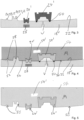
- Fig. 4 shows a part schematic sectional side view of the mold of Fig. 3 into which the removable material M has been introduced. Also visible is the hollow space 54'.
- Fig. 5 shows a sectional view similar to that of Fig. 4 , in which the removable material has solidified and the pattern 54 is removed from the mold 18.
- the inserts 24' are held at pre-defined positions within the pattern 54 at the outer surface 56.
- the pattern 54 further comprises recess 58 in the outer surface 56.
- the pattern 54 comprises two inserts 24, 24' placed at one or more predefined positions along the outer surface 56.
- the pattern 54 of removable material M can have a melting point selected in the temperature range of 80 to 130°C, preferably in the range of 95 to 120°C.
- the pattern 54 can remain stable in shape to temperatures selected in the range of 60 to 100°C, preferably in the range of 70 to 95°C.
- the pattern 54 of removable material M can remain stable in shape at temperatures below a melting point of said removable material M.
- Fig. 6 shows a sectional view similar to that of Fig. 5 , with the pattern 54 having been covered with layers of fiber material 60, 62.
- Woven layers of fiber material 60 are placed directly at the outer surface 56, whereas tows of fibers 62 have been inserted into the recess and the free spaces of the inserts accessible from the outer surface 56 of the pattern 54.
- the one or more layers of fiber material 60, 62 can comprise carbon fibers, glass fibers, basalt fibers, wood fibers, hemp fibers, aramid fibers, polyester fibers, in dry condition or as prepreg.
- the pattern 54 of removable material M can be used as a mold in resin transfer molding (RTM) processes to form composite devices in a manner known per se.
- Fig. 7 shows a sectional view similar to that of Fig. 6 , with the covered pattern 54 having been placed into a further mold 64.
- the further mold 64 has an internal surface 64'.
- the layers of fiber material 60, 62 are thus placed between the internal surface 64' of the further mold 64 and the outer surface 56 of the pattern 54.
- Fig. 8 shows a sectional view similar to that of Fig. 7 , with the space around the layers of fibers 60, 62 between the pattern 54 and the internal surface 64' of the further mold 64 filled with a resin R.
- the resin R is introduced from a reservoir 66 via a supply line 68.
- the further mold 64 can be heated to first, second and/or third temperatures in first, second and/or third temperature ranges via a heating and/or cooling device 96.
- the heating steps may be carried out gradually in a stepwise manner or continuously.
- the composite of fiber and resin is typically heated in steps to below the glass transition temperature of the resin in order to prevent the device to be formed from becoming soft and thereby obtaining a device with a deformed outer and/or inner surface.
- top half 18' of the mold 18, the bottom half 18" of the mold 18 and the further mold 64 are each preferably formed from a thermally conductive and non-magnetic material, such as aluminum or an aluminum alloy.
- the resin R is introduced into said further mold 64 during said step of heating of said further mold 64 to said first temperature.
- the resin R is heated to below a curing temperature of said resin R on the introduction of said resin R into said further mold 64.
- a vacuum V may be applied simultaneously via a vacuum pump 74 connected to a vacuum line 78 via a port 76.
- the resin R is cured in the further mold 64 to form the device 10.
- the step of curing comprises heating the further mold 64 to said second temperature.
- the second temperature is higher than the first temperature.
- the resin R at elevated temperature and which is possible pressurized is more flowable than unpressurized resin R at room temperature and hence can flow more easily through the roving and the further mold 64 in order to ensure, if possible, that no air pockets are formed in the composite material of the final device.
- the resin R is then permitted to solidify, i.e. harden, at a temperature selected below the melting temperature of the wax pattern 54, preferably while gradually increasing the temperature of the mold between the boundaries of the second temperature range from the lower temperature to the higher temperature, e.g. from 90°C to 100°C. If required, openings and/or apertures can be applied at the hardened composite device. Following which the temperature of the further mold 64 is gradually increased from e.g. 100°C to 120°C in order to melt out the wax pattern 54.
- the melting out of the wax pattern 54 can optionally also be carried out outside the mold 64, for example in an oven.
- the glass transition temperature of the resin can be increased temporaily in the mold during the stepwise gradual increase in temperature to above the melting point of the wax to form the device.
- the liquid wax can then be removed via the openings and/or apertures applied at the device 10.
- inserts 24' can be removed following the removal of the liquid wax in order to enable the placement of functional components at the position where a support therefore has been formed.
- an insert 24' forms a support for a bearing and the bearing 84 is then placed at the bearing support 12 inherently formed in the device 10.
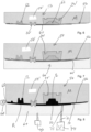
- Fig. 9 shows a sectional view similar to that of Fig. 8 , with the device 10 having been removed from the further mold 64. The removable material M of the pattern 54 is still present within the device 10.
- Fig. 10 shows a sectional view similar to that of Fig. 9 , with the pattern 54 having been removed from the device 10 due to the application of a heating step which heated the removable material M to above its melting point by heating the further mold 64 to the third temperature.
- Fig. 11 shows a sectional view similar to that of Fig. 10 , with the inserts 24' having been removed from the device 10.
- the left hand-insert in Fig. 10 was used to form an aperture 80 in the housing 16 of the device 10.
- the right-hand insert was used to form a support for a bearing, i.e. the bearing race can be assembled at the functional component 12 shown on the right in Fig. 11 .
- the left-hand functional component 12 is an internal seat for a component that can cooperate with the bearing seat.
- the device 10 of composite material thus comprises two functional components 12 placed at two predefined positions along the inner surface 14 of the device 10.
- the functional components 12 are integrally formed in one piece with said device 10.
- the device 10 can have a pre-definable wall thickness with a tolerance of the wall thickness lying in the range of ⁇ 0. 5 mm for a wall thickness selected in the range of 1 to 4 mm, in particular for a length of material of said device 10 cut from said device 10 in the range of 1 to 5 cm and at a width selected in the range of 0.5 to 2.5 cm.
- Fig. 12 shows a sectional view similar to that of Fig. 10 , with a seat 12 for a nut, i.e. a component having an internal thread inherently present at the inner surface 14 of the device 10.
- Fig. 13 shows a sectional view similar to that of Fig. 10 , with a T-shaped groove provided as the functional component 12 inherently present at the inner surface 14 of the device 10.
- Fig. 14 shows a sectional view similar to that of Fig. 10 , with the functional component 12' in the form of a threaded bolt is embedded within material of the device 10 at the inner surface 14 of the device 10.
- the threaded bolt has been bonded into place by means of the provision of an insert surrounding said bolt 12' which held the bolt 12' in place within the pattern and which enabled a permanent bond to be formed between the bolt 12' and the device 10 during the step of curing the resin R to form the device 10.
- the bolt 12' is in this way integrally embedded in one piece with the device 10.
- Fig. 15 shows a sectional view similar to that of Fig. 14 , with a sleeve 12' having an inner thread inherently present at the inner surface 14 of the device 10. Like with the bolt 12' of Fig. 14 , the sleeve 12' has been bonded to the device during the step of curing the resin R used to form the housing 16 of the device 10
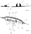
- Fig. 16 shows a schematic view of internal components of the device 10.
- the device 10 comprises a shaft 82 extending along the horizontal axis of said device 10. in which a ball bearing 84 is affixed to the device at a bearing support 12' which is integrally formed in one piece with the device 10.
- the shaft 82 is also journaled at the device 10 in a sleeve 86 and a sleeve 88.
- the shaft 82 is connected to an electric motor 94 via a transmission 92 and a drive shaft 90.
- the angular tolerance between the sleeve 86 and the ball bearing 84 is less than 0.1°, since the inserts 12 used for the two components were fixed relative to one another on forming the wax pattern 45. Angular tolerances of less than 0.05° are achievable by means of the present teaching. Moreover, an axial tolerance of positioning between the inserts 12 of the sleeve 86 and of the ball bearing 84 is less than 0.1 mm, preferably less than 0.05 mm. Similarly a tolerance of positioning between the inserts 12 of the sleeve 86 and of the ball bearing 84 is less than 0.05 mm + 0.5 mm/m, preferably less than 0.05 mm + 0.2 mm/m.
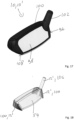
- Fig. 17 shows the device 10 to be a head of a golf club 96.
- the head 96 comprises a front face 98 and a body 100.
- the head can be connected to a shaft (not shown) via a shaft connector 102 in a manner known per se.
- two weights 104 can be provided as inserts 12' at the wax pattern 54.
- a further insert 12' is embedded within the wax pattern 54.
- This further insert 12' is a shaft connector insert 106 which permits an accurate connection of the shaft at a pre-defined angle to the front face and a base 108 of the golf club 10'. In this way the angle between the shaft of the golf club and the front face can be reliably formed with an improved alignment quality in comparison to the prior art.
- a method of forming a device (10) of composite material comprising the steps of:
- said step of holding comprises holding the inserts (24, 24') through the application of vacuum (V), the use of sliders (26), functional elements, and/or the use of magnets (28).
- said inserts (24, 24') comprise at least one of magnetic material and metal.
- said insert (24, 24') is shaped to form a functional component (12) or is a functional component (12') of said device (10).
- said pattern (54) of removable material (M) is produced in an injection molding process or a wax casting process.
- said removable material (M) is introduced into said cavity (20) in liquid form.
- said step of introducing said removable material (M) into said mold (18) comprises filling between 40 and 99% of said cavity (20) with liquid removable material (M).
- the method further comprises the step of: introducing gas (G) into said removable material (M) present in said mold (18) and pressurizing said removable material (M) present in said mold (18) with a pressure difference between an outside of said formed pattern (54) and a hollow space (54') within said pattern (54) selected in the range of 0.02 to 20 bar.
- the method further comprises the step of: applying a pressure selected in the range of 0.02 to 0.95 bar, in particular 0.05 to 0.5 bar in said cavity (20) prior to the introduction of the removable material (M) into said cavity.
- the method further comprises the step of: covering said pattern (54) having the inserts (24, 24') with one or more layers of one or more kinds of fiber material (60, 62).
- the method further comprises the step of: placing said pattern (54) having inserts (24, 24') and covered with said one or more layers of fiber material (60, 62) into a further mold (64).
- the method further comprises the step of: heating the further mold (64) to first, second and/or third temperatures in first, second and/or third temperature ranges.
- the method further comprises the step of: introducing a resin (R) into said further mold (64) prior to and/or during said step of heating of said further mold (64) to said first temperature optionally wherein a vacuum (V) is applied during said step of curing said resin (R).
- the method further comprises the step of: curing said resin (R) in said further mold (64) to form said device (10), wherein said step of curing comprises at least one of the application of heat and UV light.
- said step of the application of heat comprises heating said further mold (64) to said second temperature.
- said resin (R) is one of a one-component resin (R), a two-component resin (R) comprising a hardener, and a multi-component resin (R) comprising one or several hardeners.
- the resin (R) comprises a resin on an epoxy basis, a resin on a polyurethane basis, a resin on a cyanate ester or another basis suitable for injection or infusion.
- said one or more layers of fiber material (60, 62) comprise carbon fibers, glass fibers, basalt fibers, natural fibers, such as wood fibers and hemp fibers, aramid fibers, polyester fibers in dry condition or as prepreg.
- the method further comprises the step of: removing said removable material (M) from said device (10).
- the method further comprises the step of heating said further mold (64) to the third temperature.
- a pattern (54) of removable material (M) is provided, optionally obtainable by a method in accordance with one of the preceding embodiments, the pattern (54) comprising one or more inserts (24, 24') placed at one or more predefined positions along an outer surface (56) of said pattern (54).
- said pattern (54) of removable material (M) has a melting point selected in the temperature range of 80 to 140°C, preferably in the range of 95 to 130°C.
- said pattern (54) of removable material (M) remains stable in shape to temperatures selected in the range of 60 to 100°C, preferably in the range of 70 to 95°C.
- said pattern (54) of removable material (M) remains stable in shape at temperatures below a melting point of said removable material (M).
- said inserts (24, 24') comprise at least one of magnetic material and metal.
- said one or more inserts (24, 24') have a shape corresponding to a shape of one or more functional components (12) or are functional components (12') of a device (10).
- a device (10) of composite material is provided, optionally obtainable by a method in accordance with the invention, comprising one or more functional components (12, 12') placed at one or more predefined positions along an inner surface (14) of said device (10), with said functional components (12, 12') either being integrally formed in one piece with said device (10), or embedded within a structure integrally formed in one piece with said device (10).
- said functional component (12, 12') is selected from the group of members consisting of a tappet with an undercut, a pocket with an undercut, an internal seat (cylindrical), a bearing seat optionally with points of insertion for a circlip, a t-shaped groove (outwardly shaped and inwardly shaped), outer threads, such as bolts or studs with outer threads, inner threads such as sleeves with an inner thread or a nut, bayonet connections, open wedge sockets, eyelets, ball studs, dowels and dowel pins both optionally with points of insertion for a circlip, hooks, spring elements, bearing blocks, bearing blocks with clamping, saw tooth pins/ couplings with or without bores, sleeves, apertures, supports for one or more of the foregoing and combinations of the foregoing.
- said device (10) has a pre-definable wall thickness with a tolerance of the wall thickness lying in the range of ⁇ 0.5 mm, in particular of ⁇ 0.1 mm, especially of ⁇ 0.05 mm, for a wall thickness selected in the range of 1 to 4 mm, in particular for a length of material of said device (10) cut from said device (10) in the range of 1 to 5 cm and at a width selected in the range of 0.5 to 2.5 cm.
- said device (10) has a tolerance of the wall thickness lying in the range of ⁇ 0.3 mm, especially of ⁇ 0.2 mm, for a wall thickness selected in the range of 1 to 4 mm.
- said device (10) has a tolerance of the surface profile of ⁇ 0.1 mm.
- said device (10) has a tolerance of the surface profile of ⁇ 0.05 mm, in particular of ⁇ 0.03 mm, especially of ⁇ 0.01 mm at the position of the functional component (12) forming a second insert (24').
- two or more inserts are provided and an angular tolerance of positioning between the two inserts (12, 12') in said device (10) is less than 0.3°, preferably less than 0.2°, if the two or more inserts are fixed relative to one another in the pattern then the angular tolerance between the two inserts is less than 0.1°, preferably less than 0.05°.
- two or more inserts are provided and an axial tolerance of positioning between the inserts (12, 12') in said device (10) is less than 0.2 mm, preferably less than 0.1 mm, if two or more inserts are provided and are fixed relative to one another in the pattern then the axial tolerance between the two inserts is less than 0.1 mm, preferably less than 0.05 mm.
- two or more inserts are provided and a tolerance of positioning between the inserts at a spacing between the inserts in said device (10) is less than 0.1 mm + 1 mm/m, preferably less than 0.05 mm + 0.5 mm/m, if the two or more inserts are fixed relative to one another in the pattern then the positioning tolerance between the two inserts is less than 0.05 mm + 0.5 mm/m, preferably less than 0.05 mm + 0.2 mm/m.
- the device is a head (96) of a golf club (10') and the one or more functional components (12, 12') is selected as at least one of a weight (104) integrated into the golf club, a shaft connector insert (106) forming a connector to a shaft of the golf club (10'), and a surface acting as a face (98) of the golf club (10').
- one or more functional components are provided that act as one or more weights (104) of the head, one functional component is provided that acts as the shaft connector insert (106) and one functional component is provided that acts as the face (98) of the head (96) of the golf club (10').
Landscapes
- Engineering & Computer Science (AREA)
- Mechanical Engineering (AREA)
- Chemical & Material Sciences (AREA)
- Composite Materials (AREA)
- Physics & Mathematics (AREA)
- Health & Medical Sciences (AREA)
- Oral & Maxillofacial Surgery (AREA)
- Thermal Sciences (AREA)
- Electromagnetism (AREA)
- Manufacturing & Machinery (AREA)
- Power Engineering (AREA)
- Toxicology (AREA)
- Moulds For Moulding Plastics Or The Like (AREA)
- Injection Moulding Of Plastics Or The Like (AREA)
- Golf Clubs (AREA)
- Reinforced Plastic Materials (AREA)
- Laminated Bodies (AREA)
- Manufacturing Of Printed Wiring (AREA)
Priority Applications (1)
| Application Number | Priority Date | Filing Date | Title |
|---|---|---|---|
| EP24210461.0A EP4477395A3 (de) | 2019-09-19 | 2019-09-19 | Verfahren zur herstellung einer vorrichtung aus verbundmaterial, muster, vorrichtung |
Applications Claiming Priority (3)
| Application Number | Priority Date | Filing Date | Title |
|---|---|---|---|
| PCT/EP2019/075253 WO2021052596A1 (en) | 2019-09-19 | 2019-09-19 | Method of forming a device of composite material, a pattern, a device |
| EP19773069.0A EP4003682A1 (de) | 2019-09-19 | 2019-09-19 | Verfahren zur herstellung einer vorrichtung aus verbundstoff, muster, vorrichtung |
| EP24210461.0A EP4477395A3 (de) | 2019-09-19 | 2019-09-19 | Verfahren zur herstellung einer vorrichtung aus verbundmaterial, muster, vorrichtung |
Related Parent Applications (1)
| Application Number | Title | Priority Date | Filing Date |
|---|---|---|---|
| EP19773069.0A Division EP4003682A1 (de) | 2019-09-19 | 2019-09-19 | Verfahren zur herstellung einer vorrichtung aus verbundstoff, muster, vorrichtung |
Publications (2)
| Publication Number | Publication Date |
|---|---|
| EP4477395A2 true EP4477395A2 (de) | 2024-12-18 |
| EP4477395A3 EP4477395A3 (de) | 2025-02-26 |
Family
ID=67999667
Family Applications (2)
| Application Number | Title | Priority Date | Filing Date |
|---|---|---|---|
| EP19773069.0A Pending EP4003682A1 (de) | 2019-09-19 | 2019-09-19 | Verfahren zur herstellung einer vorrichtung aus verbundstoff, muster, vorrichtung |
| EP24210461.0A Pending EP4477395A3 (de) | 2019-09-19 | 2019-09-19 | Verfahren zur herstellung einer vorrichtung aus verbundmaterial, muster, vorrichtung |
Family Applications Before (1)
| Application Number | Title | Priority Date | Filing Date |
|---|---|---|---|
| EP19773069.0A Pending EP4003682A1 (de) | 2019-09-19 | 2019-09-19 | Verfahren zur herstellung einer vorrichtung aus verbundstoff, muster, vorrichtung |
Country Status (8)
| Country | Link |
|---|---|
| US (1) | US20220339894A1 (de) |
| EP (2) | EP4003682A1 (de) |
| JP (3) | JP7444976B2 (de) |
| KR (1) | KR20220064386A (de) |
| CN (1) | CN114423578A (de) |
| AU (1) | AU2019466407B2 (de) |
| CA (1) | CA3150198A1 (de) |
| WO (1) | WO2021052596A1 (de) |
Families Citing this family (4)
| Publication number | Priority date | Publication date | Assignee | Title |
|---|---|---|---|---|
| KR20220064386A (ko) * | 2019-09-19 | 2022-05-18 | 어덜티멈 아게 | 복합 재료의 장치를 형성하는 방법, 패턴, 장치 |
| DE102022110187A1 (de) | 2022-04-27 | 2023-11-02 | Ucosan B.V. | Einlagevorrichtung, Vorrichtung und Verfahren zur Herstellung eines Gussteils |
| FR3146088B1 (fr) * | 2023-02-28 | 2026-01-02 | Safran Nacelles | Noyau de moulage |
| CN120439590A (zh) * | 2025-06-17 | 2025-08-08 | 广东众森实业发展有限公司 | 一种车用碳纤维前唇结构及其加工工艺 |
Family Cites Families (27)
| Publication number | Priority date | Publication date | Assignee | Title |
|---|---|---|---|---|
| GB704324A (en) * | 1950-05-20 | 1954-02-17 | Birmingham Small Arms Co Ltd | Improvements in or relating to machines for injecting molten materials into a mould or die |
| US3063113A (en) * | 1959-12-10 | 1962-11-13 | Howe Sound Co | Disposable pattern with lower melting external coating |
| GB1037527A (en) * | 1963-09-24 | 1966-07-27 | Rolls Royce | Improvements in or relating to dies or moulds |
| US4023257A (en) * | 1976-01-21 | 1977-05-17 | Nl Industries, Inc. | Method of making a hollow article having a reinforced aperture |
| GB2015923A (en) * | 1978-03-09 | 1979-09-19 | Trevelyans Birmingham Ltd | Manufacturing Tanks and other Hollow Articles |
| US4420156A (en) * | 1982-03-22 | 1983-12-13 | Pepsico, Inc. | Iron-type golf clubs |
| JPS59198127A (ja) * | 1983-04-27 | 1984-11-09 | M C L:Kk | ワックス模型の射出成形方法 |
| FR2703255A1 (fr) * | 1993-03-29 | 1994-10-07 | Ozen Sa | Corps creux, tel qu'une tête de club de golf, en matière thermoplastique moulée, comportant un insert emprisonné, et son procédé de fabrication. |
| US5441680B1 (en) * | 1994-05-02 | 1997-04-29 | Milko G Guergov | Method and apparatus for injection molding |
| US5651932A (en) * | 1995-04-14 | 1997-07-29 | Butler; Byron | Method for investment wax casting of golf club heads |
| JPH08322971A (ja) * | 1995-06-01 | 1996-12-10 | Fuoot-N:Kk | 複合素材から成るゴルフクラブのクラブヘッド及びその製造方法 |
| JP3572772B2 (ja) * | 1995-12-29 | 2004-10-06 | ソニー株式会社 | 半導体封止用金型装置及びこの金型装置を用いた半導体封止装置並びに半導体装置の封装樹脂成形方法 |
| EP1197309B1 (de) * | 2000-10-04 | 2004-04-07 | Alcan Technology & Management AG | Verfahren zur Herstellung von Bauteilen aus Faserverbundkunststoffen |
| JP2003024483A (ja) * | 2001-06-08 | 2003-01-28 | Callaway Golf Co | 複合ゴルフクラブヘッド及びその製造方法 |
| JP2003291208A (ja) * | 2002-04-04 | 2003-10-14 | Toyota Motor Corp | 樹脂中空成形品の製造方法 |
| JP3099571U (ja) | 2003-07-30 | 2004-04-08 | 大田精密工業股▲ふん▼有限公司 | ゴルフクラブヘッド |
| EP1707287A1 (de) * | 2004-01-23 | 2006-10-04 | Shonan Design Co., Ltd. | Verfahren zur herstellung eines harzmodells und verfahren zum wachsausschmelz-präzisionsgiessen mit dem harzmodell |
| JP5354250B2 (ja) | 2008-03-31 | 2013-11-27 | ミズノ テクニクス株式会社 | シャフト取付け用スペーサー |
| DE102009034724A1 (de) * | 2009-07-24 | 2011-02-03 | Daimler Ag | Verfahren zur Herstellung eines Bauteils |
| US9259625B2 (en) * | 2009-12-23 | 2016-02-16 | Taylor Made Golf Company, Inc. | Golf club head |
| KR101328453B1 (ko) | 2012-04-17 | 2013-11-14 | 삼익정공(주) | 피치자동조정용 링크부재, 링크부재 제조방법 및 피치자동조정용 엑스 바 부품세트 |
| US10137335B2 (en) * | 2015-11-09 | 2018-11-27 | Karsten Manufacturing Corporation | Embedded high density casting |
| CN107206471B (zh) * | 2015-11-11 | 2018-11-13 | 荣进科技有限公司 | 蜡模注射成型装置和使用蜡模注射成型装置的物品的铸造方法 |
| WO2017127303A1 (en) | 2016-01-21 | 2017-07-27 | Parsons Xtreme Golf, LLC | Golf club heads and methods to manufacture golf club heads |
| US20170282415A1 (en) * | 2016-03-14 | 2017-10-05 | Ripple Engineering LLC | Rotational molding system |
| IT201600105326A1 (it) * | 2016-10-19 | 2018-04-19 | Cannon Spa | Metodo ed apparato per produrre un corpo cavo chiuso in materiale composito |
| KR20220064386A (ko) * | 2019-09-19 | 2022-05-18 | 어덜티멈 아게 | 복합 재료의 장치를 형성하는 방법, 패턴, 장치 |
-
2019
- 2019-09-19 KR KR1020227011994A patent/KR20220064386A/ko active Pending
- 2019-09-19 AU AU2019466407A patent/AU2019466407B2/en active Active
- 2019-09-19 EP EP19773069.0A patent/EP4003682A1/de active Pending
- 2019-09-19 US US17/761,470 patent/US20220339894A1/en active Pending
- 2019-09-19 CN CN201980100351.0A patent/CN114423578A/zh active Pending
- 2019-09-19 WO PCT/EP2019/075253 patent/WO2021052596A1/en not_active Ceased
- 2019-09-19 JP JP2022518404A patent/JP7444976B2/ja active Active
- 2019-09-19 CA CA3150198A patent/CA3150198A1/en active Pending
- 2019-09-19 EP EP24210461.0A patent/EP4477395A3/de active Pending
-
2024
- 2024-02-21 JP JP2024024263A patent/JP7839210B2/ja active Active
- 2024-02-21 JP JP2024024260A patent/JP7652955B2/ja active Active
Also Published As
| Publication number | Publication date |
|---|---|
| WO2021052596A1 (en) | 2021-03-25 |
| JP2022552623A (ja) | 2022-12-19 |
| CA3150198A1 (en) | 2021-03-25 |
| JP7839210B2 (ja) | 2026-04-01 |
| JP7652955B2 (ja) | 2025-03-27 |
| JP2024045675A (ja) | 2024-04-02 |
| EP4003682A1 (de) | 2022-06-01 |
| US20220339894A1 (en) | 2022-10-27 |
| JP7444976B2 (ja) | 2024-03-06 |
| AU2019466407B2 (en) | 2025-10-02 |
| CN114423578A (zh) | 2022-04-29 |
| KR20220064386A (ko) | 2022-05-18 |
| EP4477395A3 (de) | 2025-02-26 |
| JP2024045676A (ja) | 2024-04-02 |
| AU2019466407A1 (en) | 2022-03-24 |
Similar Documents
| Publication | Publication Date | Title |
|---|---|---|
| JP7652955B2 (ja) | 複合材料のデバイスを形成する方法、パターン、デバイス | |
| EP4003752B1 (de) | Verfahren zum zusammenbauen einer fahrradfelge | |
| US5260014A (en) | Method of making a multilayer injection mold | |
| US5944087A (en) | Process for producing the mold inserts for injection moldings | |
| US7125512B2 (en) | Rapid prototype injection molding | |
| CN107745749A (zh) | 复合材料汽车引擎盖及其制备方法 | |
| DE102007015389B4 (de) | Bauteil und Verfahren zu dessen Herstellung | |
| US20160167117A1 (en) | Salt core and additive manufacturing method for producing salt cores | |
| EP4003622A1 (de) | Verfahren zur herstellung eines wachsmodells, wachsmodell | |
| CN107096882B (zh) | 基于3d打印的铸造用模具及该模具的制备方法 | |
| US5296183A (en) | Method for comolding property enhancing coatings to composite articles | |
| TWI294801B (en) | Article casting method | |
| US20100015265A1 (en) | Pressure bladder and method for fabrication | |
| US20150102523A1 (en) | Consecutive piecewise molding system and method | |
| US5385421A (en) | Fail-safe composite-cast metal structure | |
| JPH0839574A (ja) | 中空プラスチック品の製造方法 | |
| US20100055410A1 (en) | Molding article with reinforced passages | |
| IT201600105326A1 (it) | Metodo ed apparato per produrre un corpo cavo chiuso in materiale composito | |
| TW202202317A (zh) | 用於製造部件之工具總成及生產工具總成之方法 | |
| KR20130022949A (ko) | 폴리머 수지와 금속의 복합재료를 이용한 용사금형의 제조방법 | |
| TR2025017115A2 (tr) | Üç Boyutlu Kum Yazıcı ile Üretilen Maçaların Döküm Esnasında Hareketini Engelleyen Bir Yöntem | |
| JPS63267519A (ja) | 樹脂型の製造法 | |
| JPWO1995017298A1 (ja) | 硬質ロールの製造法 | |
| Weatherhead | Moulds |
Legal Events
| Date | Code | Title | Description |
|---|---|---|---|
| PUAI | Public reference made under article 153(3) epc to a published international application that has entered the european phase |
Free format text: ORIGINAL CODE: 0009012 |
|
| STAA | Information on the status of an ep patent application or granted ep patent |
Free format text: STATUS: THE APPLICATION HAS BEEN PUBLISHED |
|
| AC | Divisional application: reference to earlier application |
Ref document number: 4003682 Country of ref document: EP Kind code of ref document: P |
|
| AK | Designated contracting states |
Kind code of ref document: A2 Designated state(s): AL AT BE BG CH CY CZ DE DK EE ES FI FR GB GR HR HU IE IS IT LI LT LU LV MC MK MT NL NO PL PT RO RS SE SI SK SM TR |
|
| REG | Reference to a national code |
Ref country code: DE Ref legal event code: R079 Free format text: PREVIOUS MAIN CLASS: B29K0091000000 Ipc: B29C0033520000 |
|
| PUAL | Search report despatched |
Free format text: ORIGINAL CODE: 0009013 |
|
| AK | Designated contracting states |
Kind code of ref document: A3 Designated state(s): AL AT BE BG CH CY CZ DE DK EE ES FI FR GB GR HR HU IE IS IT LI LT LU LV MC MK MT NL NO PL PT RO RS SE SI SK SM TR |
|
| RIC1 | Information provided on ipc code assigned before grant |
Ipc: B29K 91/00 20060101ALN20250120BHEP Ipc: B29C 45/00 20060101ALN20250120BHEP Ipc: B29C 39/42 20060101ALN20250120BHEP Ipc: B29C 33/44 20060101ALI20250120BHEP Ipc: B29C 33/42 20060101ALI20250120BHEP Ipc: B29C 33/38 20060101ALI20250120BHEP Ipc: B29C 67/24 20060101ALI20250120BHEP Ipc: B29C 70/86 20060101ALI20250120BHEP Ipc: B29C 39/34 20060101ALI20250120BHEP Ipc: B29C 39/10 20060101ALI20250120BHEP Ipc: B29C 70/48 20060101ALI20250120BHEP Ipc: B29C 33/52 20060101AFI20250120BHEP |
|
| STAA | Information on the status of an ep patent application or granted ep patent |
Free format text: STATUS: REQUEST FOR EXAMINATION WAS MADE |