EP4477608A1 - Dispositif de suspension de charge pour fixer une balustrade à un dispositif de voie - Google Patents
Dispositif de suspension de charge pour fixer une balustrade à un dispositif de voie Download PDFInfo
- Publication number
- EP4477608A1 EP4477608A1 EP23178915.7A EP23178915A EP4477608A1 EP 4477608 A1 EP4477608 A1 EP 4477608A1 EP 23178915 A EP23178915 A EP 23178915A EP 4477608 A1 EP4477608 A1 EP 4477608A1
- Authority
- EP
- European Patent Office
- Prior art keywords
- load
- bearing device
- adapter element
- profile
- receiving element
- Prior art date
- Legal status (The legal status is an assumption and is not a legal conclusion. Google has not performed a legal analysis and makes no representation as to the accuracy of the status listed.)
- Pending
Links
Images

Classifications
-
- B—PERFORMING OPERATIONS; TRANSPORTING
- B66—HOISTING; LIFTING; HAULING
- B66B—ELEVATORS; ESCALATORS OR MOVING WALKWAYS
- B66B23/00—Component parts of escalators or moving walkways
- B66B23/22—Balustrades
Definitions
- the present invention relates to a load-bearing device for supporting a load on a profile, in particular on an upper chord of a supporting structure of a guideway device.
- the invention further relates to an adapter element and a receiving element of such a load-bearing device, a supporting structure with such a load-bearing device and a guideway device with such a supporting structure.
- Balustrades are usually held on load-bearing devices that are arranged on an upper chord of the side wall unit(s) and serve as fall protection for passengers on the travel path device and/or to limit the travel path area to the sides.
- Such balustrades and associated load-bearing devices are designed to support the load of several passengers who press or fall against the upper end of the balustrade with their body weight.
- the disadvantage is that load-bearing devices for meeting these design requirements are often very large and heavy and take up a relatively large amount of the limited space available on the supporting structure.
- load-bearing devices are often complex to install and/or complex to align for a desired positioning of the balustrade panels.
- the object is accordingly achieved by a load-bearing device for receiving a load on a profile, in particular on an upper chord of a support structure of a guideway device, the load-bearing device having an adapter element with a first leg assigned to a first side of the profile and a second leg assigned to a second side of the profile and a receiving element, wherein the adapter element has a first projection on the first leg for positioning the adapter element on a first recess of the profile and a second projection on the second leg for positioning the adapter element on a second recess of the profile, wherein the receiving element can be connected or is connected to the first leg of the adapter element at a first connection point and to the second leg of the adapter element at a second connection point, and wherein a load receiver is formed on the receiving element.
- guideway device refers primarily to escalator devices and moving walkway devices (the latter in particular in a stepless design in an at least approximately flat alignment or with a negligible gradient) as well as related passenger transport devices with a continuously rotating transport device.
- a guideway device comprises, for example, steps or pallets forming the transport device, which are connected to driven drive means and guided in guides.
- the guides as well as the drive means and other components of the guideway device are usually held within support structures extending longitudinally essentially laterally therefrom, which are usually formed from two side wall units lying opposite one another and connected to one another via crossbeams and optionally also a floor unit.
- guideway device also refers in particular to modularly constructed guideway devices which are modularly constructed from several longitudinal sections or longitudinal section modules, each with an individual or individually created support structure, and which can be assembled/mounted in modules.
- the supporting structure of the guideway device or the respective module is preferably formed essentially by opposing side wall units and cross beams connecting them (also referred to as crossbars), whereby a respective side wall unit is formed by at least one side wall and in particular by an upper chord and/or a lower chord.
- a supporting structure can also comprise a floor unit; however, it has been shown that such a floor unit does not necessarily have to fulfil a supporting function, but can, for example, be used with regard to the Function is designed to collect oil from a drive and drain it away if necessary, or is designed to be optimized with regard to coverage and/or accessibility from below to the support structure or the guideway device.
- the floor unit is to be understood as an optional structural unit which can also be functionally provided separately from the support structure, but which can optionally also take on an additional supporting load-bearing function if desired in individual cases.
- side wall refers to a side structure of the supporting structure, which, for example, runs flat in only one side plane at least in sections and/or is formed and/or reinforced at least in sections by profiles, struts or supports that extend beyond the side plane.
- the side wall is made up of structural elements or structural sections that, as flat structural sections, absorb forces in several directions and/or, as rod-shaped or strut-like structural elements/sections, absorb the respective forces only along the longitudinal extension specified by the orientation.
- the side wall is therefore designed, for example, as a closed surface, as a pure framework or as a structure with parts of closed surfaces and parts with a framework structure.
- a side wall unit comprises the side wall described above and belts assigned to this side wall as further structural elements/sections, in particular an upper belt and a lower belt, wherein the belts can be formed in one piece with the side wall, integrated or separate from one another.
- the belts are preferably designed as profiles or profile sections, in particular as L-profiles, U-profiles or hollow profiles and thus have a favorable area moment of inertia for absorbing the bending loads.
- the belts therefore stiffen the support structure and form outer corner points, wherein optionally the belts and/or the Side walls serve to attach further components of the guideway device.
- the belts can also be designed as components separate from the side wall; however, at least some of the belts are preferably formed in one piece with the side wall, for example by bending the side wall.
- the upper belt is particularly preferably designed as a hollow profile with four walls, with two walls being formed, for example, by the L-shaped side wall made from flat material in this area and two further walls being formed by a flat material component that is also L-shaped and separate from the side wall.
- the lower belt is also preferably designed in a similar way as a hollow profile with four walls. The components forming the walls are preferably welded together.
- a load-bearing device comprises means for the load-resistant transfer of a force or a moment from the load to a profile, in particular a profile of the supporting structure that absorbs the force or the moment.
- the load is a force acting on an attachment such as a balustrade or a corresponding moment that is diverted to the profile via the load-bearing device.
- the load-bearing device is therefore intended to be attached to the element of the supporting structure (in particular the upper chord) in a load-resistant manner on the one hand and to have a load holder in which the load can be or is held in a load-resistant manner on the other.
- Load-resistant is understood to mean that forces and moments can be transferred safely via the connection(s) at least in the directions relevant for a normal load case, in particular without material damage or failure.
- the respective projection and the respective recess form a positive connection with each other, by which the positioning of the adapter element on the profile is determined.
- the adapter element or the projection and/or the profile or the recess is manufactured using a high-precision manufacturing process, such as laser cutting or water cutting, so that the load-bearing device is already aligned by the positioning.
- the first and second projections are each designed to engage in a slot-shaped recess.
- connection to the profile is formed by the adapter element, whereby the adapter element is positioned on two sides of the profile and can then be connected to the profile on both sides, for example by welding.
- the connection between the adapter element and the profile can also be made particularly conveniently before the receiving element is connected to the adapter element, so that, for example, welding points are particularly easy to access.
- the solution to the problem using the load-bearing device includes the teaching that the receiving element is connected to the adapter element on both legs and in turn forms the load-bearing device.
- the load transfer between the load-bearing device and the profile is therefore realized via both sides or both legs and the load-bearing device is therefore mechanically designed to be particularly favorable, in particular for absorbing moments.
- the attachment points of the legs of the adapter element on the respective sides of the profile can be spaced relatively far apart from one another to absorb high moments. This advantageous design allows the adapter element and the receiving element to be made particularly small and light.
- the adapter element can itself be designed to be particularly rigid in a plane perpendicular to the axial direction of the profile (around which a moment load mainly occurs) in order to transmit forces and/or moments in this plane, while only the receiving element also has a greater extension in the axial direction in order to form the load support for a load extending in the axial direction, such as a balustrade of a guideway device.
- the adapter element can then be designed to be particularly compact and light.
- the adapter element is L-shaped and made of a flat material and extends in a plane perpendicular to the axial direction of the profile.
- the adapter element is made of a metal sheet.
- the adapter element is then particularly light and at the same time particularly load-resistant in the plane perpendicular to the axial direction of the profile, in which the greatest forces/moments are to be expected as a load, for example in the case of a balustrade of a guideway device.
- the L-shaped design in which the first leg and the second leg are materially connected, further increases the ability of the adapter element to transmit forces or moments.
- first connection point and/or the second connection point are each formed by a first through-opening on the adapter element, a second through-opening on the receiving element and a fastening means that passes through the first through-opening and the second through-opening.
- the fastening means is in particular a screw that interacts with a nut.
- a frictional connection is then created between the receiving element and the adapter element, which is designed to be particularly load-resistant, in particular for the transmission of forces and moments in the plane perpendicular to the axial direction of the profile.
- the alignment of the through-openings with one another ensured by the fastening means, enables highly precise positioning of the receiving element with respect to the adapter element, so that the load absorption through the aligned through-openings and the above-described highly precise positioning of the adapter element on the profile is aligned particularly precisely with respect to the profile by the recesses and projections.
- the receiving element can be attached to the adapter element equally from a first side or a second side, so that for the mirror-inverted arrangement of load-bearing devices on two opposite upper chords, identical parts can advantageously be used.
- the receiving element can encompass the adapter element, wherein the receiving element is mirror-symmetrical with respect to the plane formed by the adapter element, so that for the mirror-inverted arrangement of For load-bearing devices on two opposite upper chords, identical parts can advantageously be used.
- a first through-opening is preferably designed as an arcuate elongated hole, in particular, the elongated hole extending along a radius around a rotation axis of a second first through-opening.
- an extension along the radius is understood to mean that the radius lies on a central axis of the elongated hole.
- an extension along the radius is understood to mean, for example, that the central axis of the elongated hole lies tangentially to the radius.
- the receiving element can advantageously be rotated in an angular range determined by the elongated hole around the rotation axis of the second first through-opening before the fastening means are tightened or otherwise closed in order to precisely align the load-bearing element, for example relative to other load-bearing elements of other load-bearing devices provided on the same profile.
- the load-bearing device is designed as a U-shaped clamping device, in particular for holding a balustrade panel of a guideway device.
- the clamping device is then open in particular at the top and carries a balustrade panel such as a glass panel downwards against gravity and inwards and outwards when the balustrade is subjected to a moment load, for example by a person leaning against the balustrade or falling against it.
- the balustrade is therefore held securely in all relevant directions and can also be easily mounted in the load-bearing device from above.
- a sealing element and/or a shape compensation element such as a rubber profile or a paper seal can also be inserted into the U-shaped clamping device.
- the clamping device particularly preferably has a movable clamping element, wherein a load received in the load holder can be clamped by moving the clamping element.
- the load in particular a balustrade panel
- the clamping element can then be inserted into the clamping device from the open side of the clamping device, in particular from above, without any great resistance. and then secured by the clamping element, in particular after aligning the receiving element relative to receiving elements of other load-bearing devices in which the balustrade panel or other balustrade panels of the same balustrade are inserted.
- the clamping element is designed to be movable against the receiving element by means of a screw.
- the clamping device can then be closed particularly easily by tightening the screw and the assembly of the load-bearing device is therefore particularly simple.
- the screw is particularly preferably designed as a hammer head screw, wherein the screw passes through the receiving element so that a hammer head of the screw is held on a side of the receiving element facing the adapter element.
- the screw is thus held on the adapter element even when the clamping device is open, i.e. without the clamping element pressing on a load and thus causing the screw to self-lock, and can therefore be pre-assembled before the load-bearing device is assembled.
- the screw does not first have to be arranged on the load-bearing device, but only tightened. The assembly of the load is thus further simplified.
- the screw particularly preferably acts on a pivoting element, the pivoting element being able to be pivoted about a contact point on the receiving element by means of the screw in order to move the clamping element.
- the pivoting element therefore rests on the one hand on the contact point on the receiving element and on the other hand on a contact point on the clamping element in order to be pivoted about the contact point on the receiving element when the screw is tightened and to act on the clamping element.
- the screw can then be locked on the receiving element away from the load bearing element so that mechanical weakening of the receiving element is prevented by providing a hole in the area of the load bearing element.
- a lever arm between the contact point on the receiving element and the contact point on the clamping element can generate a particularly high and precisely controlled clamping force through the clamping element.
- the object is further achieved by an adapter element for a load-bearing device described above.
- the adapter element can be used to achieve the advantages described above with regard to the load-bearing device in a corresponding manner.
- the object is further achieved by a receiving element for a load-bearing device as described above.
- the advantages described above with regard to the load-bearing device can be achieved in a corresponding manner using the receiving element.
- a support structure for a guideway device having at least one side wall unit with at least one upper flange and one side wall, wherein a load-bearing device as described above is arranged, in particular welded, on the upper flange, and wherein the upper flange receives the first projection of the adapter element at a first recess on a first side and receives the second projection of the adapter element at a second recess on a second side.
- the adapter element is welded to the upper flange along the recesses or projections.
- first recess and the second recess are designed in a slot-shaped manner, for example by means of laser cutting or water jet cutting, in order to enable precise and spatially defined positioning of the projections.
- the upper flange is designed as a rectangular hollow profile and the first side is an upper side of the upper flange and the second side is a side of the upper flange facing an inner side of the support structure.
- a hollow profile is understood to be a profile that has at least one area in cross-section that is essentially enclosed by walls. In this area of the cross-section, at least two walls are located opposite each other, so that the accessibility of a respective wall is restricted from the side facing the other wall.
- a guideway device in particular an escalator device, having a support structure as described above.
- the advantages described above with regard to the support structure or the advantages described above with regard to the load-bearing device can be achieved in a corresponding manner with the guideway device.
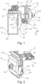
- Figure 1 shows a side view of a load-bearing device 1, which is arranged on an upper flange 2 of a support structure (not shown in detail) of a guideway device (also not shown in detail).
- the load-bearing device 1 is formed by an adapter element 3 and a receiving element 4 with a load-bearing device 5 arranged thereon.
- the upper flange 2 is formed by a first side 2.1 formed as an upper wall, a second side 2.2 formed as an inner wall, a third side 2.3 formed as an outer wall and a fourth side 2.4 formed as a lower wall.
- the second wall 2.2 is therefore facing the steps or pallets of the guideway device (not shown).
- the adapter element 3 is made of a metal sheet in an L-shape with a first leg 3.1 and a second leg 3.2, wherein the adapter element 3 extends in a plane spanned by a transverse direction Q and a vertical direction H, which is perpendicular to an axial direction A of the upper flange 2.
- the axial direction A is, for example, in Figure 2 shown.
- the first leg 3.1 is assigned to the first side 2.1 of the upper chord 2, i.e. it rests against this, and the second leg 3.2 is assigned to the second side 2.2 of the upper chord 2, i.e. it rests against this.
- a first projection 6.1 is formed on the first leg 3.1, which engages in a slot-shaped recess on the first side 2.1 of the upper chord 2 for positioning the load-bearing device 1 on the upper chord 2.
- a second projection 6.2 is formed on the second leg 3.2, which engages in a further slot-shaped recess on the second side 2.2 of the upper chord 2 for positioning the load-bearing device 1 on the upper chord 2.
- the adapter element 3 is welded to the upper chord 2 in the region of the first projection 6.1 and the second projection 6.2 via weld seams 7.1, 7.2.
- Figure 4 shows the adapter element 3 isolated, whereby the position of the first projection 6.1 differs slightly from the illustration in Figure 1 As in Figure 4
- a first through-opening 8.1 and a second through-opening 8.2 are also formed on the adapter element 3.
- the first through-opening 8.1 is designed as an arcuate elongated hole, a central axis M of the first through-opening 8.1 thus runs along a radius R around a rotation axis AX (in Figure 2 shown) of the second first through opening 8.2.
- the receiving element 4 is attached to the adapter element 3 via a first connection point 9.1 and a second connection point 9.2.
- the first connection point 9.1 is connected to the first through-opening 8.1 of the adapter element 3, a first second through-opening 10.1 of the Figure 3 in section shown receiving element 4 and a first fastening means 11.1 designed as a screw, which passes through the first first through-opening 8.1 and the first second through-opening 10.1.
- the second connection point 9.2 is formed by the second first through-opening 8.2 of the adapter element 3, a second second through-opening 10.2 of the Figure 3 receiving element 4 shown in section and a second fastening means 11.2 designed as a screw that passes through the second first through-opening 8.2 and the second second through-opening 10.2.
- the receiving element 4 can be tilted relative to the adapter element 3 about the rotation axis AX of the first connection point 9.2, as far as the first through-opening 8.1 allows this, in order to adjust the load bearing device 5.
- An outer flank 5.3 is formed by a clamping element 12, which is movably arranged on the receiving element 4. Sealing elements/shape compensation elements are also provided on the inside of the flanks 5.1, 5.2, 5.3 in order to be able to securely accommodate, for example, a balustrade panel made of glass in the load support 5.
- a swivel element 13 acts on the clamping element 12, which rests on a fixed part of the receiving element 4 at a first contact point 14.1 and rests on the clamping element 12 at a second contact point 14.2 in order to move the latter.
- the swivel element 13 is movable against the receiving element 4 by means of a screw 15 designed as a hammer head screw in order to be swiveled about the first contact point 14.1 and thereby act on the clamping element 12 at the second contact point 14.2.
- the screw 15 for this purpose passes through a Figure 3 through opening 16 shown in more detail, in which a pocket 16.1 is formed.
- a thread (not shown in more detail) is provided against which the screw 15 is held, wherein a hammer head 15.1 of the screw 15 is also held on the back of the pocket 16.1, so that the screw 15 is held captive and thus pre-assembled on the receiving element 4.
Landscapes
- Escalators And Moving Walkways (AREA)
Priority Applications (3)
| Application Number | Priority Date | Filing Date | Title |
|---|---|---|---|
| EP23178915.7A EP4477608A1 (fr) | 2023-06-13 | 2023-06-13 | Dispositif de suspension de charge pour fixer une balustrade à un dispositif de voie |
| CN202480038615.5A CN121285523A (zh) | 2023-06-13 | 2024-03-14 | 用于将扶栏固定在行驶路径装置上的载荷承载装置 |
| PCT/EP2024/056800 WO2024256045A1 (fr) | 2023-06-13 | 2024-03-14 | Dispositif de transport de charge pour fixer une balustrade à un dispositif de guidage |
Applications Claiming Priority (1)
| Application Number | Priority Date | Filing Date | Title |
|---|---|---|---|
| EP23178915.7A EP4477608A1 (fr) | 2023-06-13 | 2023-06-13 | Dispositif de suspension de charge pour fixer une balustrade à un dispositif de voie |
Publications (1)
| Publication Number | Publication Date |
|---|---|
| EP4477608A1 true EP4477608A1 (fr) | 2024-12-18 |
Family
ID=86764861
Family Applications (1)
| Application Number | Title | Priority Date | Filing Date |
|---|---|---|---|
| EP23178915.7A Pending EP4477608A1 (fr) | 2023-06-13 | 2023-06-13 | Dispositif de suspension de charge pour fixer une balustrade à un dispositif de voie |
Country Status (3)
| Country | Link |
|---|---|
| EP (1) | EP4477608A1 (fr) |
| CN (1) | CN121285523A (fr) |
| WO (1) | WO2024256045A1 (fr) |
Citations (5)
| Publication number | Priority date | Publication date | Assignee | Title |
|---|---|---|---|---|
| US5156251A (en) * | 1992-04-07 | 1992-10-20 | Otis Elevator Company | Balustrade mounting assembly for escalator or moving walkway |
| DE202008014640U1 (de) * | 2008-11-04 | 2009-01-22 | Thyssenkrupp Fahrtreppen Gmbh | Fahrtreppe oder Fahrsteig |
| US9944496B2 (en) * | 2014-04-30 | 2018-04-17 | Inventio Ag | Track system for an escalator or a moving walkway |
| US10954070B1 (en) * | 2019-10-14 | 2021-03-23 | Intelligrated Headquarters, Llc | Conveyor with a stanchion for mounting an equipment on the conveyor |
| WO2022200029A1 (fr) * | 2021-03-26 | 2022-09-29 | Inventio Ag | Structure de support d'un escalier roulant ou d'un trottoir roulant |
-
2023
- 2023-06-13 EP EP23178915.7A patent/EP4477608A1/fr active Pending
-
2024
- 2024-03-14 WO PCT/EP2024/056800 patent/WO2024256045A1/fr not_active Ceased
- 2024-03-14 CN CN202480038615.5A patent/CN121285523A/zh active Pending
Patent Citations (5)
| Publication number | Priority date | Publication date | Assignee | Title |
|---|---|---|---|---|
| US5156251A (en) * | 1992-04-07 | 1992-10-20 | Otis Elevator Company | Balustrade mounting assembly for escalator or moving walkway |
| DE202008014640U1 (de) * | 2008-11-04 | 2009-01-22 | Thyssenkrupp Fahrtreppen Gmbh | Fahrtreppe oder Fahrsteig |
| US9944496B2 (en) * | 2014-04-30 | 2018-04-17 | Inventio Ag | Track system for an escalator or a moving walkway |
| US10954070B1 (en) * | 2019-10-14 | 2021-03-23 | Intelligrated Headquarters, Llc | Conveyor with a stanchion for mounting an equipment on the conveyor |
| WO2022200029A1 (fr) * | 2021-03-26 | 2022-09-29 | Inventio Ag | Structure de support d'un escalier roulant ou d'un trottoir roulant |
Also Published As
| Publication number | Publication date |
|---|---|
| CN121285523A (zh) | 2026-01-06 |
| WO2024256045A1 (fr) | 2024-12-19 |
Similar Documents
| Publication | Publication Date | Title |
|---|---|---|
| WO2019201883A1 (fr) | Système de tamisage comprenant des traverses rainurées | |
| EP3931142B1 (fr) | Zone de raccordement de la section de treillis | |
| DE4201958A1 (de) | Traggeruest | |
| DE60111777T2 (de) | Anordnung zur verbindung von rahmenlängsträgern | |
| DE102023111850A1 (de) | Aufhängekopf, und Schalungssystem | |
| EP4477608A1 (fr) | Dispositif de suspension de charge pour fixer une balustrade à un dispositif de voie | |
| DE102022105559B3 (de) | Hebe-und Transportvorrichtung | |
| DE102019133999A1 (de) | Anordnung zum Verbinden eines Bauwerkteils mit einem dem Bauwerkteil vorgelagerten Außenteil | |
| WO2006037549A1 (fr) | Cadre auxiliaire pour cadre de chassis de vehicule utilitaire | |
| WO2024078841A1 (fr) | Ensemble raccordement de module de section longitudinale et procédé d'assemblage d'appareil à chenille | |
| DE202013104353U1 (de) | Überflurfördereinrichtung zur Lagerung an der Decke einer Montageanlage | |
| EP0473921B1 (fr) | Vireur support pour pièces cylindriques | |
| EP1677952A1 (fr) | Corps support pour ecoperches d'un echaffaudage de positionnement | |
| EP4353653A1 (fr) | Dispositif de réception de charge destiné à recevoir une charge sur un profilé, en particulier dans un transporteur de passagers | |
| EP4353650B1 (fr) | Structure de support pour un dispositif de voie de circulation | |
| EP4551492B1 (fr) | Dispositif d'alignement pour zones d'assemblage des sections d'ossature porteuse | |
| EP4353658B1 (fr) | Procédé d'assemblage d'un dispositif de voie modulaire et dispositif et utilisation | |
| EP4353662A1 (fr) | Dispositif de voie de circulation comprenant une structure porteuse et des éléments de revêtement | |
| DE29913407U1 (de) | Spanneinrichtung und Seitenwandgerippe für eine Fahrzeugkarosserie | |
| EP4353656A1 (fr) | Structure de support pour un dispositif de voie de circulation | |
| EP4353657A1 (fr) | Dispositif de réception de charge destiné à recevoir une charge sur un profilé, en particulier dans un dispositif de voie de circulation | |
| WO2024078839A1 (fr) | Système de guidage modulaire doté d'une liaison de module d'ajustement de forme/ de force, procédé et utilisation | |
| EP4541750A1 (fr) | Section de structure porteuse pour une structure porteuse d'un dispositif de voie | |
| WO2024078878A1 (fr) | Système de guidage comprenant au moins trois sections longitudinales, procédé et utilisation | |
| EP4353654A1 (fr) | Dispositif de voie de circulation comportant au moins trois sections longitudinales, procédé et utilisation |
Legal Events
| Date | Code | Title | Description |
|---|---|---|---|
| PUAI | Public reference made under article 153(3) epc to a published international application that has entered the european phase |
Free format text: ORIGINAL CODE: 0009012 |
|
| STAA | Information on the status of an ep patent application or granted ep patent |
Free format text: STATUS: THE APPLICATION HAS BEEN PUBLISHED |
|
| AK | Designated contracting states |
Kind code of ref document: A1 Designated state(s): AL AT BE BG CH CY CZ DE DK EE ES FI FR GB GR HR HU IE IS IT LI LT LU LV MC ME MK MT NL NO PL PT RO RS SE SI SK SM TR |
|
| STAA | Information on the status of an ep patent application or granted ep patent |
Free format text: STATUS: REQUEST FOR EXAMINATION WAS MADE |
|
| 17P | Request for examination filed |
Effective date: 20250404 |