EP4353653A1 - Dispositif de réception de charge destiné à recevoir une charge sur un profilé, en particulier dans un transporteur de passagers - Google Patents
Dispositif de réception de charge destiné à recevoir une charge sur un profilé, en particulier dans un transporteur de passagers Download PDFInfo
- Publication number
- EP4353653A1 EP4353653A1 EP22200510.0A EP22200510A EP4353653A1 EP 4353653 A1 EP4353653 A1 EP 4353653A1 EP 22200510 A EP22200510 A EP 22200510A EP 4353653 A1 EP4353653 A1 EP 4353653A1
- Authority
- EP
- European Patent Office
- Prior art keywords
- wall
- load
- recess
- profile
- bearing device
- Prior art date
- Legal status (The legal status is an assumption and is not a legal conclusion. Google has not performed a legal analysis and makes no representation as to the accuracy of the status listed.)
- Pending
Links
Images

Classifications
-
- B—PERFORMING OPERATIONS; TRANSPORTING
- B66—HOISTING; LIFTING; HAULING
- B66B—ELEVATORS; ESCALATORS OR MOVING WALKWAYS
- B66B23/00—Component parts of escalators or moving walkways
-
- F—MECHANICAL ENGINEERING; LIGHTING; HEATING; WEAPONS; BLASTING
- F16—ENGINEERING ELEMENTS AND UNITS; GENERAL MEASURES FOR PRODUCING AND MAINTAINING EFFECTIVE FUNCTIONING OF MACHINES OR INSTALLATIONS; THERMAL INSULATION IN GENERAL
- F16B—DEVICES FOR FASTENING OR SECURING CONSTRUCTIONAL ELEMENTS OR MACHINE PARTS TOGETHER, e.g. NAILS, BOLTS, CIRCLIPS, CLAMPS, CLIPS OR WEDGES; JOINTS OR JOINTING
- F16B5/00—Joining sheets or plates, e.g. panels, to one another or to strips or bars parallel to them
- F16B5/02—Joining sheets or plates, e.g. panels, to one another or to strips or bars parallel to them by means of fastening members using screw-thread
- F16B5/0216—Joining sheets or plates, e.g. panels, to one another or to strips or bars parallel to them by means of fastening members using screw-thread the position of the plates to be connected being adjustable
- F16B5/0225—Joining sheets or plates, e.g. panels, to one another or to strips or bars parallel to them by means of fastening members using screw-thread the position of the plates to be connected being adjustable allowing for adjustment parallel to the plane of the plates
Definitions
- the present invention relates to a load-bearing device for supporting a load on a profile, in particular on an upper chord or lower chord of a support structure for a guideway device, the load-bearing device comprising the profile with at least a first wall and a second wall connected at an angle, in particular at a right angle, to the first wall, and a connecting piece.
- the invention further relates to a corresponding profile and a corresponding connecting piece.
- the invention relates to a support structure for a guideway device, in particular an escalator device, a longitudinal section module of a guideway device that can be assembled in modules with such a support structure, and a corresponding guideway device.
- support structures for guideway devices which form the outer supporting structure for components of the guideway device, such as guides with steps/pallets embedded therein, drives and electrics as well as for attachment and cladding elements such as a comb plate, and are usually formed from two side wall units that are opposite one another and connected via cross beams.
- the side wall units usually have profiles welded to one another as structural elements, from which lattice-like side walls and an upper and lower chord are formed.
- appropriate fastening means are designed for variable positioning/alignment of the component relative to the supporting structure and/or must be laboriously created manually after positioning and/or alignment.
- a guideway device in which a load-bearing device with an adjustable height of the comb plate is provided for positioning a comb plate on the support structure.
- the comb plate must be positioned in width, which is laborious, using a gauge.
- a load-bearing device for receiving a load on a profile, in particular on an upper chord or lower chord of a support structure for a guideway device, the load-bearing device comprising the profile with at least a first wall and a second wall connected at an angle, in particular at a right angle, to the first wall, and a connecting piece with a first section and a second section, wherein the profile has a first recess on the second wall immediately below the first wall, which is aligned parallel to the first wall, wherein the connecting piece with the first section passes through the first recess and rests on the first wall from within the profile, wherein the first section can be connected to the first wall and wherein the connecting piece has a load-bearing device on the second section located outside the profile.
- first element For example "first element”, “second element” and “third element”, this numbering is intended purely for differentiation in the designation and does not represent a dependency of the elements on one another or a mandatory order of the elements.
- the device or method can also have a "first element” and a “third element” without necessarily having a "second element”.
- Several units of an element of a single numbering can also be provided, for example several "first elements”.
- a load-bearing device in the sense of the present disclosure comprises, for example, a structural element designed as a profile, in particular as a hollow profile, or a structural section of a support structure designed as a profile, as well as further parts for forming a load-bearing device connected to the structural element/section.
- the load-bearing device is formed by a connecting piece that is connected to the structural element/section in a load-resistant, in particular detachably load-resistant manner.
- Load-resistant is understood to mean that forces and moments can be safely transmitted via the connection at least in the directions relevant for a normal load case.
- the connecting piece itself is designed to be sufficiently strong to transmit forces and/or moments relevant for a normal load case.
- the invention relates in particular to aspects that are directed at the interaction between the components included.
- a connecting piece is understood to be a part that is arranged or can be arranged on the structural element/section in a load-resistant manner and that provides a load-bearing capacity.
- the load-bearing capacity is designed and/or positioned in particular in a way that would not be possible or not equally advantageous on the structural element/section itself, for example mechanically particularly rigid, with an offset to the structural element/section and/or with the possibility of variable positioning of the component.
- a load-bearing capacity is designed, for example, as a recess and/or projection and is designed to accommodate the load in a load-resistant, in particular releasably load-resistant manner by means of a form-fitting, force-fitting or material connection.
- a recess is "aligned" with a direction, particularly when the inner contours of the recess run parallel to this direction.
- a component that passes through the recess can then pass through the recess in this direction without hindrance and lies particularly against the inner contours.
- the fact that the component lies against the inner contour already ensures that the component is supported in the recess in a torque-resistant manner.
- guideway device refers primarily to escalator devices and moving walkway devices (the latter in particular in a stepless design in an at least approximately flat alignment or with a negligible gradient) as well as related passenger transport devices with a continuously rotating transport device.
- a guideway device comprises, for example, segments or units forming the transport device, in particular steps or pallets, which are connected to driven chains or comparable drive means and guided in guides.
- the guides as well as a/the chain (or a comparable traction device) and other components of the guideway device are held, for example, within load-bearing constructions or support structures extending longitudinally essentially laterally therefrom, which are usually formed from two opposite side wall units connected to one another via crossbeams and optionally also a floor unit and can also comprise struts arranged in a lattice-like manner.
- the term "guideway device” also refers in particular to modularly constructed guideway devices which consist of several Longitudinal sections or longitudinal section modules, each with an individual or individually created supporting structure, are modularly constructed and can be assembled/mounted module by module.
- the support structure of the guideway device or the respective module is preferably formed essentially by opposing side wall units and cross members (also referred to as crossbars) connecting them, with each side wall unit being formed by at least one side wall and in particular by an upper flange and/or a lower flange.
- the modular manufacturing process described here can also include the connection of a floor unit to the side wall units, but it has been shown that such a floor unit does not necessarily have to fulfill a support function, but is designed, for example, with regard to the function of collecting oil from a drive and, if necessary, draining it away, or is designed to be optimized with regard to a cover and/or accessibility from below to the support structure or the guideway device; in this respect, the floor unit is to be understood as an optional structural unit which can also be functionally provided separately from the support structure, but which can optionally also take on an additional supporting load-bearing function if desired in individual cases.
- side wall refers to a side structure which, for example, runs flat in only one side plane at least in sections, but is alternatively or additionally formed and/or reinforced at least in sections by profiles, struts or supports extending beyond one/the side plane.
- the side wall is formed from structural elements or structural sections which, as flat structural sections, absorb forces in several directions and/or, as rod-shaped or strut-like structural elements/sections, absorb the respective forces only along the longitudinal extension specified by the orientation (tension or compression).
- the side wall is therefore formed, for example, as a closed surface, as a pure framework or as a structure with parts of closed surfaces and parts with a framework structure.
- the structural elements/sections of the side wall are formed from flat material, in particular sheet metal, e.g. structurally flat sections or stiffening (in particular) curved L- or U-profile sections in the area of welded connections to other structural elements/sections.
- a “side wall unit” comprises the side wall described above and belts assigned to this side wall as further structural elements/sections, in particular an upper belt and a lower belt, wherein the belts can be formed integrally with the side wall, integrated or separate from one another. These belts are alternatively also referred to as bands.
- the respective side wall/unit can also be understood as a side wall/unit provided in modules, depending on the reference to a/the respective phase of the manufacturing process of the individual modules or the entire guideway device.
- the term side wall unit can refer to the entire side structure comprising the upper and lower belts, and the term side wall can refer to the side structure arranged between the upper and lower belts.
- upper chord and lower chord which are also referred to together as belts, refer to structural elements or structural sections extending longitudinally in the area of an upper edge or a lower edge of the side wall for absorbing loads in the longitudinal direction of the guideway device, in particular bending loads, which primarily lead to tensile stresses in the lower chord and to compressive stresses in the upper chord.
- the belts are preferably designed as profiles or profile sections, in particular as L-profiles, U-profiles or hollow profiles, and thus have a favorable area moment of inertia for absorbing the bending loads.
- the belts therefore stiffen the support structure and form outer corner points, with the belts and/or the side walls optionally serving to attach further components of the guideway device.
- the belts can also be designed as components separate from the side wall; however, at least some of the belts are preferably formed integrally with the side wall, for example by bending the side wall.
- the upper chord is particularly preferably designed as a hollow profile with four walls, with two walls being formed by the L-shaped side wall made of flat material in this area and two further walls being formed by a flat material component that is also L-shaped and separate from the side wall.
- the lower chord is preferably designed in a similar manner as a hollow profile. formed with four walls, two walls being formed by the L-shaped side wall, which is made from flat material in this area, and two walls being formed by the base unit, which is also L-shaped and is made from flat material in this area.
- the components forming the walls are preferably welded together.
- the upper chord and/or the lower chord can also be provided entirely in one piece with the side wall or entirely separately from the side wall (particularly in the sense of a process variation).
- a hollow profile is understood to be a profile that has at least one area in the cross section that is essentially enclosed by walls. In this area of the cross section, at least two walls are located opposite each other, so that the accessibility of a respective wall is limited from the side facing the other wall.
- a profile, in particular a hollow profile is made from a metal material or a plastic, for example, and is also manufactured by extrusion or as a rolled profile, for example.
- components refers to all parts of the respective guideway devices, in particular the supporting structure or parts thereof and elements to be mounted in the guideway device or the respective modules of the guideway device, e.g. relating to electrics, drive, guide, attachment/cladding elements such as a comb plate or the like.
- the aforementioned solution to the problem with a load-bearing device now includes the teaching that a first recess is created on the second wall of the profile, through which the connecting piece can engage in such a way that it rests against the first wall of the profile.
- the connecting piece is then held in particular on the first wall and/or in the first in a form-fitting manner and/or by a possible connection in at least one direction or opposite an axis of rotation, so that a load-resistant connection is created for the safe and distributed transfer of forces and/or moments acting on the load-bearing device into the profile.
- the connecting piece can be attached to the profile in a particularly advantageous manner in a simple manner and can be designed to accommodate a large number of different components by the design of the load-bearing device.
- the load-bearing device enables the Components with an offset to the profile bridged by the connecting piece.
- the load-bearing device is designed in such a way that the component can be aligned to the profile in at least one direction or with respect to at least one axis of rotation by means of the load-bearing device, or the component can be variably positioned on the load-bearing device in such a way that alignment can be carried out flexibly, for example by means of an aid.
- the connecting piece can also be attached to the profile with little effort at any time, for example during the assembly process of a guideway device. In this way, for example, the connecting piece arranged on the profile can be prevented from hindering the assembly of other components.
- the load-bearing device is designed as a second recess.
- the load is then received, for example, via a screw or rivet connection, with corresponding connecting means passing through the second recess.
- the second recess is preferably designed as an elongated hole, so that the load, for example a comb plate of a guideway device, can be received variably in one spatial direction at the second recess.
- the connecting piece preferably has at least one third recess in the first section for receiving connecting means for connecting the connecting piece to the first wall of the profile, wherein the profile has at least one fourth recess in the first wall for receiving the connecting means.
- Corresponding connecting means can then be introduced into the third and fourth recess from outside the first wall, and thus from its accessible side, so that a connection of the first section to the first wall is particularly easy.
- the third recess preferably has a thread so that a screw can be screwed into the thread from outside the first wall particularly easily to connect the first section to the first wall.
- a welded or adhesive connection can be provided for connecting the first section to the first wall.
- the profile preferably has a fifth recess on the first wall, adjacent to the first recess, for exposing an access area of the second recess.
- a screw head, a nut, a washer or the like which protrude laterally beyond the second recess and rest in the second section, can be arranged.
- the second recess can be arranged particularly close to the profile for a connecting means provided parallel to the second wall, so that the load is carried directly on the profile.
- the connecting piece has a stop for striking the second wall from outside the profile.
- the connecting piece is securely positioned on the profile so that, for example, a third recess and a fourth recess are securely aligned with one another and the load-bearing device is securely positioned.
- the connecting piece is secured against slipping through the first recess.
- the stop is designed in particular as an angle from the second section of the connecting piece. This makes it possible for the stop to provide further moment support for the connecting piece on the profile, in particular on the second wall.
- the load-bearing device is then designed to be particularly load-resistant.
- At least one of the first recess, second recess, third recess, fourth recess and/or fifth recess is formed by means of laser cutting.
- a recess is formed by means of laser cutting or by means of a laser cutting tool, the material is severed by a correspondingly aligned and designed laser beam.
- a (corresponding) laser cutting tool is designed in particular for processing from one direction, with a laser head aligned perpendicular to the workpiece and designed to be movable relative to the workpiece in a plane parallel to the workpiece. The laser head can also be aligned in a manner deviating from its vertical orientation.
- a laser cutting tool can also comprise a laser head that is spatially movable around a workpiece, in particular the profile, with the profile being particularly advantageously cut from any spatial direction and independently of the workpiece.
- recesses can be made depending on the geometry of the profile. It is also possible to make recesses in a wall of a profile with opposing walls, such as a hollow profile, without the laser beam damaging the wall behind the wall in its direction. Laser cutting of profiles with opposing walls, particularly hollow profiles, is also known as tube laser cutting.
- the recess in question can be made in the profile with the particularly high precision/dimensional accuracy typical of laser cutting or with particularly low tolerances.
- the load attached to the profile can then be positioned and/or aligned with a corresponding, particularly high dimensional accuracy on or through the load support, so that complex positioning/alignment with corresponding aids is advantageously eliminated.
- the object is further achieved by a profile, in particular a hollow profile, for a load-bearing device as described above and by a connecting piece for a load-bearing device as described above.
- a support structure for a guideway device in particular an escalator device, having at least one side wall unit with an upper chord, a lower chord and a side wall extending between the upper chord and the lower chord, wherein at least one of the upper chord and/or lower chord is designed as a previously described profile to form a previously described load-bearing device or wherein at least one of the upper chord and/or lower chord forms a previously described load-bearing device with a previously described connecting piece.
- the first wall and/or the second wall is/are formed in one piece with the side wall, wherein the first recess, the fourth recess and/or the fifth recess are formed by means of laser cutting.
- first recess, the fourth recess and/or the fifth recess are formed by means of laser cutting.
- This is based in particular on the concept that at least a significant portion of a side wall, an upper flange, a lower flange and/or the entire side wall unit, which portion defines the overall shape, is formed from flat material, in particular sheet metal, wherein at least one reference point is/is preferably defined on the flat material.
- the invention particularly preferably includes the teaching of introducing further references, in particular corresponding recesses (in the sense of additional component-specific assembly reference points) on the flat material in addition to the at least one reference point arranged in particular in the corresponding side wall during the same processing method, on which further components can be arranged directly and thus in a defined position relative to at least one (master) reference point with high accuracy.
- the references are also introduced in particular in areas of the flat material which can be subjected to further processing steps, in particular bending processes, following the aforementioned processing method, whereby the referencing concept described here can also be implemented for multi-dimensional positioning in space with respect to at least two or all three spatial directions.
- the reference point is defined by, for example, a circular recess or by its center, to which further positioning devices (i.e. assembly aids such as, for example, side support units) can be clamped for positioning individual longitudinal sections or components.
- the respective component with the reference point or the entire module or even the entire guideway device is lifted at at least one reference point or supported about a reference axis formed by several reference points, e.g. also hung on it or lifted or tilted around it.
- At least a significant portion of an upper chord or a lower chord can also be formed from a profile, with corresponding processing methods, in particular tube laser cutting methods, for forming a reference point and/or further references also being available for profiles.
- the first recess, the fourth recess and/or the fifth recess is/are formed by means of laser cutting with reference to the reference point and components of the guideway device, in particular a comb plate, can be positioned/aligned with the appropriate dimensional accuracy on the load-bearing device.
- the components held on the load-bearing device can thus be positioned absolutely, both in relation to the support structure and in relation to other components of the guideway device, which have also been or are positioned/aligned at the reference point.
- the positioning/alignment of components of the guideway device is advantageously greatly simplified in this way.
- longitudinal section module of a guideway device that can be assembled in modules, in particular an escalator device, having a support structure as described above.
- longitudinal section module is to be understood in the sense of the present disclosure generally as a longitudinal module of the guideway device, i.e. as a module that forms a longitudinal or length section of the guideway device (i.e. a component that is at least structurally complete in the corresponding length range). This term therefore includes the terms "head module” and "intermediate module".
- head module refers to a Module and refers optionally to both types of head modules (upper and lower head module, also referred to as upper part and lower part); in this respect, this term can equally refer to the module at the upper or lower end of the guideway device.
- Head modules usually extend over one/the angle of inclination of the guideway device, i.e. they span the bend or the transition from the inclined longitudinal section to the respective horizontal section.
- the term "platform section” refers to the section of the respective head module that is aligned at least approximately in a horizontal plane in the intended arrangement; in this respect, when describing the arrangement/alignment of the respective head module, reference is also made to the alignment of this platform section (or its main extension plane), in particular if or when the absolute length of the platform section is greater than the absolute length of the inclined section.
- the term "connecting inclined section”, which is also referred to as a stub in the literature, is to be understood in particular as the inclined/inclined section intended for connecting/marrying with another longitudinal section module and can be more or less long depending on the function of the respective head module; this means that the individual modules are intended to be connected to one another in the area of an inclined longitudinal section.
- the general term “longitudinal section” can refer either to a longitudinal section module or to a specific longitudinal section, in particular of the head module (i.e. platform section or inclined section).
- Such a longitudinal section module has the advantages described above with regard to the load-bearing device, the profile, the connecting piece and the support structure.
- a connecting means for connecting the longitudinal section module to another longitudinal section module serves as a reference point or that the first recess, the fourth recess and/or the fifth recess and the connecting means are positioned relative to the same reference point.
- the further longitudinal section module can then have a corresponding absolute reference point or reference an absolute reference point of the longitudinal section module, wherein the absolute reference point is preferably also referenced during assembly of the guideway device. is referenced.
- the connecting means and the first recess, the fourth recess and/or the fifth recess are introduced into the longitudinal section module by means of laser cutting.
- the longitudinal section module is particularly preferably designed as an intermediate module between two head modules.
- a guideway device in particular an escalator device, having a support structure as described above.
- the guideway device has at least one longitudinal section module as described above.
- Such a guideway device has the advantages described above with regard to the load-bearing device, the profile, the connecting piece, the support structure and the longitudinal section module.
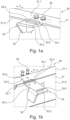
- the Figures 1a and 1b show a load-bearing device 30 with a profile 31 and a connecting piece 32.
- the profile 31 has a first wall 31.1 and a second wall 31.2 connected at right angles to the first wall 31.1.
- the profile 31 also has, but not shown, a third wall and a fourth wall and in this respect forms a hollow profile, for example as an upper chord 4.1 or lower chord 4.2 of a support structure 2 for a guideway device 1.
- a first recess 33.1 is arranged on the second wall 31.2, which is aligned in an alignment direction F.
- the alignment direction F is aligned parallel to the first wall 31.1.
- the connecting piece 32 has a first section 32.1 with which it passes through the first recess 33.1, so that the first section 32.1 rests against an inner side of the first wall 31.1.
- third recesses 33.3 are arranged, which are aligned with fourth recesses 33.4 in the first wall 31.1 and serve to connect the connecting piece 32 to the first wall 31.1 by means of connecting means 34.
- a thread (not shown in detail) is formed in the third recesses 33.3, into which the connecting means 34 are screwed.
- the connecting piece further comprises a second section 32.2 in which a second recess 33.2 designed as an elongated hole is arranged.
- the second Recess 33.2 serves as a load-bearing means for receiving a load, for example in the form of a component, in particular a comb plate, of a guideway device.
- a stop 35 designed as an angle is arranged on the second section 32.2, by means of which the first section 32.1 penetrating into the profile 31 is determined in terms of its length or position relative to the profile 31.
- the stop 35 creates an additional introduction of a force and/or a moment into the profile 31.
- a notch 35.1 is formed on an upper edge of the stop 35, by means of which striking against a weld seam provided between the first wall 31.1 and the second wall 31.2, but not shown, is avoided, so that the stop 35 rests securely against the second wall 31.2.
- a fifth recess 33.5 is also provided on the first wall 31.1, which adjoins the first recess 33.1, thus forming a single recess with it that extends over the first wall 31.1 and the second wall 31.2.
- the fifth recess 33.5 serves to expose the second recess, as shown in Figure 1a shown.
- a nut or a screw head can then rest against the second recess 33.2 without striking the first wall 31.1 or being hindered in its positioning or effect by the first wall 31.1.
- the Figures 2a to 2c show several longitudinal section modules 1.1, 1.2, 1.3 of a modularly assembled guideway device 1, namely Figure 2a a first longitudinal section module 1.1 designed as a lower head module, Figure 2b a second longitudinal section module 1.2 designed as an intermediate module and Figure 2c a third longitudinal section module 1.3 designed as an upper head module.
- the head modules extend beyond bends or have a bent stub.
- the longitudinal section modules 1.1, 1.2, 1.3 each have a support structure 2 with two side wall units 2.1, 2.2 extending mainly in a longitudinal direction L and cross beams 2.3 extending in a transverse direction Q.
- Each side wall unit 2.1, 2.2 in turn has a side wall 3, an upper flange 4.1 extending in the longitudinal direction L and a lower flange 4.2 extending in the longitudinal direction L.
- the structure of the supporting structures 2 is in the Figure 2d shown in detail.
- the side wall 3 is made of a flat material in which structural sections 6.1 and structural sections 6.2 are formed by recesses 5.
- the structural sections 6.1 divide the side wall 3 or the side wall unit 2 into fields.
- structural posts 7 with support elements 7.1 and the cross struts 2.3 are arranged or fastened, in particular welded, to the structural sections 6.1.
- the side wall 3 is also formed integrally with the upper flange 4.1 and the lower flange 4.2.
- a first wall 8.1 is formed by the flat material forming the side wall 3 and a second wall 8.2 of the upper flange 4.1 is bent in an L-shape from the first wall 8.1.
- a third wall 8.3 and a fourth wall 8.4 of the upper flange 4.1 are formed by a further element made from an L-shaped bent flat material and welded to the flat material forming the side wall 3.
- a first wall 9.1 is formed by the flat material forming the side wall 3 and an L-shape bent from the side wall 3 and a second wall 9.2 of the lower flange 4.2 is bent in an L-shape from the first wall 9.1.
- a third wall 9.3 and a fourth wall 9.4 of the lower chord 4.2 are formed by an L-shaped bent floor unit 10.
- a load-bearing device 30 as described above can, for example, but not shown in more detail, be formed on an upper chord 4.1 or a lower chord 4.2 and carry a component of the guideway device 1.
- the first wall 31.1 corresponds to the second wall 8.2 and the second wall 31.2 to the third wall 8.3.
- the longitudinal section modules 1.1, 1.2, 1.3 are shown with several components of the guideway device.
- the lower head module ( Fig. 2a ) a comb plate 12, a base 13, a balustrade 16 with a handrail 17 arranged thereon and several guides 14.1, 14.2, 14.3 for chain rollers, step/pallet rollers and/or a handrail (not shown).
- Corresponding guides 14.1, 14.2, 14.3, a base 13 and a balustrade 16 are also in the intermediate module ( Fig.2b ).
- the guides 14.1, 14.2, 14.3 rest on the support elements 7.1.
- the upper head module ( Fig. 2a ) a comb plate 12, a base 13, a balustrade 16 with a handrail 17 arranged thereon and several guides 14.1, 14.2, 14.3 for chain rollers, step/pallet rollers and/or a handrail (not shown).
- Corresponding guides 14.1, 14.2, 14.3, a base 13 and a balustrade 16 are also in the intermediate module ( Fig.2
- the components present in the lower head module and/or intermediate module have a drive 15 for driving a chain and/or a handrail circuit.
- a balustrade 16 provided is not shown.
- the comb plate 12 is held on the upper chord 4.1 in a manner not shown by a load-bearing device 30.
- the longitudinal modules 1.1, 1.2, 1.3 each have reference points 18 on the supporting structures 2, or side wall units 2.1, 2.2, or side walls 3 in the flat material, which in Figure 2d are shown.
- the reference points 18 are covered by mounting brackets 19, which in turn are fastened to slides 20.
- the reference points 18 are formed on the flat material by laser cutting during manufacture of the side walls 3, whereby, due to the accuracy typical of laser cutting, all other recesses or cutouts made in the flat material are positioned exactly opposite the reference points 18 and can therefore in turn serve as references when positioning/aligning components.
- the comb plate 12 can then be positioned and aligned using the load-bearing device 30 due to the exact references, without any additional aids or process steps being necessary.
- the suitability for positioning/alignment also applies to the connecting means 21 for connecting the longitudinal section modules 1.1, 1.2, 1.3 and slots 22 for receiving components of the guideway device 1 such as the support elements 7.1.
- the connecting means 21 for connecting the longitudinal section modules 1.1, 1.2, 1.3 and slots 22 for receiving components of the guideway device 1 such as the support elements 7.1.
Landscapes
- Escalators And Moving Walkways (AREA)
Priority Applications (5)
| Application Number | Priority Date | Filing Date | Title |
|---|---|---|---|
| EP22200510.0A EP4353653A1 (fr) | 2022-10-10 | 2022-10-10 | Dispositif de réception de charge destiné à recevoir une charge sur un profilé, en particulier dans un transporteur de passagers |
| EP22202864.9A EP4353664A1 (fr) | 2022-10-10 | 2022-10-20 | Dispositif de voie de circulation comportant au moins trois sections longitudinales, procédé et utilisation |
| PCT/EP2023/076283 WO2024078846A1 (fr) | 2022-10-10 | 2023-09-22 | Dispositif de réception de charge destiné à recevoir une charge sur un profil, en particulier dans un dispositif de transport de personnes |
| CN202380071954.9A CN120035560A (zh) | 2022-10-10 | 2023-09-27 | 具有至少三个纵向区段的行进装置、以及方法和应用 |
| PCT/EP2023/076727 WO2024078878A1 (fr) | 2022-10-10 | 2023-09-27 | Système de guidage comprenant au moins trois sections longitudinales, procédé et utilisation |
Applications Claiming Priority (1)
| Application Number | Priority Date | Filing Date | Title |
|---|---|---|---|
| EP22200510.0A EP4353653A1 (fr) | 2022-10-10 | 2022-10-10 | Dispositif de réception de charge destiné à recevoir une charge sur un profilé, en particulier dans un transporteur de passagers |
Publications (1)
| Publication Number | Publication Date |
|---|---|
| EP4353653A1 true EP4353653A1 (fr) | 2024-04-17 |
Family
ID=83689531
Family Applications (1)
| Application Number | Title | Priority Date | Filing Date |
|---|---|---|---|
| EP22200510.0A Pending EP4353653A1 (fr) | 2022-10-10 | 2022-10-10 | Dispositif de réception de charge destiné à recevoir une charge sur un profilé, en particulier dans un transporteur de passagers |
Country Status (2)
| Country | Link |
|---|---|
| EP (1) | EP4353653A1 (fr) |
| WO (1) | WO2024078846A1 (fr) |
Citations (2)
| Publication number | Priority date | Publication date | Assignee | Title |
|---|---|---|---|---|
| EP1655260A1 (fr) | 2004-11-08 | 2006-05-10 | Inventio Ag | Escalier mécanique ou trottoir roulant |
| EP4050171A1 (fr) * | 2021-02-24 | 2022-08-31 | Kamal Bouaouaja | Élément de liaison pour un châssis, ainsi que son procédé de fabrication |
-
2022
- 2022-10-10 EP EP22200510.0A patent/EP4353653A1/fr active Pending
-
2023
- 2023-09-22 WO PCT/EP2023/076283 patent/WO2024078846A1/fr not_active Ceased
Patent Citations (2)
| Publication number | Priority date | Publication date | Assignee | Title |
|---|---|---|---|---|
| EP1655260A1 (fr) | 2004-11-08 | 2006-05-10 | Inventio Ag | Escalier mécanique ou trottoir roulant |
| EP4050171A1 (fr) * | 2021-02-24 | 2022-08-31 | Kamal Bouaouaja | Élément de liaison pour un châssis, ainsi que son procédé de fabrication |
Also Published As
| Publication number | Publication date |
|---|---|
| WO2024078846A1 (fr) | 2024-04-18 |
Similar Documents
| Publication | Publication Date | Title |
|---|---|---|
| EP3472084B1 (fr) | Procede de modernisation d'un escalier ou d'un trottoir roulant | |
| EP2900585B1 (fr) | Système de voie pour un escalier roulant ou un trottoir roulant | |
| AT390598B (de) | Maschinentisch in modulbauweise fuer fertigungseinrichtungen | |
| EP3243694B1 (fr) | Procédé destiné au montage d'un système de sièges dans un véhicule et véhicule | |
| DE102013203457B4 (de) | Gestell einer Wäge-Fördervorrichtung | |
| DE2638440B2 (de) | Ueberschlagschutzrahmen fuer kraftfahrzeuge | |
| EP4353653A1 (fr) | Dispositif de réception de charge destiné à recevoir une charge sur un profilé, en particulier dans un transporteur de passagers | |
| EP2427609B1 (fr) | Système d'échafaudage, procédé de montage d'un système d'échafaudage et procédé d'utilisation d'un tel système | |
| WO2024078841A1 (fr) | Ensemble raccordement de module de section longitudinale et procédé d'assemblage d'appareil à chenille | |
| EP4353650B1 (fr) | Structure de support pour un dispositif de voie de circulation | |
| EP4353657A1 (fr) | Dispositif de réception de charge destiné à recevoir une charge sur un profilé, en particulier dans un dispositif de voie de circulation | |
| EP4353656A1 (fr) | Structure de support pour un dispositif de voie de circulation | |
| EP4353651A1 (fr) | Structure de support pour un dispositif de voie de circulation | |
| EP4353662A1 (fr) | Dispositif de voie de circulation comprenant une structure porteuse et des éléments de revêtement | |
| WO2006037549A1 (fr) | Cadre auxiliaire pour cadre de chassis de vehicule utilitaire | |
| EP4353658B1 (fr) | Procédé d'assemblage d'un dispositif de voie modulaire et dispositif et utilisation | |
| EP4353663A1 (fr) | Procédé de fabrication d'un composant d'un dispositif de voie de circulation | |
| EP4353661A1 (fr) | Socle pour dispositif de voie modulaire | |
| EP4353654A1 (fr) | Dispositif de voie de circulation comportant au moins trois sections longitudinales, procédé et utilisation | |
| EP4353660A1 (fr) | Dispositif de voie de circulation comprenant au moins trois modules de section longitudinale avec des sections longitudinales pouvant être accouplées par complémentarité de forme ainsi que procédé d'assemblage et utilisation | |
| EP4353664A1 (fr) | Dispositif de voie de circulation comportant au moins trois sections longitudinales, procédé et utilisation | |
| EP4353652A1 (fr) | Procédé d'assemblage modulaire d'au moins un module de section longitudinale d'un dispositif de voie de circulation à assemblage modulaire, dispositif de voie de circulation | |
| WO2024078878A1 (fr) | Système de guidage comprenant au moins trois sections longitudinales, procédé et utilisation | |
| WO2024078839A1 (fr) | Système de guidage modulaire doté d'une liaison de module d'ajustement de forme/ de force, procédé et utilisation | |
| WO2024256045A1 (fr) | Dispositif de transport de charge pour fixer une balustrade à un dispositif de guidage |
Legal Events
| Date | Code | Title | Description |
|---|---|---|---|
| PUAI | Public reference made under article 153(3) epc to a published international application that has entered the european phase |
Free format text: ORIGINAL CODE: 0009012 |
|
| STAA | Information on the status of an ep patent application or granted ep patent |
Free format text: STATUS: THE APPLICATION HAS BEEN PUBLISHED |
|
| AK | Designated contracting states |
Kind code of ref document: A1 Designated state(s): AL AT BE BG CH CY CZ DE DK EE ES FI FR GB GR HR HU IE IS IT LI LT LU LV MC ME MK MT NL NO PL PT RO RS SE SI SK SM TR |
|
| STAA | Information on the status of an ep patent application or granted ep patent |
Free format text: STATUS: REQUEST FOR EXAMINATION WAS MADE |
|
| 17P | Request for examination filed |
Effective date: 20240507 |
|
| RBV | Designated contracting states (corrected) |
Designated state(s): AL AT BE BG CH CY CZ DE DK EE ES FI FR GB GR HR HU IE IS IT LI LT LU LV MC ME MK MT NL NO PL PT RO RS SE SI SK SM TR |
|
| STAA | Information on the status of an ep patent application or granted ep patent |
Free format text: STATUS: EXAMINATION IS IN PROGRESS |
|
| 17Q | First examination report despatched |
Effective date: 20250922 |
|
| STAA | Information on the status of an ep patent application or granted ep patent |
Free format text: STATUS: THE APPLICATION IS DEEMED TO BE WITHDRAWN |