EP4477802A1 - Élément d'insonorisation - Google Patents
Élément d'insonorisation Download PDFInfo
- Publication number
- EP4477802A1 EP4477802A1 EP24177654.1A EP24177654A EP4477802A1 EP 4477802 A1 EP4477802 A1 EP 4477802A1 EP 24177654 A EP24177654 A EP 24177654A EP 4477802 A1 EP4477802 A1 EP 4477802A1
- Authority
- EP
- European Patent Office
- Prior art keywords
- soundproofing
- rail
- soundproofing element
- sound
- sound absorbers
- Prior art date
- Legal status (The legal status is an assumption and is not a legal conclusion. Google has not performed a legal analysis and makes no representation as to the accuracy of the status listed.)
- Pending
Links
Images




Classifications
-
- E—FIXED CONSTRUCTIONS
- E01—CONSTRUCTION OF ROADS, RAILWAYS, OR BRIDGES
- E01F—ADDITIONAL WORK, SUCH AS EQUIPPING ROADS OR THE CONSTRUCTION OF PLATFORMS, HELICOPTER LANDING STAGES, SIGNS, SNOW FENCES, OR THE LIKE
- E01F8/00—Arrangements for absorbing or reflecting air-transmitted noise from road or railway traffic
-
- E—FIXED CONSTRUCTIONS
- E01—CONSTRUCTION OF ROADS, RAILWAYS, OR BRIDGES
- E01F—ADDITIONAL WORK, SUCH AS EQUIPPING ROADS OR THE CONSTRUCTION OF PLATFORMS, HELICOPTER LANDING STAGES, SIGNS, SNOW FENCES, OR THE LIKE
- E01F8/00—Arrangements for absorbing or reflecting air-transmitted noise from road or railway traffic
- E01F8/0005—Arrangements for absorbing or reflecting air-transmitted noise from road or railway traffic used in a wall type arrangement
- E01F8/0029—Arrangements for absorbing or reflecting air-transmitted noise from road or railway traffic used in a wall type arrangement with porous surfaces, e.g. concrete with porous fillers
-
- E—FIXED CONSTRUCTIONS
- E01—CONSTRUCTION OF ROADS, RAILWAYS, OR BRIDGES
- E01F—ADDITIONAL WORK, SUCH AS EQUIPPING ROADS OR THE CONSTRUCTION OF PLATFORMS, HELICOPTER LANDING STAGES, SIGNS, SNOW FENCES, OR THE LIKE
- E01F8/00—Arrangements for absorbing or reflecting air-transmitted noise from road or railway traffic
- E01F8/0005—Arrangements for absorbing or reflecting air-transmitted noise from road or railway traffic used in a wall type arrangement
- E01F8/0023—Details, e.g. foundations
-
- E—FIXED CONSTRUCTIONS
- E04—BUILDING
- E04B—GENERAL BUILDING CONSTRUCTIONS; WALLS, e.g. PARTITIONS; ROOFS; FLOORS; CEILINGS; INSULATION OR OTHER PROTECTION OF BUILDINGS
- E04B1/00—Constructions in general; Structures which are not restricted either to walls, e.g. partitions, or floors or ceilings or roofs
- E04B1/62—Insulation or other protection; Elements or use of specified material therefor
- E04B1/74—Heat, sound or noise insulation, absorption, or reflection; Other building methods affording favourable thermal or acoustical conditions, e.g. accumulating of heat within walls
- E04B1/82—Heat, sound or noise insulation, absorption, or reflection; Other building methods affording favourable thermal or acoustical conditions, e.g. accumulating of heat within walls specifically with respect to sound only
- E04B1/84—Sound-absorbing elements
-
- E—FIXED CONSTRUCTIONS
- E04—BUILDING
- E04B—GENERAL BUILDING CONSTRUCTIONS; WALLS, e.g. PARTITIONS; ROOFS; FLOORS; CEILINGS; INSULATION OR OTHER PROTECTION OF BUILDINGS
- E04B1/00—Constructions in general; Structures which are not restricted either to walls, e.g. partitions, or floors or ceilings or roofs
- E04B1/62—Insulation or other protection; Elements or use of specified material therefor
- E04B1/74—Heat, sound or noise insulation, absorption, or reflection; Other building methods affording favourable thermal or acoustical conditions, e.g. accumulating of heat within walls
- E04B1/82—Heat, sound or noise insulation, absorption, or reflection; Other building methods affording favourable thermal or acoustical conditions, e.g. accumulating of heat within walls specifically with respect to sound only
- E04B2001/8263—Mounting of acoustical elements on supporting structure, e.g. framework or wall surface
Definitions
- the invention relates to a soundproofing element according to the preamble of patent claim 1.
- noise barriers or noise protection embankments on roads or railway lines to at least partially prevent the spread of sound.
- noise protection elements or soundproofing elements are used for this purpose, which are mounted, for example, on a vehicle restraint system on a road, on underground car park entrances or on building fences.
- Such soundproofing elements usually have absorber bodies, which are often made of wood concrete, comprising fresh wood chips mixed with cement and water.
- the object of the invention is therefore to provide a soundproofing element of the type mentioned at the outset, with which the disadvantages mentioned can be avoided and which can be quickly and easily installed at a predeterminable installation location and arranged on a base body.
- the combination of the at least one rail and the continuous grooves of the sound absorbers means that the soundproofing element can be installed at the installation location particularly quickly, since the sound absorbers only have to be laid out in a row on a floor and connected to the at least one rail. must be connected to each other.
- each sound absorber does not have to be attached to the base body individually, but rather a package of sound absorbers connected to the at least one rail can be attached to the base body.
- the at least one rail can hold the sound absorbers together on the rail and, on the other hand, the soundproofing element can be attached to the base body in a simple manner, for example to a wall or ceiling.
- the invention further relates to a modular soundproofing element according to claim 8.
- the invention further relates to an arrangement comprising a plurality of soundproofing elements according to claim 12.
- the invention further relates to a method for fastening a soundproofing element to a base body according to patent claim 15.
- the invention therefore has the further object of specifying a method of the type mentioned at the outset, with which the disadvantages mentioned can be avoided, with which soundproofing elements can be quickly and easily installed at a predeterminable installation location and arranged on a base body.
- Fig. 1 to 12 show at least parts of preferred embodiments of a soundproofing element 1 comprising a plurality of sound absorbers 2 arranged in a row and at least one rail 3, wherein each sound absorber 2 has at least one continuous groove 5 on a first side 4, wherein the at least one rail 3 is arranged in the grooves 5 of the sound absorbers 2, which at least one rail 3 connects the sound absorbers 2 arranged in a row to one another.
- a modular sound insulation system 9 comprising at least one Soundproofing element 1 and at least one fastening device 10 for fastening to a base body 7, in particular to a wall or to a ceiling, are provided, wherein at least one connecting device 6 of the at least one soundproofing element 1 is detachably coupled to the at least one fastening device 10.
- an arrangement comprising a plurality of soundproofing elements 1 is provided, wherein the soundproofing elements 1 are at least indirectly attached to a wall and form a predeterminable wall arrangement.
- the majority of the sound absorbers 2 and the at least one rail 3 can be prefabricated in a factory and the construction of the soundproofing element 1 at a predeterminable installation location can be carried out particularly easily and quickly.
- the combination of the at least one rail 3 and the continuous grooves 5 of the sound absorbers 2 means that the soundproofing element 1 can be constructed particularly quickly at the installation location, since only the sound absorbers 2 have to be laid out in a row on a floor and connected to one another with the at least one rail 3.
- each sound absorber 2 does not have to be attached to the base body 7 individually, but rather a package of sound absorbers 2 connected to the at least one rail 3 can be attached to the base body 7.
- the at least one rail 3 can thereby be used to hold the sound absorbers 2 together on the rail 3 and, on the other hand, to attach the soundproofing element 1 to the base body 7 in a simple manner, such as to a wall or a ceiling.
- the soundproofing element 1 is a device for insulating sound, in particular noise.
- the soundproofing element 1 can be used to reduce noise, i.e. sounds that are unpleasant for people and/or animals due to their structure, such as their volume.
- the soundproofing element 1 comprises a plurality of sound absorbers 2 arranged in a row.
- a sound absorber 2 is a component that is intended to reduce and/or diminish the spread of sound.
- the sound absorber 2 can preferably be made of wood concrete.
- the wood concrete preferably comprises wood chips and a binding agent, in particular cement or a synthetic resin.
- the sound absorber 2 can preferably also be referred to as a sound absorbing brick.
- the sound absorber 2 can be made of another sound-reducing material, whereby materials of this kind are known to a person skilled in the art and therefore a list of suitable materials is not provided here.
- the soundproofing element 1 can comprise at least two, particularly preferably at least four, in particular at least six, sound absorbers 2 arranged in a row.
- Fig. 10 a preferred embodiment of the soundproofing element 1 with six sound absorbers 2 arranged in a row is shown.
- the soundproofing element 1 can comprise a maximum of thirty, particularly preferably a maximum of twenty, in particular a maximum of ten, sound absorbers 2 arranged in a row.
- the sound absorbers 2 are preferably first lined up on a floor in such a way that the first side 4 of the sound absorbers 2 faces away from the floor.
- a continuous groove 5 of one sound absorber 2 preferably adjoins a second continuous groove 5 of the other sound absorber 2 in such a way that the grooves 5 of the sound absorbers 2 lined up in a row form in particular a continuous groove on the soundproofing element 1.
- the at least one rail 3 is then preferably inserted into the grooves 5 of the sound absorbers 2 lined up in a row or into the continuous groove on the soundproofing element 1.
- at least one connecting device 6 can be attached to the at least one rail 3, which is explained in more detail below.
- the constructed soundproofing element 1 can then preferably be attached at least indirectly to the base body 7.
- the sound absorbers 2 arranged next to one another form a row.
- the soundproofing element 1 consists only of a row of sound absorbers 2.
- At least one sound absorber 2 of the sound absorbers 2 arranged in a row can be at least 30 cm, particularly preferably at least 40 cm, in particular at least 50 cm, high. It can be provided that the height 15 of the soundproofing element 1 corresponds to the height of the sound absorber 2.
- the height 15 of the soundproofing element 1 is shown as an example, whereby each sound absorber 2 has the same height and the height 15 of the soundproofing element 1 corresponds to the height of the individual sound absorbers 2.
- At least one sound absorber 2 of the lined-up sound absorbers 2, in particular each sound absorber 2 of the lined-up sound absorbers 2, can be a maximum of 150 cm, particularly preferably a maximum of 110 cm, in particular a maximum of 70 cm, high.
- At least one sound absorber 2 of the lined-up sound absorbers 2, in particular each sound absorber 2 of the lined-up Sound absorber 2 must be at least 10 cm, particularly preferably at least 15 cm, in particular at least 20 cm, wide.
- At least one sound absorber 2 of the lined-up sound absorbers 2, in particular each sound absorber 2 of the lined-up sound absorbers 2, can be a maximum of 80 cm, particularly preferably a maximum of 60 cm, in particular at least 40 cm, wide.
- the groove 5 on the first side 4 of the respective sound absorber 2 extends over the entire width of the respective sound absorber 2.
- the surface area of the cross section of the at least one rail 3 corresponds to a maximum of 95 percent, particularly preferably a maximum of 85 percent, in particular a maximum of 75 percent, of the surface area of the respective cross section of the grooves 5 of the sound absorber 2. This also makes it possible to reduce or avoid constraints and stress peaks in the soundproofing element 1.
- the surface area of the cross section of the at least one rail 3 preferably corresponds to a maximum of 95 percent, particularly preferably a maximum of 85 percent, in particular a maximum of 75 percent, of the surface area of the cross section of that groove 5 of the sound absorber 2 in which the at least one rail 3 is arranged.
- the grooves 5 of the sound absorbers 2 have a substantially constant cross-section when viewed along the at least one rail 3.
- the grooves 5 of the sound absorbers 2 can be undercut.
- the respective cross section of the grooves 5 of the sound absorbers 2 is dovetail-shaped.
- the grooves 5 of the sound absorbers 2 preferably have a dovetail-shaped cross section.
- Each sound absorber 2 preferably has a dovetail-shaped cross section.
- the at least one continuous groove 5 of the respective sound absorber 2 is arranged on the first side 4.
- the first side 4 can also be referred to as the back of the respective sound absorber 2.
- Fig. 10 The back sides or the first sides 4 of the sound absorbers 2 arranged in a row are shown as examples.
- the first side 4 faces the base body 7 when the soundproofing element 1 is fastened to the base body 7.
- a second side 16 is arranged opposite and at a distance from the first side 4 of the respective sound absorber 2.
- the second side 16 of the respective sound absorber 2 can also be referred to as the front side of the respective sound absorber 2.
- the second side 16 of the sound absorbers 2 of the soundproofing element 1 arranged in a row points away from the base body 7 when the soundproofing element 1 is attached to the base body 7.
- the soundproofing element 1 comprises at least one rail 3.
- the at least one rail 3 can be made of metal, in particular of steel or aluminum.
- the at least one rail 3 can also be referred to as a profile bar.
- a cross-section of the at least one rail 3 can be substantially trapezoidal.
- At least one connecting device 6 is arranged on the at least one rail 3, which at least one connecting device 6 is designed for fastening the soundproofing element 1 to a base body 7, in particular to a wall or to a ceiling. This makes it particularly easy to fasten the sound absorbers 2 to the at least one rail 3, in particular if the grooves 5 of the sound absorbers 2 are undercut.
- the soundproofing element 1 comprises at least one connecting device 6.
- the at least one rail 3 can have at least one rail opening 17 for fastening the at least one connecting device 6 by means of a fastening means 18 to the at least one rail 3.
- the at least one rail 3 can have a plurality of rail openings 17.
- the at least one rail 3 can have at least one rail opening 17, in particular two rail openings 17, for each connecting device 6.
- the at least one connecting device 6 is fastened to the at least one rail 3, in particular by means of fastening means 18.
- the at least one connecting device 6 can have several Connecting device openings 19.
- the connecting device opening 19 is designed such that the connecting device 6 can be fastened to the at least one rail 3 by means of the fastening means 18.
- Fig. 10 1 shows an example of a soundproofing element 1 with four connecting devices 6. These four connecting devices 6 are each attached to the rail 3 so as to be adjacent to two sound absorbers 2 arranged adjacent to one another, with the respective connecting device 6 having two connecting device openings 19.
- Fig. 11 a preferred embodiment of the connecting device 6 can be seen in rear view, wherein two connecting device openings 19 are visible.
- Fig. 12 is the cut according to AA of the Fig. 11 shown preferred embodiment of the connecting device 6 is shown, wherein the connecting device opening 19 is also visible.
- the at least one connecting device 6 can be made of metal, in particular of steel or aluminum.
- the at least one connecting device 6 is formed in one piece.
- one piece means that the connecting device 6 consists of only one part or piece.
- the at least one rail 3 is pressed against at least one of the sound absorbers 2 arranged in a row by means of the at least one connecting device 6.
- This can be achieved, for example, by a screw connection between the at least one rail 3 and the at least one connecting device 6.
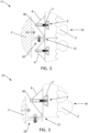
- a screw connection between the at least one rail 3 and the at least one connecting device 6. This is shown by way of example in the Fig. 1 to 3 visible, wherein by means of the fastening means 18 the at least one rail 3 is pulled in the direction of the at least one connecting device 6 and thereby the at least one rail 3 is pressed against the sound absorber 2 shown.
- the Fig. 1 to 3 visible, wherein by means of the fastening means 18 the at least one rail 3 is pulled in the direction of the at least one connecting device 6 and thereby the at least one rail 3 is pressed against the sound absorber 2 shown.
- FIG. 1 to 3 show a sectional view of a preferred embodiment of the modular soundproofing system 9, wherein the sectional view shows on the one hand a horizontal fastening of two soundproofing elements 1 arranged one above the other in side view and on the other hand a vertical fastening of two soundproofing elements 1 arranged next to each other in Top view.
- this makes it particularly easy to clamp the at least one rail 3 against the at least one sound absorber 2.
- the at least one connecting device 6 has a connecting surface 8, which connecting surface 8 rests against two sound absorbers 2 of the sound absorbers 2 of the soundproofing element 1 that are arranged next to one another.
- This allows two sound absorbers 2 to be quickly attached to the at least one rail 3, with only one connecting device 6 being required for the two sound absorbers 2.
- this allows a particularly firm connection of the sound absorbers 2 to the at least one rail 3, whereby displacement of the sound absorbers 2 can be effectively reduced when a motor vehicle collides with the soundproofing element 1.
- the connecting surface 8 rests on the respective first sides 4 of the two sound absorbers 2 of the sound absorbers 2 arranged in a row. This is exemplified in the Fig. 10 , where four connecting devices 6 are visible, each of which is connected to two sound absorbers 2.
- the connecting surface 8 is a substantially planar, in particular flat, surface of the at least one connecting device 6.
- the width 14 of the soundproofing element 1 can be at least 80 cm, particularly preferably at least 100 cm, in particular at least 120 cm.
- the width 14 of the soundproofing element 1 can be a maximum of 250 cm, particularly preferably a maximum of 200 cm, in particular a maximum of 150 cm.
- the height 15 of the soundproofing element 1 can be at least 20 cm, at least 30 cm, in particular at least 40 cm.
- the height 15 of the soundproofing element 1 can be a maximum of 100 cm, particularly preferably a maximum of 80 cm, in particular a maximum of 60 cm.
- the at least one connecting device 6 can be used to fasten the soundproofing element 1 to the base body 7. It is provided that the at least one connecting device 6 is designed to fasten the soundproofing element 1 to the base body 7. Preferably, the at least one connecting device 6 can be fastened to the base body 7 by means of base body fastening means, such as screws or bolts or nails. This is shown in the Fig. 1 to 12 but not apparent.
- the soundproofing element 1 can also be attached directly to the base body 7, in particular by means of the base body fastening means.
- the use of at least one connecting device 6 for fastening to the base body 7 is omitted.
- the soundproofing element 1 can be drilled through, for example after the soundproofing element 1 has been constructed, and attached directly to the base body 7, for example a wall or a ceiling, by means of the base body fastening means. This variant of fastening to the base body 7 is shown in the Fig. 1 to 12 not shown.
- the base body 7 can preferably be a wall or a ceiling, in particular comprising concrete.
- the soundproofing element 1 can be arranged at an underground car park entrance or on a concrete barrier wall by means of the connecting device 6 or another fastening.
- the modular soundproofing system 9 comprises at least one fastening device 10.
- the modular soundproofing system 9 can comprise several fastening devices 10.
- the at least one connecting device 6 is detachably coupled to the at least one fastening device 10 via a tongue and groove connection 13. This makes it particularly easy and quick to couple the at least one connecting device 6 with the fastening device 10, whereby the arrangement of the soundproofing elements 1 on the base body 7 can be carried out particularly easily, since only the fastening device 10 has to be fastened to the base body 7 and then the soundproofing element 1 has to be coupled to the fastening device 10 by means of the tongue and groove connection 13. This means that a damaged soundproofing element 1 can be replaced easily and quickly without the fastening device 10 having to be removed from the base body 7.
- a soundproofing element 1 can be clamped easily and quickly by means of two fastening devices 10, whereby the soundproofing element 1 can also be arranged flexibly, for example horizontally or vertically.
- the soundproofing element 1 can also be arranged flexibly, for example horizontally or vertically.
- a cross section of the fastening device 10 can be substantially L-shaped.
- the fastening device 10 can be designed like a hook, wherein the soundproofing element 1 can be hooked into the fastening device 10.
- the fastening device 10 can be designed in two parts.
- a first part 20 of the fastening device 10 can have a first contact surface and a second part 21 can have a second contact surface that is designed opposite to the first contact surface, wherein the first contact surface can be connected to the second contact surface in a form-fitting manner.
- the two contact surfaces, i.e. the first and the second contact surface, can in particular be designed in a sawtooth-like manner.
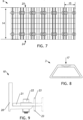
- the second part 21 of the fastening device 10 can be fastened to the first part 20 of the fastening device 10 by means of a fastening device means 22, in particular a screw. This is shown by way of example in Fig. 9 on a preferred embodiment of the fastening device 10.
- the fastening device 10 can have the bung 23 of the groove-bung connection 13.
- the second part 21 of the fastening device 10 can have a T-shaped cross section. This makes it particularly easy to form two bungs 23 for the tongue-and-groove connection 13.
- the second part 21 of the fastening device 10 can have a recess, in particular a slot, for the fastening device means 22.
- the variation of the distance between the bungs 23 and the first part 20 is shown by way of example in Fig. 9 visible.
- the fastening device 10 is made of metal, in particular steel or aluminum.
- the at least one connecting device 6 can have a connecting device groove 28 for the groove-bung connection 13.
- the connecting device groove 28 is shown by way of example in Fig. 12 shown.
- the at least one soundproofing element 1 has two oppositely arranged end regions, wherein in each end region at least one connecting device 6 is fastened to the at least one rail 3. This results in the advantage that the majority of sound absorbers 2 of the soundproofing element 1 can be easily fastened to the at least one rail 3, in particular if the sound absorbers 2 are undercut, by means of only the connecting devices 6 arranged at the end regions.
- the respective soundproofing element 1 can have a first transverse side 24 and a second transverse side 25 arranged opposite and at a distance from the first transverse side 24.
- the grooves 5 of the sound absorbers 2 arranged in a row form a continuous groove 5 on the soundproofing element 1, which extends from the first transverse side 24 to the second transverse side 25 of the soundproofing element 1.
- the first and second transverse sides 24, 24 of the soundproofing element 1 are shown by way of example in Fig. 10 visible.
- the respective end region of the soundproofing element 1 can extend at least 20 percent, particularly preferably at least 25 percent, in particular at least 30 percent, of the width 14 of the soundproofing element 1 along the at least one rail 3, in particular starting from the first transverse side 24 or the second transverse side 25, into the soundproofing element 1.
- each sound absorber 2 of the at least one soundproofing element 1 has at least two continuous grooves 5 on the first side 4, wherein a rail 3 is arranged in each of the two grooves 5 and that at least one connecting device 6 is fastened to each rail 3 in the end regions.
- a soundproofing element 1 preferably designed in this way is shown by way of example in Fig. 10 This allows the soundproofing element 1 to be designed to be particularly stable and to be arranged particularly flexibly on the base body 7.
- the soundproofing element 1 can be arranged horizontally on the base body 7, whereby in this arrangement several soundproofing elements 1 can be connected to one another on the transverse sides 24, 25, in particular arranged adjacent to one another. This is shown by way of example in the Fig.
- the soundproofing element 1 can be arranged vertically on the base body 7, whereby in this arrangement several soundproofing elements 1 can be connected to one another on the respective upper sides 26 or lower sides 27 of the soundproofing elements 1, in particular arranged adjacent to one another. This is shown by way of example in Fig. 7 visible, and the top 26 and the bottom 27 of the soundproofing element 1 in Fig. 10 shown as an example.
- the soundproofing element 1 has the underside 27 and the top side 26, wherein the underside 27 of the soundproofing element 1 is arranged opposite and spaced from the top side 26 of the soundproofing element 1.
- the at least two continuous grooves 5 are arranged substantially parallel to each other on the first sides 4 of the sound absorbers 2.
- the Bottom side 27 or top side 26 facing the ground.
- the first transverse side 24 or the second transverse side 25 of the soundproofing element 1 faces the floor.
- the arrangement can preferably comprise the modular soundproofing system 9, wherein fastening devices 10 for the soundproofing elements 1 are fastened to the wall, and wherein the at least one connecting device 6 of the respective soundproofing elements 1 is detachably coupled to the fastening devices 10.
- the predeterminable wall arrangement can be easily formed, since only the fastening devices 10 have to be fastened to the wall and the connecting devices 6 of the soundproofing elements 1 have to be coupled to the fastening devices 10.
- Fig. 2 visible, whereby Fig. 2 a first detail 11 from Fig. 1 Compared to Fig. 2 is in Fig. 3 a second detail 12 from Fig.
Landscapes
- Engineering & Computer Science (AREA)
- Architecture (AREA)
- Physics & Mathematics (AREA)
- Civil Engineering (AREA)
- Structural Engineering (AREA)
- Acoustics & Sound (AREA)
- Electromagnetism (AREA)
- Life Sciences & Earth Sciences (AREA)
- Sustainable Development (AREA)
- Building Environments (AREA)
- Soundproofing, Sound Blocking, And Sound Damping (AREA)
Applications Claiming Priority (1)
| Application Number | Priority Date | Filing Date | Title |
|---|---|---|---|
| ATA50470/2023A AT526859B1 (de) | 2023-06-15 | 2023-06-15 | Schallschutzelement |
Publications (1)
| Publication Number | Publication Date |
|---|---|
| EP4477802A1 true EP4477802A1 (fr) | 2024-12-18 |
Family
ID=91248168
Family Applications (1)
| Application Number | Title | Priority Date | Filing Date |
|---|---|---|---|
| EP24177654.1A Pending EP4477802A1 (fr) | 2023-06-15 | 2024-05-23 | Élément d'insonorisation |
Country Status (2)
| Country | Link |
|---|---|
| EP (1) | EP4477802A1 (fr) |
| AT (1) | AT526859B1 (fr) |
Citations (4)
| Publication number | Priority date | Publication date | Assignee | Title |
|---|---|---|---|---|
| DE7811940U1 (de) * | 1978-08-24 | Continental Gummi-Werke Ag, 3000 Hannover | Lärmschutzwand | |
| FR2715951A1 (fr) * | 1994-02-09 | 1995-08-11 | Bellion Patrick | Dispositif de fixation de dalles lourdes. |
| JPH09143936A (ja) * | 1995-11-17 | 1997-06-03 | Misawa Ceramics Kk | 防音ユニットパネルの取付構造 |
| WO2017139090A1 (fr) * | 2016-02-09 | 2017-08-17 | Knoll, Inc. | Dalle à base de liège destinée à des appareils de confidentialité et son procédé de fabrication et d'utilisation |
Family Cites Families (3)
| Publication number | Priority date | Publication date | Assignee | Title |
|---|---|---|---|---|
| US3924056A (en) * | 1973-12-13 | 1975-12-02 | James T Locicero | Slotted masonry wall structure and metal stud therefor |
| FR2486126A1 (fr) * | 1980-07-07 | 1982-01-08 | Ecomat Etude Const Materiel | Elements modulaires pour la construction de mur isolant thermique et phonique |
| DE3728103A1 (de) * | 1987-08-22 | 1989-03-02 | Nuedling Franz C Basaltwerk | Bauelement sowie verfahren zur herstellung desselben |
-
2023
- 2023-06-15 AT ATA50470/2023A patent/AT526859B1/de active
-
2024
- 2024-05-23 EP EP24177654.1A patent/EP4477802A1/fr active Pending
Patent Citations (4)
| Publication number | Priority date | Publication date | Assignee | Title |
|---|---|---|---|---|
| DE7811940U1 (de) * | 1978-08-24 | Continental Gummi-Werke Ag, 3000 Hannover | Lärmschutzwand | |
| FR2715951A1 (fr) * | 1994-02-09 | 1995-08-11 | Bellion Patrick | Dispositif de fixation de dalles lourdes. |
| JPH09143936A (ja) * | 1995-11-17 | 1997-06-03 | Misawa Ceramics Kk | 防音ユニットパネルの取付構造 |
| WO2017139090A1 (fr) * | 2016-02-09 | 2017-08-17 | Knoll, Inc. | Dalle à base de liège destinée à des appareils de confidentialité et son procédé de fabrication et d'utilisation |
Also Published As
| Publication number | Publication date |
|---|---|
| AT526859B1 (de) | 2024-08-15 |
| AT526859A4 (de) | 2024-08-15 |
Similar Documents
| Publication | Publication Date | Title |
|---|---|---|
| EP0744508B1 (fr) | Dispositif pour former une armature de cisaillement pour dalles plates | |
| CH687225A5 (de) | Kabelkanalanordnung. | |
| DE69306200T2 (de) | Zwischenträger zum Befestigen der Führungsschienen in einem Aufzugsschacht | |
| AT526859B1 (de) | Schallschutzelement | |
| EP0677622A2 (fr) | Caniveau pour la pose dans le sol | |
| EP1659222B1 (fr) | Élément antibruit, mur antibruit et procédé pour la production de l'élément antibruit | |
| DE102019124308A1 (de) | Verankerungselement und Verfahren zur Montage einer Ankerschiene in einem Baukörper aus Beton | |
| DE3241424C2 (de) | Verbindungseinrichtung | |
| EP1500827A1 (fr) | Système de construction modulaire | |
| EP3546666A1 (fr) | Module de raccordement bois-béton | |
| EP0412445A2 (fr) | Rail pouvant être encastré dans des poutres en béton ou similaires | |
| DE69613744T2 (de) | Schutzvorrichtung zum Verhindern des Eindringens von Wasser in eine Wand und zum Verbessern des Abführens von Wasser aus einer Wand | |
| DE69814708T2 (de) | Befestigungsvorrichtung zur Montage von Schallabsorptionselement am oberen Bereich einer Lärmschutzwand und Verfahren für dessen Befestigung | |
| DE102009049178A1 (de) | Schalung | |
| DE10139891C1 (de) | Leitschwellenstrang | |
| DE102016208028B4 (de) | Trägerbohlwand und Randwegkonstruktion | |
| EP3070225B1 (fr) | Élément d'armature de poinçonnement et construction dotée d'une plaque comprenant un élément d'armature de poinçonnement | |
| DE3632703A1 (de) | Fugen-schalungs-element | |
| EP1435416A1 (fr) | Caniveau d'écoulement et méthode de production d'un tel caniveau d'écoulement | |
| DE69011526T2 (de) | Anordnung in einem tunnelgewölbe. | |
| DE9404270U1 (de) | Pfosten | |
| DE3447645C2 (fr) | ||
| DE102005044787B4 (de) | Betonschwelle für Weichen | |
| CH703431A2 (de) | Baukonstruktionselement und entsprechendes Herstellungsverfahren für dieses. | |
| DE9406004U1 (de) | Montagehilfe zum Verlegen von Rinnen |
Legal Events
| Date | Code | Title | Description |
|---|---|---|---|
| PUAI | Public reference made under article 153(3) epc to a published international application that has entered the european phase |
Free format text: ORIGINAL CODE: 0009012 |
|
| STAA | Information on the status of an ep patent application or granted ep patent |
Free format text: STATUS: THE APPLICATION HAS BEEN PUBLISHED |
|
| AK | Designated contracting states |
Kind code of ref document: A1 Designated state(s): AL AT BE BG CH CY CZ DE DK EE ES FI FR GB GR HR HU IE IS IT LI LT LU LV MC ME MK MT NL NO PL PT RO RS SE SI SK SM TR |
|
| STAA | Information on the status of an ep patent application or granted ep patent |
Free format text: STATUS: REQUEST FOR EXAMINATION WAS MADE |
|
| 17P | Request for examination filed |
Effective date: 20250618 |