EP4477954A1 - Ofen mit offener flamme - Google Patents
Ofen mit offener flamme Download PDFInfo
- Publication number
- EP4477954A1 EP4477954A1 EP24181938.2A EP24181938A EP4477954A1 EP 4477954 A1 EP4477954 A1 EP 4477954A1 EP 24181938 A EP24181938 A EP 24181938A EP 4477954 A1 EP4477954 A1 EP 4477954A1
- Authority
- EP
- European Patent Office
- Prior art keywords
- oven
- floor
- flame
- open
- alcove
- Prior art date
- Legal status (The legal status is an assumption and is not a legal conclusion. Google has not performed a legal analysis and makes no representation as to the accuracy of the status listed.)
- Pending
Links
Images




Classifications
-
- A—HUMAN NECESSITIES
- A47—FURNITURE; DOMESTIC ARTICLES OR APPLIANCES; COFFEE MILLS; SPICE MILLS; SUCTION CLEANERS IN GENERAL
- A47J—KITCHEN EQUIPMENT; COFFEE MILLS; SPICE MILLS; APPARATUS FOR MAKING BEVERAGES
- A47J37/00—Baking; Roasting; Grilling; Frying
- A47J37/06—Roasters; Grills; Sandwich grills
- A47J37/0623—Small-size cooking ovens, i.e. defining an at least partially closed cooking cavity
- A47J37/0658—Small-size cooking ovens, i.e. defining an at least partially closed cooking cavity specially adapted for cooking pizza
-
- A—HUMAN NECESSITIES
- A47—FURNITURE; DOMESTIC ARTICLES OR APPLIANCES; COFFEE MILLS; SPICE MILLS; SUCTION CLEANERS IN GENERAL
- A47J—KITCHEN EQUIPMENT; COFFEE MILLS; SPICE MILLS; APPARATUS FOR MAKING BEVERAGES
- A47J37/00—Baking; Roasting; Grilling; Frying
- A47J37/06—Roasters; Grills; Sandwich grills
- A47J37/0623—Small-size cooking ovens, i.e. defining an at least partially closed cooking cavity
- A47J37/0647—Small-size cooking ovens, i.e. defining an at least partially closed cooking cavity with gas burners
-
- F—MECHANICAL ENGINEERING; LIGHTING; HEATING; WEAPONS; BLASTING
- F24—HEATING; RANGES; VENTILATING
- F24C—DOMESTIC STOVES OR RANGES ; DETAILS OF DOMESTIC STOVES OR RANGES, OF GENERAL APPLICATION
- F24C3/00—Stoves or ranges for gaseous fuels
- F24C3/02—Stoves or ranges for gaseous fuels with heat produced solely by flame
-
- F—MECHANICAL ENGINEERING; LIGHTING; HEATING; WEAPONS; BLASTING
- F24—HEATING; RANGES; VENTILATING
- F24C—DOMESTIC STOVES OR RANGES ; DETAILS OF DOMESTIC STOVES OR RANGES, OF GENERAL APPLICATION
- F24C3/00—Stoves or ranges for gaseous fuels
- F24C3/08—Arrangement or mounting of burners
- F24C3/085—Arrangement or mounting of burners on ranges
- F24C3/087—Arrangement or mounting of burners on ranges in baking ovens
Definitions
- the present disclosure relates to open-flame ovens and is particularly, although not exclusively, concerned with a domestic open-flame gas oven for pizza.
- Open-flame gas ovens for cooking foodstuffs are known.
- pizza ovens and particularly portable and domestic pizza ovens, it is desirable to provide improved portability and/or reduced oven size while maintaining high-temperature cooking performance. Portability and reduced size can limit the available cooking space in the oven, thereby limiting the utility of the oven for cooking larger foodstuffs.
- an open-flame oven may comprise an oven housing surrounding an oven chamber for containing foodstuffs during cooking.
- the oven housing may comprise an inner surface forming an internal wall of the oven chamber.
- the open-flame oven may further comprise an oven mouth for accessing the oven chamber and a substantially continuous oven floor forming a base of the oven chamber for supporting foodstuffs, the oven floor extending across the oven chamber from the oven mouth.
- the internal wall of the oven housing may comprise lateral wall sections extending generally upwardly along lateral sides of the oven floor.
- At least a portion of one of the lateral wall sections may be recessed laterally from the respective lateral side of the oven floor, thereby forming an alcove in the internal wall of the oven housing adjacent the lateral side of the oven floor.
- the open-flame oven may further comprise a gas burner arranged in the alcove adjacent the lateral side of the oven floor.
- the open-flame oven may further comprise a flame guard extending upwardly between the gas burner and the lateral side of the oven floor.
- a height of the flame guard above the oven floor may be adjustable. Additionally or alternatively, a plurality of interchangeable flame guards of different heights and/or thicknesses may be provided.
- the flame guard may comprise one or more apertures formed therethrough.
- the one or more apertures may provide improved airflow to the gas burner.
- the flame guard may be arcuate in plan view, or comprise distal portions angled away from the lateral side of the oven floor.
- the lateral sides of the oven floor may be substantially linear.
- a wall thickness of the oven housing may be commensurately thinner proximate the alcove.
- the outer surface of the oven housing may be undisturbed by the alcove. Such that the outer surface of the oven housing is smooth. This may provide a smooth surface to the exterior of the oven without any protuberances, thereby providing an oven with a smaller form.
- the alcove and gas burner may be situated adjacent a left lateral side of the oven floor, with respect to the oven mouth. This may provide good access to the oven, improved visibility of cooking, and a reduced risk of injury such as burns, as the majority of oven users are right handed.
- a width of the oven mouth may be substantially the same as a maximum width of the oven floor.
- the width of the oven floor and the lateral span between the lateral sides of the internal wall at the oven mouth may be the same as the oven mouth width.
- a rear edge of the oven floor opposite the oven mouth may be arcuate.
- the rear edge may form a part-circular arc or a semi-circular arc.
- the alcove may be formed over only a portion of the lateral side of the oven floor.
- the alcove may be formed over less than half of the length of the oven floor (i.e., the length from the oven mouth to the rear edge of the oven floor).
- the alcove may be elongate along the lateral side of the oven floor.
- the alcove may extend along the lateral side of the oven floor by a greater distance than its depth (i.e., its lateral depth from the oven floor).
- the gas burner may be elongate, in particular the head of the gas burner may be elongate.
- the head of the gas burner may have one dimension substantially larger than the perpendicular dimension.
- a venturi of the gas burner may be arranged substantially perpendicular to the major axis of the gas burner head, in particular in plan view.
- the head of the gas burner head may be fan-shaped. Gas burner head may be angled inwardly towards the oven chamber.
- the gas burner or the gas burner head, may be arranged above the level of the oven floor.
- a depth of the alcove i.e., the lateral recess of the lateral wall section from the oven floor
- a length of the alcove i.e., the length of the alcove along the lateral side of the oven floor
- the cross sectional size of the alcove may decrease with increasing elevation off the oven floor (i.e., the alcove becomes smaller at a greater height up the oven).
- the oven floor may be formed from ceramic or stone.
- the oven floor may not be perforated or slatted.
- the oven floor may be substantially impermeable.
- the oven floor may be formed of one contiguous plate, or may be formed from multiple plates which abut each other to form a substantially continuous surface.
- the internal wall of the oven is generally dome-shaped.
- the internal wall may be dome-shaped when viewed in front cross-section across the oven width.
- a forepart of the oven housing may extend forwardly above the oven mouth to thereby form an antechamber to the oven chamber.
- An oven flue may be formed in the forepart of the oven housing above the antechamber.
- No flue or aperture may be formed in the internal wall of the oven housing other than the oven mouth.
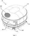
- FIG 1 shows a perspective view of an open-flame oven 10 in accordance with the present disclosure.
- Figures 2 and 3 show a front view and side view of the open-flame oven 10 respectively.
- the open-flame oven 10 will be referred to in the following detailed description as simply the "oven 10".
- the oven 10 comprises an oven housing 102 which surrounds an oven chamber 104 for containing foodstuffs during cooking (not shown).
- the base of the oven chamber 104 is formed by an oven floor 106, which is substantially continuous and provides a support surface for foodstuffs.
- the oven 10 further comprises an oven mouth 108, which is in the form of a large opening at the front of the oven housing 102 and which provides access to the oven chamber 104 to enable the placing of foodstuffs inside the oven chamber 104 for cooking.
- the oven chamber 104 is heated in order to cook foodstuffs placed within by a gas burner, which will be described further below.
- the oven floor 106 extends generally rearwardly within the oven housing 102 from the oven mouth, thereby forming the base of the oven chamber 104.
- the oven 10 is particularly suited to high-temperature cooking applications, such as pizza cooking, and may be capable of reaching temperatures up to around 500 degrees Celsius.
- the oven floor 106 which forms the base of the oven chamber 104.
- the oven floor 106 is configured to be arranged in a substantially horizontal plane in use, so as to provide a support surface for supporting foodstuffs to be cooked or cured in the oven chamber 104.
- the oven floor 106 is a stone floor in this example. Ovens of this type typically have this a thick heat-retaining floor which absorbs heat from the energy source of the oven such that the underside of foodstuffs (such as pizza) can be heated efficiently.
- the oven floor may be formed from other materials.
- the floor may be formed from, for example, stone, ceramic, or plate metal.
- the oven floor 106 is formed from a single floor panel. In other examples, a plurality of separate panels may be provided which abut to form a substantially continuous surface. The continuous surface may be formed from more than one floor panel, but there may be essentially no gaps between separate panels of the oven floor.
- the oven floor 106 is substantially impermeable.
- the oven 10 additionally comprises a burner adjuster 112, which allows the intensity of the flame (and thus the temperature of the oven chamber 104) to be adjusted, for example by adjusting the gas flow to the gas burner of the oven.
- a gas inlet port 114 is provided to connect the oven 10 to a source of gas, such as a gas cylinder or gas mains supply (not shown).
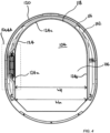
- FIG. 4 and 4A a sectional plan view of the oven 10 is shown, viewed on the plane A-A indicated in Figures 2 and 3 .
- the oven housing 102 is generally in the form of a dome-shaped housing which surrounds the oven chamber 104.
- the oven housing 102 comprises an inner surface 116 which forms an internal wall 118 of the oven chamber 104.
- the internal wall 118 defines the oven chamber 104.
- the internal wall 118 extends around three peripheral sides (left, right, and rear) of the oven floor 106, with the front of the oven housing comprising the oven mouth 108, providing access to the oven chamber 104.
- the internal wall 118 also extends over the oven chamber 104 in a dome-like manner, to substantially enclose the oven chamber 104.
- the internal wall 118 may be dome-shaped when viewed in front cross-section across the oven width, for example as shown in Figure 5 . Where left, right, front, and rear are discussed in this disclosure, it should be understood that these directions are with respect to the oven mouth 108.
- the internal wall 118 of the oven 10 is, in this example, formed of a continuous piece of material, such as sheet metal, which may provide simpler manufacture, fewer failure points, and prevent heat escaping the oven chamber, thereby improving heat retention and efficiency.
- the oven housing 102 further comprises an external wall 120, which is exposed to the external environment. Between the internal wall 118 and the external wall 120, a void 122 is formed.
- the void 122 may be filled with insulating material to reduce heat losses from the oven chamber 104 to the external environment.
- the width W m of the oven mouth 108 is configured to be substantially the same as the maximum width W f of the oven floor 106. This may provide improved access to the entire surface area of the oven floor 106.
- the oven floor 106 meets the internal wall 118 of the oven housing 102.
- the periphery of the oven floor 106 comprises three sections, a left lateral side 124a, a right lateral side 124b, and a rear side 124c.
- the left and right lateral sides 124a and 124b of the oven floor 106 are substantially linear and extend rearwardly from the oven mouth 108 in a substantially perpendicular direction to the span of the oven mouth 108.
- the rear side 124c of the oven floor 106 extends arcuately, in this example in a semicircle, between the left and right lateral sides 124a and 124b. This gives the rear of the oven floor 106 a semi-circular shape, which may be particularly beneficial when cooking foods which are circular in shape, such as pizza, as the food can more closely conform to the oven floor shape, thereby avoiding large areas of unused oven floor space, which may be present in, for example, the corners of a rectangular oven floor. This may in turn reduce the available surface area for heat losses and provide a particularly compact, efficient, and light oven.
- the internal wall 118 comprises left and right lateral wall sections (118a and 118b respectively) which correspond to, and extend generally upwardly adjacent, the lateral sides 124a and 124b of the oven floor 106.
- the lateral wall sections 118a and 118b curve inwardly with increasing elevation from the oven floor 106 and meet at the top of the oven chamber 104 to thereby form a dome-shaped roof of the oven chamber 104.
- a portion 126 of the left lateral wall section 118a is recessed laterally from the left lateral side 124a of the oven floor, thereby forming an alcove 128 in the internal wall 118 adjacent the lateral side 124a of the oven floor 106.
- the alcove 128 is formed on the left side of the oven floor 106, but it will be appreciated that an alcove could alternatively or additionally be formed at the right side of the oven floor, in the right lateral wall section 118b in substantially the same manner.
- the alcove 128 is, in this example, formed over only a portion of the left lateral side 118a of the oven floor 106. In particular, the alcove 128 is formed over less than half of the length of the oven floor (i.e., the distance from the oven mouth to the rear of the oven floor 106). The alcove 128 is also elongate along the left lateral side 124a of the oven floor 106; in other words, the alcove 128 extends a greater distance along the side of the oven floor 106 than the depth to which it is recessed laterally into the internal wall 118.
- a lateral depth of the alcove 128 decreases with increasing elevation off the oven floor 106.
- the alcove 128 gradually tapers at its upper end into the dome shape of the rest of the internal wall 118.
- a length of the alcove 128 i.e., the length of the alcove along the lateral side of the oven floor 106 decreases with increasing elevation off the oven floor 106.
- the cross sectional size of the alcove 128 decreases with increasing elevation off the oven floor 106 (i.e., the alcove becomes smaller at a greater height up the oven).
- the central section 128a of the alcove is substantially parallel to the left lateral side 124a of the oven floor, while the front and rear sections 128b of the alcove 128 are tapered between the central section and the rest of the internal wall 118 so as to provide a smooth transition between the alcove 128 and the internal wall 118.
- a gas burner 130 is provided in the alcove 128.
- the gas burner 130 is configured to receive gas fuel from a gas fuel source, and combust the gas in order to produce an open flame to heat the oven chamber 104 and the oven floor 106.
- An igniter 135 is provided to ignite the gas burner 130.
- a flame failure device 133 is also provided.
- only a single gas burner 130 is provided, on only one lateral side of the oven floor 106.
- the alcove 128 and gas burner 130 may be provided on the right side only, on both left and right sides, and even additionally at the rear side of the oven floor.
- Providing the gas burner 130 in the alcove 128 provides that the gas burner 130 does not encroach into the oven floor 106, and allows the oven floor 106 to have a smooth lateral edge shape. This may provide an increased cooking area, and may reduce stress concentrations in the oven floor 106, thereby reducing risk of damage or cracks to the oven floor 106. Additionally, providing the gas burner 130 in a laterally recessed alcove 128 may provide improved access to the oven chamber 104, improved visibility of cooking, as the hottest area of the oven chamber 104 is more easily visible. This may further provide user-friendliness, such as easier use, a reduced risk of injury such as burns. Providing the alcove and gas burner on the left side of the oven may be particularly beneficial, as the majority of the population, and thus oven users, are right handed.
- the gas burner 130 and particularly the outlet or head 131 of the gas burner 130, is elongate.
- the gas burner outlet 131 has a first dimension substantially larger than the perpendicular dimension.
- the major dimension of the gas burner 130 is aligned with the major axis of the alcove 128, and aligned with the lateral side 124a of the oven floor 106.
- the gas burner 130 is generally fan-shaped, as shown in Figure 6 in dotted lines, and the outlet 131 is angled inwardly towards the oven chamber 104, as shown in Figure 5 . This may provide particularly good heat distribution.
- a venturi mixer 132 is provided to mix air with the gas provided to the gas burner 130 for combustion.
- the venturi mixer 132 is elongate, and is arranged substantially perpendicular to the major axis of the gas burner 130 (in plan view). This may provide improved combustion and performance.
- the oven 10 additionally comprises a flame guard 134.
- the flame guard 134 extends upwardly between the gas burner 130 in the alcove 128 and the lateral side 124a of the oven floor 106.
- the flame guard is formed from, e.g., steel, and is arranged to guard the local region of the oven floor 106 and oven chamber 104 from the most intense radiated heat from the gas burner 130.
- the gas burner 130 and in particular the gas burner outlet 131 is arranged above the level of the oven floor 106. This may maximise the space below the oven floor 106 for other components and/or reduce the total height and size of the oven 10.
- the height of the flame guard 134 above the oven floor 106 may be adjustable. Additionally or alternatively, the oven 10 may be provided with a plurality of interchangeable flame guards of different heights and/or thicknesses to suit different use cases.
- the flame guard 134 has at least one aperture 136 formed therethrough, which may provide improved airflow to the gas burner. With reference to Figure 4A , the flame guard 134 has distal portions 134a which are angled away from the lateral side 124a of the oven floor 106, such that the flame guard 134 forms a generally curved shape.
- a forepart 138 of the oven housing 102 extends forwardly from above the oven mouth 108 to thereby form an antechamber 140 to the oven chamber 104.
- the oven flue 110 is formed through in the forepart 138 above the antechamber 140. This configuration provides that gas is expelled from the oven chamber 104 via the oven mouth 108, and can then exit upwardly through the flue 110. This may provide a cooler working environment for the user proximate the oven mouth 108. In this example, no flue or other aperture is formed in the internal wall 118 other than the oven mouth 108 itself.
- the features of the oven described above may provide various technical advantages.
- the oven may be particularly compact while providing improved oven floor space, for example because the gas burner does not encroach on the oven floor.
- the oven may provide improved visibility of the cooking process, greater manoeuvrability of cooking foodstuffs, and/or greater user control over the cooking process.
- the oven may provide more even heating throughout the oven chamber and/or reduce hot and cool spots within the oven chamber.
- the oven may provide tailored cooking conditions for certain foodstuffs, such as different pizza styles, thereby reducing the need to reposition foodstuffs during cooking.
- the oven may be particularly suited to cooking foodstuffs with large surface areas and/or circular shapes, such as pizza.
- the oven may provide improved gas burner performance and/or efficiency, for example by providing improved secondary airflow to the gas burner.
- the oven may minimise radiated heat transmitted directly from the burner to the foodstuffs, thereby reducing a risk of local burning of foodstuffs located close to the burner.
Landscapes
- Engineering & Computer Science (AREA)
- Food Science & Technology (AREA)
- Chemical & Material Sciences (AREA)
- Combustion & Propulsion (AREA)
- Mechanical Engineering (AREA)
- General Engineering & Computer Science (AREA)
- Baking, Grill, Roasting (AREA)
Applications Claiming Priority (1)
| Application Number | Priority Date | Filing Date | Title |
|---|---|---|---|
| GB2308784.4A GB2626206B (en) | 2023-06-13 | 2023-06-13 | Open-flame oven |
Publications (1)
| Publication Number | Publication Date |
|---|---|
| EP4477954A1 true EP4477954A1 (de) | 2024-12-18 |
Family
ID=87291507
Family Applications (1)
| Application Number | Title | Priority Date | Filing Date |
|---|---|---|---|
| EP24181938.2A Pending EP4477954A1 (de) | 2023-06-13 | 2024-06-13 | Ofen mit offener flamme |
Country Status (5)
| Country | Link |
|---|---|
| US (1) | US20240415327A1 (de) |
| EP (1) | EP4477954A1 (de) |
| AU (1) | AU2024203987A1 (de) |
| CA (1) | CA3241511A1 (de) |
| GB (1) | GB2626206B (de) |
Citations (8)
| Publication number | Priority date | Publication date | Assignee | Title |
|---|---|---|---|---|
| FR975769A (fr) * | 1948-12-02 | 1951-03-09 | Four de réchauffage et à recuire, à flamme horizontale déviée | |
| FR2486643A1 (fr) * | 1980-07-08 | 1982-01-15 | Riedhammer Ludwig Gmbh | Four pour la cuisson de pieces ceramiques |
| JP2000253801A (ja) * | 1999-03-08 | 2000-09-19 | Fujimura Seisakusho:Kk | ピザ用窯 |
| WO2005082213A1 (de) * | 2004-02-12 | 2005-09-09 | Jona Rosenkranz | Ofen zum backen, grillen oder garen von nahrungsmitteln |
| JP2006296237A (ja) * | 2005-04-18 | 2006-11-02 | Shichiyo Seisakusho:Kk | 電熱式ピザ用オーブン |
| JP2016174567A (ja) * | 2015-03-19 | 2016-10-06 | 有限会社藤村製作所 | ピザ用窯 |
| WO2021165261A1 (en) * | 2020-02-19 | 2021-08-26 | Gozney Group Limited | Oven |
| US11344032B1 (en) * | 2021-05-22 | 2022-05-31 | Halo Products Group, Llc | Portable baking oven |
-
2023
- 2023-06-13 GB GB2308784.4A patent/GB2626206B/en active Active
-
2024
- 2024-06-12 US US18/741,673 patent/US20240415327A1/en active Pending
- 2024-06-12 AU AU2024203987A patent/AU2024203987A1/en active Pending
- 2024-06-12 CA CA3241511A patent/CA3241511A1/en active Pending
- 2024-06-13 EP EP24181938.2A patent/EP4477954A1/de active Pending
Patent Citations (8)
| Publication number | Priority date | Publication date | Assignee | Title |
|---|---|---|---|---|
| FR975769A (fr) * | 1948-12-02 | 1951-03-09 | Four de réchauffage et à recuire, à flamme horizontale déviée | |
| FR2486643A1 (fr) * | 1980-07-08 | 1982-01-15 | Riedhammer Ludwig Gmbh | Four pour la cuisson de pieces ceramiques |
| JP2000253801A (ja) * | 1999-03-08 | 2000-09-19 | Fujimura Seisakusho:Kk | ピザ用窯 |
| WO2005082213A1 (de) * | 2004-02-12 | 2005-09-09 | Jona Rosenkranz | Ofen zum backen, grillen oder garen von nahrungsmitteln |
| JP2006296237A (ja) * | 2005-04-18 | 2006-11-02 | Shichiyo Seisakusho:Kk | 電熱式ピザ用オーブン |
| JP2016174567A (ja) * | 2015-03-19 | 2016-10-06 | 有限会社藤村製作所 | ピザ用窯 |
| WO2021165261A1 (en) * | 2020-02-19 | 2021-08-26 | Gozney Group Limited | Oven |
| US11344032B1 (en) * | 2021-05-22 | 2022-05-31 | Halo Products Group, Llc | Portable baking oven |
Also Published As
| Publication number | Publication date |
|---|---|
| GB202308784D0 (en) | 2023-07-26 |
| US20240415327A1 (en) | 2024-12-19 |
| AU2024203987A1 (en) | 2025-01-09 |
| GB2626206B (en) | 2025-09-10 |
| CA3241511A1 (en) | 2025-06-09 |
| GB2626206A (en) | 2024-07-17 |
Similar Documents
| Publication | Publication Date | Title |
|---|---|---|
| EP1089646B1 (de) | Erhitzungs-einheit und kochgerät | |
| RU2436015C2 (ru) | Печка, работающая на твердом топливе, с улучшенным сгоранием | |
| AU739705B2 (en) | Electric cooking oven with infrared gas broiler | |
| ES2909095T3 (es) | Mesa que tiene un aparato calefactor | |
| JP2017140162A (ja) | 焼物調理機 | |
| EP4477954A1 (de) | Ofen mit offener flamme | |
| KR20020056248A (ko) | 가스복사 조리기의 배기구조 | |
| WO2023144552A1 (en) | Portable oven | |
| CN115666338B (zh) | 便携式直火烧烤炉 | |
| JP2003070656A (ja) | ビルトインこんろ | |
| JP4312756B2 (ja) | 無煙焼き物器 | |
| JP2000245624A (ja) | ガスグリル | |
| KR20160125217A (ko) | 화덕 난로 | |
| KR101694156B1 (ko) | 다기능 구이기 | |
| JP3111522U (ja) | 焼物装置における側壁冷却機構 | |
| KR100565246B1 (ko) | 가정용 전기 쿡탑 | |
| KR101569137B1 (ko) | 튀김기의 배기유도 및 차열장치 | |
| JP2001059621A (ja) | 調理機器 | |
| JPH07280276A (ja) | 焼成調理器 | |
| JP5603137B2 (ja) | 加熱調理器 | |
| JPH11206564A (ja) | 調理装置 | |
| CN121631325A (zh) | 一种灶具的隔热系统及灶具 | |
| KR20020056245A (ko) | 가스복사 조리기의 배기유로구조 | |
| JPS5826930A (ja) | ガス調理器 | |
| KR20020056244A (ko) | 가스복사 조리기의 과열방지구조 |
Legal Events
| Date | Code | Title | Description |
|---|---|---|---|
| PUAI | Public reference made under article 153(3) epc to a published international application that has entered the european phase |
Free format text: ORIGINAL CODE: 0009012 |
|
| STAA | Information on the status of an ep patent application or granted ep patent |
Free format text: STATUS: THE APPLICATION HAS BEEN PUBLISHED |
|
| AK | Designated contracting states |
Kind code of ref document: A1 Designated state(s): AL AT BE BG CH CY CZ DE DK EE ES FI FR GB GR HR HU IE IS IT LI LT LU LV MC ME MK MT NL NO PL PT RO RS SE SI SK SM TR |
|
| STAA | Information on the status of an ep patent application or granted ep patent |
Free format text: STATUS: REQUEST FOR EXAMINATION WAS MADE |
|
| 17P | Request for examination filed |
Effective date: 20250616 |
|
| STAA | Information on the status of an ep patent application or granted ep patent |
Free format text: STATUS: EXAMINATION IS IN PROGRESS |
|
| 17Q | First examination report despatched |
Effective date: 20251204 |