EP4477964A1 - Dispositif d'ionisation d'air et canal d'écoulement - Google Patents
Dispositif d'ionisation d'air et canal d'écoulement Download PDFInfo
- Publication number
- EP4477964A1 EP4477964A1 EP24175122.1A EP24175122A EP4477964A1 EP 4477964 A1 EP4477964 A1 EP 4477964A1 EP 24175122 A EP24175122 A EP 24175122A EP 4477964 A1 EP4477964 A1 EP 4477964A1
- Authority
- EP
- European Patent Office
- Prior art keywords
- profile
- emitter
- flow channel
- longitudinal axis
- section
- Prior art date
- Legal status (The legal status is an assumption and is not a legal conclusion. Google has not performed a legal analysis and makes no representation as to the accuracy of the status listed.)
- Pending
Links
- 239000000969 carrier Substances 0.000 claims description 26
- 150000002500 ions Chemical class 0.000 description 36
- 238000009434 installation Methods 0.000 description 6
- 239000004020 conductor Substances 0.000 description 4
- 238000004519 manufacturing process Methods 0.000 description 4
- 238000011161 development Methods 0.000 description 3
- 230000018109 developmental process Effects 0.000 description 3
- 244000052616 bacterial pathogen Species 0.000 description 2
- 238000004140 cleaning Methods 0.000 description 2
- 230000005684 electric field Effects 0.000 description 2
- 230000010354 integration Effects 0.000 description 2
- 230000009191 jumping Effects 0.000 description 2
- 238000012423 maintenance Methods 0.000 description 2
- 238000000034 method Methods 0.000 description 2
- 230000006798 recombination Effects 0.000 description 2
- 238000005215 recombination Methods 0.000 description 2
- 230000001105 regulatory effect Effects 0.000 description 2
- 238000009423 ventilation Methods 0.000 description 2
- 241000894006 Bacteria Species 0.000 description 1
- 241000700605 Viruses Species 0.000 description 1
- 238000004887 air purification Methods 0.000 description 1
- 230000001419 dependent effect Effects 0.000 description 1
- 238000001914 filtration Methods 0.000 description 1
- 239000002184 metal Substances 0.000 description 1
- 235000019645 odor Nutrition 0.000 description 1
- 239000002245 particle Substances 0.000 description 1
- 238000000746 purification Methods 0.000 description 1
- 239000000126 substance Substances 0.000 description 1
Images


Classifications
-
- F—MECHANICAL ENGINEERING; LIGHTING; HEATING; WEAPONS; BLASTING
- F24—HEATING; RANGES; VENTILATING
- F24F—AIR-CONDITIONING; AIR-HUMIDIFICATION; VENTILATION; USE OF AIR CURRENTS FOR SCREENING
- F24F8/00—Treatment, e.g. purification, of air supplied to human living or working spaces otherwise than by heating, cooling, humidifying or drying
- F24F8/30—Treatment, e.g. purification, of air supplied to human living or working spaces otherwise than by heating, cooling, humidifying or drying by ionisation
-
- A—HUMAN NECESSITIES
- A61—MEDICAL OR VETERINARY SCIENCE; HYGIENE
- A61L—METHODS OR APPARATUS FOR STERILISING MATERIALS OR OBJECTS IN GENERAL; DISINFECTION, STERILISATION OR DEODORISATION OF AIR; CHEMICAL ASPECTS OF BANDAGES, DRESSINGS, ABSORBENT PADS OR SURGICAL ARTICLES; MATERIALS FOR BANDAGES, DRESSINGS, ABSORBENT PADS OR SURGICAL ARTICLES
- A61L9/00—Disinfection, sterilisation or deodorisation of air
- A61L9/16—Disinfection, sterilisation or deodorisation of air using physical phenomena
- A61L9/22—Ionisation
Definitions
- the invention relates to a device for ionizing air and a flow channel.
- Ionization of air in particular the enrichment of air with ions of both polarities, is a well-known method for cleaning and/or keeping air clean, in particular for reducing germs or reducing odors.
- ions and free radicals are generated which deactivate germs such as bacteria, viruses, odorous substances, etc.
- a device with which such air ionization can be generated and a special design of the emitters, i.e. the electrodes between which the electric field is built up, is used, for example, in the US 7,254,006 B2 described.
- an air flow is expediently generated with which cleaned air is introduced into the room volume, while air exits or is sucked out of the room volume at another point and is then either released into the environment or returned, cleaned and reintroduced into the room volume.
- This air flow is usually generated in a flow channel, which in many applications is formed by a pipe, the cross-section of which is often round, but can also be rectangular or have another shape.
- the emitters or electrodes when using the principle of air ionization for air purification in such a system, the emitters or electrodes must be introduced into the air stream.
- Air ionization devices are often retrofitted into existing ventilation systems.
- One such retrofit solution is the " Airborne air & surface purification system” from the company Aviation Clean Air.
- the retrofit consists of a system consisting of a flow channel and an air ionization device.
- the company Filt Air Ltd. also offers an ionization unit for installation in a ventilation channel with its " Sterionizer " system.
- the disadvantage of the systems known to date is that turbulence is introduced into the air flowing through the flow channel, particularly by the devices arranged in the flow channel or their emitters. This promotes recombination of the ions generated and their contact with a wall of the flow channel, which significantly reduces the amount of ions actually escaping from the flow channel. Especially in flow channels with smaller cross-sections, conventional systems significantly increase the flow resistance, which sometimes leads to a considerable reduction in the air volume flow.
- the invention is therefore based on the object of providing an arrangement with which an effective and at the same time efficient ionization of the air is possible, which in particular only insignificantly influences the air flow in flow channels with small cross-sectional areas, and which has a low manufacturing and maintenance effort.
- the at least one emitter carrier has a profile with a profile cross-section, a shape line arranged perpendicular to the profile cross-section and a profile longitudinal axis arranged perpendicular to the shape line and intersecting the profile.
- the at least one ion emitter is arranged on the at least one emitter carrier.
- the profile can be designed as a laminar profile.
- the laminar profile, in particular the profile cross-section of the laminar profile is preferably designed in such a way that when the flow medium flows around and/or through it, in particular with air, a preferably exclusively, laminar flow is formed.
- the flow medium Downstream of the laminar profile, in particular the profile cross-section of the laminar profile, the flow medium is thus preferably free of turbulence.
- the laminar profile, in particular the profile cross-section of the laminar profile is particularly preferably designed in such a way that the laminar flow occurs even at high flow speeds. This means that profile cross-sections that are particularly streamlined, such as a typical drop shape, are particularly suitable.
- the device can therefore have a low flow resistance.
- turbulence downstream of the at least one emitter can be avoided and more effective ionization can thus be achieved.
- the longitudinal axis of the profile is preferably arranged along a flow direction intended for the profile.
- the profile cross-section is designed as a wing cross-section.
- the wing cross-section is preferably understood to mean a cross-section that has the shape typically used for wings, in particular for aircraft.
- the profile cross-section can therefore have a teardrop shape.
- the at least one ion emitter is preferably formed by two, particularly preferably needle-shaped, electrodes. Both electrodes can be arranged on the same at least one emitter carrier or on different emitter carriers.
- needle-shaped electrodes typically have a low flow resistance and can be designed to be easy to manufacture and assemble.
- the at least one ion emitter is preferably arranged on the profile.
- the device can thus be designed as a spatially connected assembly.
- the integration and assembly of the device in an existing flow channel, such as a pipeline, can be made easier as a result.
- the profile can have a recess in which the at least one ion emitter is arranged.
- the recess is preferably arranged on a surface facing away from the intended flow direction. If the profile cross-section is designed as a wing cross-section, the recess is preferably arranged on a rear edge of the profile.
- the recess can have a recess contour that can be semicircular or V-shaped or polygonal, in particular rectangular.
- the recess contour can also correspond, at least in sections, to a second order curve, in particular a parabola, or higher order.
- Each of the electrodes of the at least one emitter is preferably arranged in one of the two end regions of the recess.
- the two electrodes are therefore particularly preferably arranged in different end regions of the recess.
- a usual distance between the electrodes is approximately 20 mm.
- the recess can completely cut the profile perpendicular to a surface spanned by the profile's longitudinal axis and the mold line. This means that the electrodes can be exposed to air flow from both sides of this surface, which can improve the effectiveness of the device.
- a circuit board for supplying voltage to the at least one ion emitter can be arranged on and/or in the at least one emitter carrier, in particular the profile. This can simplify the installation of the voltage supply on and/or in the at least one emitter carrier.
- the relatively complex laying of individual cables on and/or in the at least one emitter carrier can thus be replaced by arranging the circuit board.
- a plug and/or clip connection can be provided between the circuit board and the at least one emitter carrier.
- the circuit board can have several layers.
- the circuit board can be designed with two layers or four layers. Different electrical potentials are preferably carried on different layers of the circuit board. This can prevent the voltage from jumping at the relatively high voltages applied to the at least one ion emitter.
- the circuit board can be formed by two conductors, for example metal sheets, with an insulating layer arranged between the conductors.
- the at least one ion emitter is arranged, in particular directly, on the circuit board.
- each of the electrodes can be arranged, in particular directly, on a conductor track arranged on the circuit board.
- Such an arrangement can be easily manufactured in an automated manner, typically by automatically equipping the circuit board with the electrodes.
- the profile has a plug connector, in particular an electrical one, on at least one end face that intersects the mold line.
- the profile, and thus the at least one emitter carrier arranged on and/or in the profile, can thus be connected to a power supply in a simple and repeatable manner. This can simplify the installation of the device in a flow channel.
- the at least one emitter carrier can be introduced into the flow channel, for example, via an opening arranged laterally in the flow channel.
- the plug connector allows the at least one emitter carrier to be easily connected to a connection element during or after the at least one emitter carrier is arranged in the flow channel.
- the plug connector can be designed to be lockable.
- the end face can be arranged parallel to the longitudinal axis of the profile.
- the shape line can be straight, circular or oval.
- the shape of the profile can thus be selected so that it can be adapted to the boundary conditions specified by the flow channel, in particular a cross-sectional shape and/or a cross-sectional area of the flow channel cross-section.
- a circular ring-shaped profile can have a circular shape line.
- a profile with a straight shape line can be particularly easy to retrofit into an existing flow channel, since it can be easily introduced into the flow channel through a side opening in the manner described above.
- the at least one emitter carrier comprises a plurality of emitter carriers.
- the device can be designed in such a way that it enables effective ionization of the air, especially in flow channels with a larger cross-sectional area, in particular with a diameter of 150 mm or more.
- the emitter carriers can have an angular and/or linear offset from one another.
- the emitter supports can be arranged in a star shape, for example, in particular around a central connecting line, or parallel to one another.
- the emitter supports preferably have an exclusively parallel offset to one another.
- the profile longitudinal axes and the, preferably straight, shape lines of the emitter supports are preferably arranged parallel to one another. This arrangement is particularly suitable for rectangular flow channel cross-sections with a larger cross-sectional area.
- the emitter supports are preferably arranged such that the profile longitudinal axes of the emitter supports are parallel to one another and the, preferably straight, shape lines are arranged with an angular offset to one another.
- the connecting line comprises in particular the voltage supply to the ion emitters arranged on the emitter supports.
- a flow channel according to the invention comprises a channel longitudinal axis, a flow direction along the channel longitudinal axis and a previously described device for ionizing air.
- the profile of the device is arranged in the flow channel in such a way that the shape line is arranged perpendicular to the channel longitudinal axis.
- the profile longitudinal axis can be parallel to the longitudinal axis of the channel. This allows the emitter carrier, and in particular the profile, to cause the lowest possible flow resistance.
- the profile longitudinal axis and the longitudinal axis of the channel can enclose an angle of attack of greater than 0°. In particular, with a star-shaped arrangement of the emitter carriers, this can generate a swirl in the air flow.
- the angle of attack can be designed to be changeable and thus adjustable.
- the air flow in the flow channel can be regulated.
- the at least one emitter carrier can be designed like a throttle valve. With an angle of attack of approximately 90°, the air flow can thus be throttled to the maximum.
- the at least one emitter carrier can be designed in such a way that the flow channel cross-section can be at least approximately completely closed.
- the at least one emitter carrier can, as described above, be introduced into the flow channel through an opening arranged laterally in the flow channel.
- This procedure is particularly suitable for flow channels that have only one emitter carrier and/or only emitter carriers with a straight shape line.
- the device can be arranged in a flow channel section that can be inserted into the flow channel along the channel's longitudinal axis.
- This solution is particularly suitable for flow channels that have several emitter carriers and/or emitter carriers with a curved shape line.
- the flow channel according to the invention can be designed as a general flow channel.
- the flow channel can comprise an air outlet, in particular a ceiling outlet.
- Such an air or ceiling outlet is preferably on one end of the flow channel, which in particular opens into a room.
- An air outlet designed as a ceiling outlet is preferably arranged on a ceiling of the room.
- the device is particularly preferably arranged in the air outlet or in the flow direction immediately in front of the air outlet.
- the at least one ion emitter is preferably arranged in a region of the at least one emitter carrier around which there is laminar flow. This reduces the probability of recombination of the ions generated by the at least one ion emitter and thus increases efficiency.
- the at least one ion emitter is arranged on a surface of the profile that is at least partially aligned in the flow direction. This can prevent the generated ions from colliding with the profile itself.
- the surface that is at least partially aligned in the flow direction is preferably understood to be a surface of the profile that is inclined in the flow direction.
- An angle of inclination between the corresponding surface and the flow direction is preferably in the range from 0° to less than 90°.
- the corresponding surface is therefore preferably arranged on a leeward side of the profile with respect to the flow direction.
- the at least one ion emitter is arranged in the flow direction at a rear edge of the wing cross-section.
- the term "rear edge" preferably refers to the flow direction.
- the electrodes are preferably aligned in the flow direction.
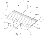
- Fig. 1 1 and 2 each show an embodiment of a device 10 for ionizing air with an ion emitter 12 and an emitter carrier 14.
- the emitter carrier 14 is designed as a profile 16.
- a profile cross-section 17 of the profile 16 can be seen on an end face 26 of the profile 16.
- a mold line 18 is arranged perpendicular to the profile cross-section 17.
- the profile 16 also has a longitudinal profile axis 20 arranged perpendicular to the mold line 18 and intersecting the profile 16.
- the end face 26 is preferably arranged parallel to the longitudinal profile axis 20.
- the profile 16 is preferably designed as a laminar profile, the profile cross-section 17 of which is designed such that when air flows around it in a designated flow direction 34, a preferably exclusively laminar flow is formed.
- the profile longitudinal axis 20 is arranged along the flow direction 34 provided for the profile 16. Along the profile longitudinal axis 20, the profile 16 is accordingly designed to be particularly streamlined.
- the profile cross-section 17 has a typical teardrop shape. As can be seen from Fig. 1 u. 2, in particular on the front side 26 of the respective profile 16, in these embodiments of the device 10 the profile cross-section 17 is designed as a wing cross-section 21, as is used, for example, in the wings of aircraft.
- the ion emitter 12 is formed by two needle-shaped electrodes 22 which are arranged on the same emitter carrier 14.
- the needle-shaped electrodes 22 have a small Flow resistance and can be designed to be easy to manufacture and assemble.
- the ion emitter 12 is arranged on a rear edge 23 of the wing cross-section 21.
- the electrodes 22 are aligned in the intended flow direction 34.
- the ion emitter 12 is arranged on the profile 10 so that the device 10 is designed as a spatially connected assembly. In particular, the integration and assembly of the device 10 can be made easier as a result.
- Fig. 1 In contrast to the embodiment of the Fig. 2 , indicates that Fig. 1 shown profile 16 has a recess 24 in which the ion emitter 12 is arranged.
- the recess 24 is arranged on the rear edge 23 of the profile 16 and has a parabolic recess contour 25.
- Fig. 1 It is clearly visible that the length of the device 10 along the profile longitudinal axis 20 can be reduced by arranging the ion emitter 12 in the recess 24. This makes it easier to install the device 10, particularly in an existing flow channel 30.
- Fig. 1 also shows that the two electrodes 22 of the ion emitter 12 are arranged in different end regions 38 of the recess 24. A typical distance 40 between the electrodes is approximately 20 mm.
- the recess 24 completely intersects the profile 16 perpendicular to a surface spanned by the profile longitudinal axis 20 and the mold line 18, so that the electrodes 22 can be flowed onto from both sides with respect to this surface.
- a circuit board 42 for supplying voltage to the ion emitter 12 is arranged in the emitter carrier 14, in particular in the profile 16, a circuit board 42 for supplying voltage to the ion emitter 12 is arranged.
- a Fig. 2 A plug and/or clip connection (not shown) may be provided.
- the circuit board 42 may have several layers. Different electrical potentials are preferably carried on different layers of the circuit board 42. This prevents the voltage from jumping at the relatively high voltages present at the ion emitter 12.
- the ion emitter 12 is arranged directly on the circuit board 42.
- each of the electrodes 22 is arranged on a conductor track arranged on the circuit board 42.
- the circuit board 42 is typically equipped with the electrodes 22 in an automated manner.
- the profile 16 has an electrical connector 44 on at least one of the end faces 26 intersecting the mold line 18.
- the connector 44 allows the emitter carrier 14 to be easily connected to a connection element during or after the emitter carrier 14 is arranged in the flow channel 30.
- the connector 44 can be designed to be lockable.
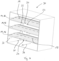
- the Fig. 3-8 show various embodiments of the flow channel 30, in which different embodiments of the device 10 for ionizing air are arranged.
- the flow channel 30 of each of the embodiments has a channel longitudinal axis 32.
- the flow direction 34 of the respective flow channel 30 is aligned along the channel longitudinal axis 32.
- the devices 10 are arranged in the respective flow channel 30 in such a way that the flow direction 34 present in the respective flow channel coincides with the Fig. 1
- the profile 16 of the at least one emitter carrier 14 is arranged in the flow channel 30 such that the respective shape line 18 is arranged perpendicular to the channel longitudinal axis 32.
- the profile longitudinal axis 20 is arranged parallel to the channel longitudinal axis 32.
- the emitter carriers 14 are designed in accordance with the emitter carrier 14 of the Fig. 1
- the device shown in Fig. 3 The embodiment shown has three of the emitter carriers 14.
- Each of the emitter carriers 14 can have more than one pair of electrodes 22 and thus several ion emitters 12.
- the emitter carriers 14 are arranged parallel to each other in this embodiment. Accordingly, the profile longitudinal axes 20 and the - straight - shape lines of the emitter carriers 14 are each arranged parallel to each other. Accordingly, the Fig. 3
- the flow channel 30 shown has a rectangular flow channel cross-section with a relatively large cross-sectional area.
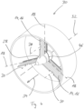
- the examples of the Fig. 4-6 show an alternative arrangement in which the emitter carriers 14 are arranged in a star shape around a central connecting line 28.
- the emitter carriers 14 are preferably arranged such that the profile longitudinal axes 20 of the emitter carriers 14 are parallel to one another and the - preferably straight - shape lines 18 are arranged with an angular offset 46 to one another.
- the connecting line 28 comprises in particular the voltage supply of the ion emitters 12 arranged on the emitter carriers 14.
- the device 10 is arranged in a flow channel section which can be inserted into the flow channel 30 for assembly along the channel longitudinal axis 32.
- the device 10 arranged in the flow channel 30 can, for example, have three or four emitter carriers 14.
- Fig. 6 shows an embodiment in which the profile longitudinal axes 20 and the channel longitudinal axis 32 each enclose an angle of attack 36 of greater than 0°.
- a swirl can be generated in the air flow.
- the angle of attack 36 can be designed to be variable and thus adjustable. With such an arrangement of the emitter carriers 14, the air flow in the flow channel 30 can be at least partially regulated.
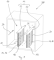
- the embodiment of the Fig. 7 has two emitter carriers 14 arranged parallel to each other. In contrast to the Fig. 3 However, in the embodiment shown, these emitter carriers 14 are not as shown in Fig. 1 Rather, the Fig. 7 The emitter carrier 14 shown has no recess 24. In addition, the two Electrodes 22 of the ion emitter 12 are arranged on different emitter carriers 14. Such a solution can be particularly useful if the flow channel 30 has a rectangular flow channel cross-section but a smaller cross-sectional area than the Fig. 3 shown flow channel 30. To mount this flow channel 30, the emitter carriers 14 can be introduced into the flow channel 30, for example, through an opening arranged laterally in the flow channel 30.
- Fig. 1-7 The profiles 16 shown each have a straight form line 18, the embodiment of the Fig. 8 that the shape line 18 can be curved and in particular circular. The shape of the profile 16 can thus be adapted in particular to a circular flow channel cross-section with a relatively large cross-sectional area.
- Fig. 8 The profile 16 shown can also have the wing cross-section 21 shown in the other figures.
- the device 10 of the Fig. 8 The embodiment shown can also have two or more ion emitters 12.
- the connecting line 28 is arranged laterally.
Landscapes
- Health & Medical Sciences (AREA)
- Engineering & Computer Science (AREA)
- Veterinary Medicine (AREA)
- Animal Behavior & Ethology (AREA)
- General Health & Medical Sciences (AREA)
- Public Health (AREA)
- Life Sciences & Earth Sciences (AREA)
- Chemical & Material Sciences (AREA)
- Epidemiology (AREA)
- Combustion & Propulsion (AREA)
- Mechanical Engineering (AREA)
- General Engineering & Computer Science (AREA)
- Elimination Of Static Electricity (AREA)
Applications Claiming Priority (1)
| Application Number | Priority Date | Filing Date | Title |
|---|---|---|---|
| DE102023113558.9A DE102023113558A1 (de) | 2023-05-24 | 2023-05-24 | Vorrichtung zur Ionisierung von Luft sowie Strömungskanal |
Publications (1)
| Publication Number | Publication Date |
|---|---|
| EP4477964A1 true EP4477964A1 (fr) | 2024-12-18 |
Family
ID=91072647
Family Applications (1)
| Application Number | Title | Priority Date | Filing Date |
|---|---|---|---|
| EP24175122.1A Pending EP4477964A1 (fr) | 2023-05-24 | 2024-05-10 | Dispositif d'ionisation d'air et canal d'écoulement |
Country Status (2)
| Country | Link |
|---|---|
| EP (1) | EP4477964A1 (fr) |
| DE (1) | DE102023113558A1 (fr) |
Citations (7)
| Publication number | Priority date | Publication date | Assignee | Title |
|---|---|---|---|---|
| DE10311255A1 (de) | 2002-09-18 | 2004-04-01 | T.E.M.! Technologische Entwicklungen Und Management Gmbh | Lufttransport- und/oder Aufbereitungsanlagen mit katalytisch beschichteten Oberflächen luftberührender Flächen |
| US7254006B2 (en) | 2001-08-07 | 2007-08-07 | Sharp Kabushiki Kaisha | Ion generating element and ion generator, air conditioning apparatus, cleaner and refrigerator containing the same |
| DE102008049280A1 (de) | 2008-09-26 | 2010-04-01 | Behr Gmbh & Co. Kg | Ionisationsvorrichtung |
| US8724286B2 (en) | 2007-08-23 | 2014-05-13 | 3M Innovative Properties Company | Ionizer having cleaning system |
| DE102017121192A1 (de) * | 2017-09-13 | 2019-03-14 | Valeo Klimasysteme Gmbh | Fahrzeugklimaanlagen-Auslasseinheit |
| US20220088263A1 (en) * | 2020-05-22 | 2022-03-24 | Delta T, Llc | Fan for improving air quality |
| DE102022104843A1 (de) | 2022-03-01 | 2023-09-07 | Vientum GmbH | Verfahren zur Herstellung eines Systems aus Lüftungskanalabschnitt und Gerät zur Luftionisierung, Gerät zur Luftionisierung, mit dem dieses Verfahren durchgeführt werden kann und System aus Lüftungskanalabschnitt und Gerät zur Luftionisierung |
Family Cites Families (2)
| Publication number | Priority date | Publication date | Assignee | Title |
|---|---|---|---|---|
| US8585980B2 (en) * | 2010-09-07 | 2013-11-19 | Puradigm, Llc | Enhanced photo-catalytic cells |
| DE202012100252U1 (de) * | 2012-01-25 | 2013-02-01 | Anima Metis Gmbh | Luftreinigungsvorrichtung |
-
2023
- 2023-05-24 DE DE102023113558.9A patent/DE102023113558A1/de active Pending
-
2024
- 2024-05-10 EP EP24175122.1A patent/EP4477964A1/fr active Pending
Patent Citations (7)
| Publication number | Priority date | Publication date | Assignee | Title |
|---|---|---|---|---|
| US7254006B2 (en) | 2001-08-07 | 2007-08-07 | Sharp Kabushiki Kaisha | Ion generating element and ion generator, air conditioning apparatus, cleaner and refrigerator containing the same |
| DE10311255A1 (de) | 2002-09-18 | 2004-04-01 | T.E.M.! Technologische Entwicklungen Und Management Gmbh | Lufttransport- und/oder Aufbereitungsanlagen mit katalytisch beschichteten Oberflächen luftberührender Flächen |
| US8724286B2 (en) | 2007-08-23 | 2014-05-13 | 3M Innovative Properties Company | Ionizer having cleaning system |
| DE102008049280A1 (de) | 2008-09-26 | 2010-04-01 | Behr Gmbh & Co. Kg | Ionisationsvorrichtung |
| DE102017121192A1 (de) * | 2017-09-13 | 2019-03-14 | Valeo Klimasysteme Gmbh | Fahrzeugklimaanlagen-Auslasseinheit |
| US20220088263A1 (en) * | 2020-05-22 | 2022-03-24 | Delta T, Llc | Fan for improving air quality |
| DE102022104843A1 (de) | 2022-03-01 | 2023-09-07 | Vientum GmbH | Verfahren zur Herstellung eines Systems aus Lüftungskanalabschnitt und Gerät zur Luftionisierung, Gerät zur Luftionisierung, mit dem dieses Verfahren durchgeführt werden kann und System aus Lüftungskanalabschnitt und Gerät zur Luftionisierung |
Also Published As
| Publication number | Publication date |
|---|---|
| DE102023113558A1 (de) | 2024-11-28 |
Similar Documents
| Publication | Publication Date | Title |
|---|---|---|
| EP2155398A1 (fr) | Procédé et dispositif pour extraire des impuretés d'un courant gazeux | |
| DE102011120720A1 (de) | Stützstift für einen elektrisch beheizbaren Wabenkörper | |
| DE102010055789A1 (de) | Stromschienenverbinder und Stromschienensystem mit mindestens zwei benachbarten Stromschienen und einem Stromschienenverbinder | |
| DE10018680A1 (de) | Kontaktschienenanordnung | |
| EP4477964A1 (fr) | Dispositif d'ionisation d'air et canal d'écoulement | |
| DE1187388B (de) | Schalldaempfer mit im Innern angeordneten Leitkoerpern | |
| EP3109530A1 (fr) | Dispositif de retenue d'un tuyau de gaz d'echappement de vehicule automobile | |
| DE102007051410A1 (de) | Trägerrohr für Deckenelemente | |
| DE202014105219U1 (de) | Erdungsschienenvorrichtung | |
| WO2006074888A1 (fr) | Procede et dispositif pour charger electrostatiquement et separer des particules difficiles a separer | |
| EP2982014B1 (fr) | Réalisation d'un type de protection pour appareils électriques et électroniques, en particulier pour armoires de distribution | |
| EP4177519B1 (fr) | Luminaire avec clip de retenue | |
| DE102004048488B4 (de) | Abgassystem mit einer Aggregationseinrichtung für eine Brennkraftmaschine | |
| DE102015218747A1 (de) | HV-Kabel-Anschlussanordnung | |
| DE102016107055B4 (de) | Potentialausgleichsklemme | |
| DE102022104843A1 (de) | Verfahren zur Herstellung eines Systems aus Lüftungskanalabschnitt und Gerät zur Luftionisierung, Gerät zur Luftionisierung, mit dem dieses Verfahren durchgeführt werden kann und System aus Lüftungskanalabschnitt und Gerät zur Luftionisierung | |
| EP3552711B1 (fr) | Élément filtrant électrostatique et dispositif d'aération pourvu d'un élément filtrant électrostatique | |
| DE1944973A1 (de) | Ausgedehntes Entladungssystem fuer elektrostatische Ausfuellvorrichtungen | |
| EP4000738B1 (fr) | Filtre de nettoyage d'un flux gazeux | |
| EP2204884B1 (fr) | Connecteur à vis de cage | |
| DE202013100223U1 (de) | Verbindungselement für eine Schleifleitung, Bausatz für eine Schleifleitung und Schleifleitung | |
| DE102016201928A1 (de) | Isolationsbauteil | |
| DE102017121199A1 (de) | Fahrzeugklimaanlagen-Auslasseinheit | |
| DE102017206606A1 (de) | Batteriemodul, Verfahren zu dessen Herstellung und Batterie | |
| DE102007052205B4 (de) | Luftauslassdüse für eine Trennstrahlanlage und Düsenstrang |
Legal Events
| Date | Code | Title | Description |
|---|---|---|---|
| PUAI | Public reference made under article 153(3) epc to a published international application that has entered the european phase |
Free format text: ORIGINAL CODE: 0009012 |
|
| STAA | Information on the status of an ep patent application or granted ep patent |
Free format text: STATUS: THE APPLICATION HAS BEEN PUBLISHED |
|
| AK | Designated contracting states |
Kind code of ref document: A1 Designated state(s): AL AT BE BG CH CY CZ DE DK EE ES FI FR GB GR HR HU IE IS IT LI LT LU LV MC ME MK MT NL NO PL PT RO RS SE SI SK SM TR |
|
| STAA | Information on the status of an ep patent application or granted ep patent |
Free format text: STATUS: REQUEST FOR EXAMINATION WAS MADE |
|
| 17P | Request for examination filed |
Effective date: 20250214 |