EP4479762B1 - Charge de courant autonome d'un système de bobine d'électro-aimant rm supraconducteur refroidi à sec - Google Patents
Charge de courant autonome d'un système de bobine d'électro-aimant rm supraconducteur refroidi à sec Download PDFInfo
- Publication number
- EP4479762B1 EP4479762B1 EP23725141.8A EP23725141A EP4479762B1 EP 4479762 B1 EP4479762 B1 EP 4479762B1 EP 23725141 A EP23725141 A EP 23725141A EP 4479762 B1 EP4479762 B1 EP 4479762B1
- Authority
- EP
- European Patent Office
- Prior art keywords
- coil system
- magnet coil
- magnet
- charging
- current
- Prior art date
- Legal status (The legal status is an assumption and is not a legal conclusion. Google has not performed a legal analysis and makes no representation as to the accuracy of the status listed.)
- Active
Links
Images


Classifications
-
- G—PHYSICS
- G01—MEASURING; TESTING
- G01R—MEASURING ELECTRIC VARIABLES; MEASURING MAGNETIC VARIABLES
- G01R33/00—Arrangements or instruments for measuring magnetic variables
- G01R33/20—Arrangements or instruments for measuring magnetic variables involving magnetic resonance
- G01R33/28—Details of apparatus provided for in groups G01R33/44 - G01R33/64
- G01R33/38—Systems for generation, homogenisation or stabilisation of the main or gradient magnetic field
- G01R33/3804—Additional hardware for cooling or heating of the magnet assembly, for housing a cooled or heated part of the magnet assembly or for temperature control of the magnet assembly
-
- G—PHYSICS
- G01—MEASURING; TESTING
- G01R—MEASURING ELECTRIC VARIABLES; MEASURING MAGNETIC VARIABLES
- G01R33/00—Arrangements or instruments for measuring magnetic variables
- G01R33/20—Arrangements or instruments for measuring magnetic variables involving magnetic resonance
- G01R33/28—Details of apparatus provided for in groups G01R33/44 - G01R33/64
- G01R33/38—Systems for generation, homogenisation or stabilisation of the main or gradient magnetic field
- G01R33/381—Systems for generation, homogenisation or stabilisation of the main or gradient magnetic field using electromagnets
- G01R33/3815—Systems for generation, homogenisation or stabilisation of the main or gradient magnetic field using electromagnets with superconducting coils, e.g. power supply therefor
-
- H—ELECTRICITY
- H01—ELECTRIC ELEMENTS
- H01F—MAGNETS; INDUCTANCES; TRANSFORMERS; SELECTION OF MATERIALS FOR THEIR MAGNETIC PROPERTIES
- H01F6/00—Superconducting magnets; Superconducting coils
- H01F6/02—Quenching; Protection arrangements during quenching
-
- H—ELECTRICITY
- H01—ELECTRIC ELEMENTS
- H01F—MAGNETS; INDUCTANCES; TRANSFORMERS; SELECTION OF MATERIALS FOR THEIR MAGNETIC PROPERTIES
- H01F6/00—Superconducting magnets; Superconducting coils
- H01F6/04—Cooling
Definitions
- Nuclear magnetic resonance is a powerful instrumental analytical technique, particularly suitable for determining the chemical composition of samples. Radiofrequency pulses are radiated into the sample, which is placed in a strong static magnetic field, and the sample's electromagnetic response is measured.
- the strong and, in NMR, particularly homogeneous static magnetic field is often generated using superconducting magnet systems, which, during measurement, must be cooled to very low cryogenic temperatures close to absolute zero, usually with the aid of liquid helium as a cryogenic fluid.
- Such superconducting magnet systems are often also equipped with active cooling. These systems then usually no longer have a fluid tank in which the magnets are directly surrounded by cryogenic fluid. Instead, the coils of the magnet systems are arranged in a vacuum vessel and are therefore "dry”—i.e., cryogen-free—during MR measurement mode. Radiation shields surrounding the vacuum vessel, and sometimes also the magnet systems themselves, are cooled directly by an active cooler, e.g., a pulse tube cooler or a Gifford-MacMahon cooler.
- an active cooler e.g., a pulse tube cooler or a Gifford-MacMahon cooler.
- the US 8 729 894 B2 discloses a magnet system for MRI, comprising a container with liquid cryogen therein, and a superconducting magnet within the container, wherein the container is configured to be removably connected to a vacuum pump, which in turn is configured to pump cryogen from the container to reduce a pressure level within the container during ramping of the superconducting magnet to a pumped-down pressure level and to increase the pressure level from the pumped-down pressure level to a normal operating pressure level during normal magnet operation.
- Reference [2] further describes a method for loading the magnet, wherein during so-called ramping, the container with the magnet can be evacuated. A cold head is arranged in a neck tube without affecting the vacuum in the container. However, The cryostat contains liquid helium.
- reference [2] represents more remote prior art, as it is a "wet-cooled" coil system, which precludes autonomous operation.
- the displaceably mounted cold head is moved away from the object to be cooled by the increased gas pressure in the hollow volume, thereby reducing the thermal coupling between the cooling arm and the object to be cooled.
- this cryostat the heat load caused by a cooling arm can be reduced if the active cooling system fails, but the structural complexity is comparatively large due to the movable suspension of the cold head.
- due to the high gas pressure in the hollow volume a significant thermal coupling remains.
- the reference [1] cited at the beginning describes a cryostat arrangement with a vacuum vessel and a cooling object arranged within the vacuum vessel, which has a neck tube leading to the cooling object.
- a cooling arm of a cold head, around which a closed cavity is formed, is arranged in the neck tube.
- the cooling arm is fluid-tightly sealed with respect to the cooling object and is filled with cryogenic fluid during normal operation.
- the cryogen in the neck tube can be evaporated for cooling under vacuum and, in particular, pumped out in the event of a cooling function failure in order to thermally decouple the cold head from the vacuum vessel.
- Such a cryostat can be used to carry out the generic method with the feature complexes defined at the beginning.
- reference [1] does not even hint at the charging of a magnetic coil with electrical current, let alone describe it in detail.
- An MR apparatus for carrying out the method according to the invention described above is defined in claim 12 and is equipped with a superconductive MR magnet coil system arranged in a vacuum container, which is dry during MR measuring operation, i.e. cryogen-free, and with a cryostat for cooling the MR magnet coil system, which comprises a neck tube which leads through an outer jacket of the vacuum container to the MR magnet coil system wherein a cooling arm of a cold head is arranged at least partially in the neck tube, wherein a closed cavity is formed around the cooling arm, which is fluid-tightly sealed against the MR magnet coil system to be cooled and is at least partially filled with a cryogenic fluid during normal operation of the MR apparatus.
- a vacuum pump and a first shut-off valve are arranged outside the vacuum container in a vacuum line leading from the vacuum pump into the vacuum container, that a temperature sensor for measuring a current temperature T coil on the MR magnet coil system and a first pressure sensor for measuring a current pressure P is in the vacuum container are present, and that a control unit is configured to detect and compare the current temperature T coil on the MR magnet coil system with predetermined temperature setpoints, to detect and compare the current pressure P is in the vacuum container with predetermined pressure setpoints and to control a first shut-off valve, the vacuum pump, the cold head and the charging power supply.
- a cryostat suitable for carrying out the charging method according to the invention described above in conjunction with the cooling method disclosed in reference [7] contributes to solving the expanded problem of the invention in that a fluid line is provided which opens at one end into a cavity surrounding the cooling arm of the cold head and at the other end into a pressure vessel filled with a cryogenic fluid outside the neck tube, and in that a second pressure sensor is provided for measuring the current pressure P HR in the cavity.
- the compressor is deactivated and waited until the coil temperature T coil has reached the set temperature limit of T2 tov , i.e. the temperature for thermal overshoot. This takes up to one hour depending on the magnet system.
- T2 tov the compressor is reactivated and a fixed time is waited, e.g., approximately 20 seconds, to give the compressor time to start.
- the system switches to an operating state in which the cooling system is activated so that any evaporated helium from the neck tube can be reliquefied. This also occurs in the event of a sensor malfunction. If the magnet quenches in this state, the temperature T coil rises above a critical value, and the charging process must be reinitiated by bringing the coil temperature in the cryostat back to T coil ⁇ T1 ramp .
- Thermal overshoot is preferably part of the automatic charging process and shortens the time required to reach the "drift spec," i.e., the currents in the superconducting coil are stabilized to such an extent that the magnetic field no longer changes or changes only slightly.
- thermal overshoot occurs after each charging process. This serves to force a faster, more even current distribution in the superconducting filaments through the temperature increase, allowing the magnet to reach its drift spec more quickly (no more recoupling in the filaments).
- the target current is first set to the currently measured current and the voltage to 0V.
- the main heater and screening heater are also deactivated, short-circuiting the magnet.
- the current current is then recorded and the main current is set to 0A, thus removing it from the power cables. Once the current is at 0A, only the cooling system remains active.
- the pumpable helium volume is limited to a small amount (e.g., 1.5 liters) of liquid helium, pumping can only be performed for a certain time, after which helium must be reliquefied. Once the pumping time defined in the loading script is exceeded, helium must be liquefied.
- the above-mentioned process variants can alternatively or additionally be further developed by pumping out the liquid helium in the neck tube with the vacuum pump in a step (c0′′′) between steps (c) and (d), if necessary, for example in the event of a cold head failure, in order to cool the MR magnet coil system.
- a particularly preferred class of embodiments of the inventive The method is therefore characterized in that the autonomous electrical charging process of the superconducting MR magnet coil system is automatically controlled by means of an electronic control unit, wherein the control unit is configured to record and compare the current temperature T coil on the MR magnet coil system or up to T istshield on the radiation shield with predetermined temperature setpoints, to record and compare the electrical current I coil currently flowing in the MR magnet coil system with predetermined current setpoints and, if necessary, to control valves, a charging power supply, a vacuum pump and functional units of the cold head.
- the measurement of P HR is used to monitor the pressure during the initial purging of the neck tube with He.
- the neck tube is alternately emptied via V2 and filled with helium via V1 using the vacuum pump, preferably a diaphragm pump when using a two-stage pump, so that as few foreign gases as possible are present in the neck tube before cooling.
- Vacuum pump 20 comprises a turbomolecular pump 20a with a backing pump 20b (e.g., a diaphragm pump).
- the vacuum pump 20 is connected to the vacuum vessel 11 via a vacuum line 22 and a first shut-off valve 21 (shut-off valve V3).
- a temperature sensor 23 is provided on the MR magnet coil system 12 for measuring a current temperature T coil on the MR magnet coil system 12.
- a control unit 40 detects and compares the current temperature T coil on the MR magnet coil system 12 with predetermined temperature setpoints. Furthermore, the control unit 40 detects and compares the current pressure P actual in the vacuum vessel 11 with predetermined pressure setpoints.
- the control unit 40 is further configured to control the first shut-off valve 21, the vacuum pump 20, and the compressor 13a of the cold head 17.
- an automatic current charging program is initiated after initiating a suitable cooling process.
- the charging current is supplied to the MR magnet coil system 12 from a charging power supply 50 via current rods 51 .
- the control unit 40 includes a measuring unit, a control unit, and a processor unit. Temperature sensors 23 and 56 are connected to the measuring unit, which measure the current temperature T coil and T istshield on the MR magnet coil system. 12 or at the radiation shield 55. Furthermore, the pressure sensor 24, which measures the current pressure P in the vacuum vessel 11, is connected to the measuring unit. The control unit is connected to the first shut-off valve 21, which the control unit can open and close. Furthermore, the control unit is connected to the vacuum pump 20 and the cold head 17 (or the compressor 13a), which the control unit can activate and deactivate. The processor unit is arranged between the measuring unit and the control unit. The processor unit compares the recorded parameters of the temperature sensor 23 and the pressure sensor 24 with the target parameters. This data is processed by the processor unit and used to control the cold head 17, the vacuum pump 20, the shut-off valve 21, and in particular the charging power supply 50.
- the current pressure P HR in cavity 18 can be measured via a second pressure sensor 25, which is connected to a connection 28 leading from a helium supply 29 into the cavity 18 of the cryostat 13.
- the second pressure sensor 25 is also connected to the measuring unit of the processor unit.
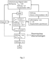
- Fig. 2 The basic sequence of the charging method according to the invention for embodiments with thermal overshoot and with only one valve is shown in Fig. 2 shown as a flow chart.
- the sequence of the charging method according to the invention can comprise the following steps in the 1-valve variant: After the cooling process (a1) of the magnet has been completed and the cooling is still on, the charging process can be initiated by starting the current charging program (a2), which can also be started by a non-expert by simply pressing a corresponding switch.
- the program runs through the process by first measuring (b1) the current temperature T coil and, if applicable, T istshield . When the temperatures have reached the target value at which the MR magnet coil system 12 and the HTS current rods are superconducting and can be charged, in step (b2) the charging current is supplied to the MR magnet coil system 12 and the MR magnet coil system 12 is charged with electrical current.
- the target current is set in steps according to a charging plan adapted to the magnet. Once the measured current is close to the respective target current, the next step is set. The charging voltage is set according to the charging plan based on the measured current. Finally, the target current I1 target is reached. As soon as I1 target is reached, the charging power supply 50 automatically stabilizes the I1 target by lowering the charging voltage to 0V (switching from voltage to current regulation).
- the temperatures T coil and T istshield are continuously monitored, as are the functioning of the cooling system and the necessary monitoring sensors.
- the charging process is interrupted and a transition to "Parking" is initiated.
- the target current is first set to the currently measured current and the voltage to 0 V.
- the main heater 52 and the screening heater 53 are also deactivated. Current is removed from the current rods 51, and cooling continues until the target temperatures are reached again. Then, the process continues with step (b1).
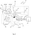
- Fig. 4 shows schematically a particularly simple embodiment of a magnetic resonance apparatus 10 (MR apparatus) with three valves for carrying out the auto-cooling method according to the invention.
- MR apparatus magnetic resonance apparatus 10
- the temperature sensor 23 for measuring a current temperature T coil is present on the MR magnet coil system 12.
- the control unit 40 (not shown here) detects and compares the current temperature T coil at the MR solenoid system 12 with predetermined temperature setpoints. Furthermore, the control unit 40 detects and compares the current pressure P actual in the vacuum vessel 11 with predetermined pressure setpoints.
- the control unit 40 is further configured to control the first shut-off valve 21, the vacuum pump 20, and the compressor 13a of the cold head 17.
- the control unit 40 includes the measuring unit, the control unit, and the processor unit.
- the temperature sensor 23, which measures the current temperature T coil at the MR solenoid system 12, is connected to the measuring unit.
- the first pressure sensor 24, which measures the current pressure P actual in the vacuum vessel 11, is connected to the measuring unit.
- the second pressure sensor 25, which measures the current pressure P HR in the neck tube 14, is connected to the measuring unit.
- the control unit is connected to the first shut-off valve 21, the second shut-off valve 27, and a third shut-off valve 30 (shut-off valve V1), which the control unit can open and close.
- Shut-off valve 30 is integrated into connection 28, which connects the helium supply 29 and the neck tube 14. Furthermore, the control unit is connected to the vacuum pump 20 and, via the compressor 13a, to the cold head 17, which can activate and deactivate the control unit.
- the processor unit is arranged between the measuring unit and the control unit. The processor unit compares the recorded parameters of the temperature sensor 23, the pressure sensor 24, and the pressure sensor 25 with the target parameters. This data is processed by the processor unit and used to control the cold head 17, the vacuum pump 20, the shut-off valves 21, 27, 30 and the charging power supply 50.
- the charging current is supplied to the MR magnet coil system 12 from a charging power supply 50 via current rods 51. Also shown here is a radiation shield 55, which may be equipped with a temperature sensor (again not specifically shown here).
- Fig. 5 shown as a flow chart.
- the sequence of the charging method according to the invention can comprise the following steps in the 3-valve variant: After the magnet's cooling process (a1) has been completed and the cooling system is switched on, the charging process can be initiated by starting the current charging program (a2), which can also be started by a non-expert by simply pressing a switch.
- the program runs the procedure by first measuring (b1) the current temperature T coil and, if applicable, T istshield . When the temperatures have reached the target value, above which the MR magnet coil system 12 and the HTS current rods are superconducting and can be charged, the charging current is supplied to the MR magnet coil system 12 in step (b2), and the MR magnet coil system 12 is charged with electrical current.
- the target current is adjusted in steps according to a charging plan adapted to the magnet.
- the next step is set.
- the charging voltage is adjusted according to the charging plan based on the measured current.
- the target current I1 target is reached. Once I1 target is reached, the charging power supply automatically stabilizes the I 1target by lowering the charging voltage to 0V (switching from voltage to current regulation).
- the temperatures T coil and T istshield are continuously monitored, as are the functioning of the cooling system and the necessary monitoring sensors.
- the charging process is interrupted and a transition to "Parking" is initiated.
- the target current is first set to the currently measured current and the voltage to 0 V.
- the main heater 52 and the screening heater 53 are also deactivated. Current is removed from the current rods, and cooling continues until the target temperatures are reached again. Then, the process continues with step (b1).
- the electrical current I coil currently flowing in the MR magnet coil system 12 is measured and compared with a predeterminable first current target value I 1target at which the MR magnet coil system 12 generates a desired magnetic field strength.
- the vacuum pump 20 is activated in intermediate steps (c0') and (c0") and the first shut-off valve 27 is opened so that liquid helium is pumped out of the neck tube. Charging can continue during pumping.
- thermal overshoot is addressed in steps (d1) by stopping cooling and (d2) monitoring the temperature.
- the magnet is then at Spec, and the current loading program is terminated in step (e).
- Fig. 6 a schematic flow diagram of the autonomous charging method according to the invention with the method steps according to the claims for embodiments with three valves is shown.
- Fig. 7 shows the structural diagram of a device for the autonomous electrical charging of the superconducting MR magnet coil system 12 of an MR apparatus 10 according to the invention, with a schematically illustrated coil system comprising a main coil 52 with a main switch 52' and a main heater 52" as well as a shield coil 53 with a shield switch 53' and a shield heater 53", with a charging power supply 50, with current rods 51, with a pump unit which has one or more vacuum pumps 20, and with a control unit 40 for controlling the charging process.
- the magnetic charger 50 is controlled via an Ethernet interface.
- the main switch 52' To charge the main coil 52, the main switch 52' must be opened, which is accomplished by heating a portion of the main coil 52 by the main heater 52". The heated portion thus loses superconductivity, and the main switch 52' is open. Accordingly, the main switch 52' is closed when the charging process is complete to short-circuit the superconducting main coil 52. Even if the charging process is interrupted, e.g., if a predetermined coil temperature or shield temperature is exceeded, the main switch 52' is closed before the current is drawn from the current rods.
- the shield coil 53 serves to compensate for external field disturbances. During the charging/discharging process, the shield coil 53 would become inductively charged to the point of quenching. To prevent this, the shield coil 53 is opened during charging and discharging via the shield switch 53', which is achieved by heating the shield heater 53".
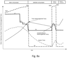
- Fig. 8a schematically shows the time sequence for the process variant "Parking when a maximum specified radiation shield temperature is reached" .
- the thick dashed curve shows the charging current, while the solid curve represents the charging voltage.
- the thin dashed line represents the radiation shield temperature T istshield , and the dotted line represents the coil temperature T coil .
- the coil temperature T ramp is used as the interruption ("parking") criterion.
- the cooling process takes place during The charge interruption without pumping out the helium in the neck tube.
- This variant is preferred for smaller magnets ( ⁇ 9T).
- Fig. 9 shows a schematic time diagram for a process variant of the auto-loading process according to the invention with multiple thermal overshooting .
- the thermal overshoot variant of the process is carried out.
- several thermal overshoots - here a total of four - are run through.
- the coil temperature T coil is increased in each case to the predetermined second temperature setpoint T2 tov ⁇ Tc, at which the superconducting current carrying capacity of the MR magnet coil system 12 is reduced to a desired lower value without the superconductivity in the magnet coil system 12 exceeding the critical transition temperature Tc at the transition from the normal conducting to the superconducting state and completely collapsing.
- This desired maximum temperature T2 tov is close to the critical transition temperature Tc, but with a safety margin, usually in the order of magnitude of approximately 100 mK.
- the superconductor of the MR magnet coil system 12 With each thermal overshoot cycle, the superconductor of the MR magnet coil system 12 is subjected to slightly greater load, ultimately leading to an optimized current distribution in the superconducting filaments.
- the specified drift of the MR magnet coil system 12 is achieved much faster than, for example, with bath-cooled magnet systems or with systems without thermal overshoot.
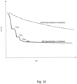
- Fig. 10 the drift behavior of an MR magnet coil system 12 after charging with and without thermal overshoot is shown: After charging a superconducting magnet in persistent mode, a temporal decay of the magnetic field typically begins. This can usually be explained by recoupling in the superconducting filaments. Only then does the conductor- and joint-induced drift behavior appear, with typical values of less than 0.05 ppm/h. However, this "natural" decay can last for several days or weeks, depending on the magnet type and conductor type. With a targeted thermal overshoot, this decay can be significantly shortened, and the typical long-term drift values can be achieved in just a few hours, depending on the magnet system. In the example shown in Fig. 10 In the curve shown with thermal overshoot, the multiple, in this example four, overshoot steps are clearly visible.
Landscapes
- Physics & Mathematics (AREA)
- Condensed Matter Physics & Semiconductors (AREA)
- General Physics & Mathematics (AREA)
- Electromagnetism (AREA)
- Engineering & Computer Science (AREA)
- Power Engineering (AREA)
- Magnetic Resonance Imaging Apparatus (AREA)
Claims (14)
- Procédé de fonctionnement d'un appareil à résonance magnétique(=« RM ») (10) comprenant un système de bobine magnétique RM supraconductrice (12) à sec (=« sans cryogène ») en mode de mesure RM, agencé dans un réservoir sous vide (11), et comprenant un cryostat (13) permettant de refroidir le système de bobine magnétique RM (12), lequel cryostat comprend un tube à collet (14) menant au système de bobine magnétique RM (12) en passant à travers une enveloppe extérieure (15) du réservoir sous vide (11), un bras de refroidissement (16) d'une tête froide (17) étant agencé au moins partiellement dans le tube à collet (14), et le système de bobine magnétique RM supraconductrice (12) étant refroidi à une température supraconductrice avant d'être chargé d'un courant de charge électrique,comprenant les étapes ci-dessous consistant à,en vue d'une charge électrique autonome du système de bobine magnétique RM supraconductrice (12) :(a1) lancer une opération de refroidissement du système de bobine magnétique RM supraconductrice (12) ;(a2) lancer un programme de charge de courant automatique pour le système de bobine magnétique RM supraconductrice (12) ;(b1) mesurer la température actuelle Tcoil au niveau du système de bobine magnétique RM (12) et comparer Tcoil avec une première valeur de consigne de température T1ramp prédéfinissable à partir de laquelle le système de bobine magnétique RM (12) est supraconducteur et doit être chargé, et mesurer la température actuelle Tistshield au niveau d'un bouclier de rayonnement (55) et comparer Tistshield avec une première valeur de consigne de température Tshield prédéfinissable,(b2) si Tcoil ≤ T1ramp et si Tistshield ≤ Tshield :
fournir un courant de charge au système de bobine magnétique RM (12) et charger le système de bobine magnétique RM (12) avec un courant électrique ;(c) mesurer le courant électrique Icoil circulant actuellement dans le système de bobine magnétique RM (12) et comparer Icoil avec une première valeur de consigne de courant I1target prédéfinissable pour laquelle le système de bobine magnétique RM (12) produit une intensité de champ magnétique souhaitée ;(d) répéter les étapes (b1), (b2) et (c) jusqu'à ce que Icoil = I1target,(e) désactiver l'alimentation en courant dans le système de bobine magnétique RM (12) et arrêter le programme de charge de courant automatique. - Procédé selon la revendication 1, caractérisé en ce que les étapes intermédiaires ci-dessous sont mises en œuvre entre l'étape (d) et l'étape (e) :(d1) dès que Icoil = I1target : arrêter l'opération de refroidissement du système de bobine magnétique RM supraconductrice (12) ;(d2) mesurer la température actuelle Tcoil au niveau du système de bobine magnétique RM (12) et comparer Tcoil avec une deuxième valeur de consigne de température prédéfinissable T2tov ≤ Tc pour laquelle la capacité supraconductrice de charge de courant du système de bobine magnétique RM (12) est réduite à une valeur inférieure prédéfinissable sans que la supraconductivité au sein du système de bobine magnétique (12) dépasse la température de transition critique Tc lors de la transition de l'état de conduction normal à l'état supraconducteur et s'effondre complètement ;(d3) dès que Tcoil = T2tov : arrêter l'opération de refroidissement du système de bobine magnétique RM supraconductrice (12) ;
- Procédé selon la revendication 2, caractérisé en ce que les étapes (d1) à (d3) sont répétées plusieurs fois après avoir atteint le critère Tcoil = T2tov à l'étape (d3).
- Procédé selon l'une quelconque des revendications précédentes, caractérisé en ce que si Tcoil > T1ramp à l'étape (b2), la charge du système de bobine magnétique MR (12) avec un courant électrique est interrompue et l'opération de refroidissement est poursuivie jusqu'à ce que Tcoil ≤ T1ramp ; puis le procédé reprend à l'étape (b1).
- Procédé selon l'une quelconque des revendications précédentes, caractérisé en ce qu'autour du bras de refroidissement (16) est formée une cavité fermée (18) qui est rendue étanche aux fluides par rapport au système de bobine magnétique RM (12) à refroidir et qui est remplie au moins partiellement d'hélium liquide (19) en fonctionnement normal de l'appareil RM (10), en ce que le tube à collet (14) est relié par l'intermédiaire d'une première vanne V1 (30) à une alimentation en gaz hélium (29) à travers laquelle, d'une part, du gaz hélium peut être introduit pour être liquéfié au niveau du bras de refroidissement et, d'autre part, en ce que l'hélium est pompé dans le tube à collet (14) pendant les étapes (c) et (d), grâce aux étapes ci-dessous consistant à(c0') mesurer le courant électrique Icoil circulant actuellement dans le système de bobine magnétique RM (12) et comparer Icoil avec une deuxième valeur de consigne de courant prédéfinissable I2pump ≤ I1target à partir de laquelle l'hélium doit être pompé dans le tube à collet (14) ; et(c0") dès que Icoil ≥ I2pump : activer une pompe à vide (20) agencée à l'extérieur du réservoir sous vide (11), ouvrir la première vanne d'arrêt (27) dans une conduite de pompage (26) menant de la pompe à vide (20) jusque dans le tube à collet (14) afin de pomper du gaz hélium hors du tube à collet avec la pompe à vide (20).
- Procédé selon la revendication 5, caractérisé en ce que la conduite d'alimentation (26) menant au tube à collet (14) est reliée à la pompe à vide (20) par l'intermédiaire d'une vanne V3 (30) supplémentaire, et en ce que de l'hélium est acheminé et liquéfié dans le tube à collet (14) lors d'une étape (f).
- Procédé selon l'une quelconque des revendications précédentes, caractérisé en ce que si Tistshield > Tshield, la charge du système de bobine magnétique MR (12) avec un courant électrique lors de l'étape (b2) est interrompue et l'opération de refroidissement est poursuivie jusqu'à ce que Tistshield ≤ Tshield, puis le procédé reprend à l'étape (b1).
- Procédé selon l'une quelconque des revendications précédentes, caractérisé en ce que les valeurs de consigne de température prédéfinissables T1ramp et T2tov ainsi que les valeurs de consigne de courant prédéfinissables I1target et I2pump sont sélectionnées parmi les plages de valeurs ci-dessous :


- Procédé selon l'une quelconque des revendications précédentes, caractérisé en ce que l'opération de charge électrique autonome du système de bobine magnétique RM supraconductrice (12) est régulé automatiquement au moyen d'une unité de contrôle électronique (40), l'unité de contrôle (40) étant configurée pour détecter et comparer la température actuelle Tcoil au niveau du système de bobine magnétique RM (12) avec des valeurs de consigne de température prédéfinies, pour détecter et comparer le courant électrique Icoil circulant actuellement dans le système de bobine magnétique RM (12) avec des valeurs de consigne de courant prédéfinies et, le cas échéant, pour commander des vannes (21 ; 27 ; 30), un appareil secteur de charge (50), une pompe à vide (20) et des unités fonctionnelles de la tête froide (17).
- Procédé selon la revendication 9, caractérisé en ce que l'unité de contrôle électronique (40) régule de manière complètement automatique l'opération de charge électrique autonome du système de bobine magnétique RM supraconductrice (12) au moyen d'un algorithme en tenant compte de diverses valeurs de mesure et divers paramètres en l'absence de personnel d'exploitation ou de surveillance, même pendant la nuit, en particulier pendant plusieurs jours, sans interruption temporelle, et en ce que, pendant l'opération de charge électrique autonome du système de bobine magnétique RM supraconductrice (12), l'unité de contrôle électronique (40) détecte automatiquement des changements d'état critiques et des perturbations du système de bobine magnétique RM supraconductrice (12) et du cryostat (13) permettant de refroidir le système de bobine magnétique RM (12), en particulier des températures, des courants et des valeurs de pression au sein du réservoir sous vide (11), et réagit à cela en utilisant une variante d'algorithme prédéfinie afin de continuer à réguler l'opération de charge électrique autonome et/ou en envoyant des messages ou des messages d'erreur, par exemple des messages électroniques, au personnel d'exploitation ou de surveillance.
- Procédé selon l'une quelconque des revendications 9 ou 10, caractérisé en ce que l'unité de contrôle électronique (40) a accès à au moins un algorithme permettant une décharge électrique autonome ou une décharge partielle du système de bobine magnétique RM supraconductrice (12) à partir d'un état chargé électriquement, et en ce que l'opération de décharge est régulée de manière complètement automatique grâce à l'unité de contrôle électronique (40) avec des conditions limites préajustables.
- Appareil à résonance magnétique(=« RM ») (10) permettant la mise en œuvre du procédé selon l'une quelconque des revendications 1 à 11, comprenant un système de bobine magnétique RM supraconductrice (12) à sec (=« sans cryogène ») en mode de mesure RM, agencé dans un réservoir sous vide (11), et un cryostat (13), permettant de refroidir le système de bobine magnétique RM (12), lequel cryostat comprend un tube à collet (14) menant au système de bobine magnétique RM (12) en passant à travers une enveloppe extérieure (15) du réservoir sous vide (11), un bras de refroidissement (16) d'une tête froide (17) étant agencé au moins partiellement dans le tube à collet (14), une cavité fermée (18), rendue étanche aux fluides par rapport au système de bobine magnétique RM (12) à refroidir et remplie au moins partiellement d'un fluide cryogénique (19) en fonctionnement normal de l'appareil RM (10), étant formée autour du bras de refroidissement (16), une pompe à vide (20) faisant partie de l'appareil RM (10) et une première vanne d'arrêt (21) étant agencées à l'extérieur du réservoir sous vide (11) dans une conduite sous vide (22) menant de la pompe à vide (20) jusqu'au réservoir sous vide (11), un capteur de température (23) permettant de mesurer une température actuelle Tcoil au niveau du système de bobine magnétique RM (12), un capteur de température (56) permettant de mesurer une température actuelle Tshield au niveau du bouclier de rayonnement (55) et un premier capteur de pression (24) permettant de mesurer une pression actuelle Pist étant présents dans le réservoir sous vide (11),
et comprenant une unité de contrôle selon la revendication 13. - Unité de contrôle (40) à utiliser dans un appareil RM (10) comprenant un système de bobine magnétique RM supraconductrice à sec en mode de mesure RM, agencé dans un réservoir sous vide, et comprenant un cryostat permettant de refroidir le système de bobine magnétique RM, lequel cryostat comprend un tube à collet menant au système de bobine magnétique RM en passant à travers une enveloppe extérieure du réservoir sous vide, un bras de refroidissement d'une tête froide étant agencé au moins partiellement dans le tube à collet, une cavité fermée, rendue étanche aux fluides par rapport au système de bobine magnétique RM à refroidir et remplie au moins partiellement d'un fluide cryogénique en mode normal de l'appareil RM, étant formée autour du bras de refroidissement, une pompe à vide faisant partie de l'appareil RM et une première vanne d'arrêt étant agencées à l'extérieur du réservoir sous vide dans une conduite sous vide menant de la pompe à vide jusque dans le réservoir sous vide, un capteur de température permettant de mesurer une température actuelle Tcoil au niveau du système de bobine magnétique RM, un capteur de température permettant de mesurer une température actuelle Tshield au niveau du bouclier de rayonnement et un premier capteur de pression permettant de mesurer une pression actuelle Pist étant présents dans le réservoir sous vide.l'unité de contrôle (40) étant configurée pour mettre en œuvre le procédé selon l'une quelconque des revendications 1 à 11, l'unité de contrôle (40) comprenant un programme de charge de courant automatique et étant configurée pour détecter et comparer une température actuelle Tcoil au niveau du système de bobine magnétique RM (12) avec des valeurs de consigne de température prédéfinies, et pour détecter et comparer une pression actuelle Pist au sein du réservoir sous vide (11) avec des valeurs de consigne de pression prédéfinies, l'unité de contrôle (40) présentant une unité de mesure à laquelle sont raccordés - comme faisant partie de l'unité de mesure - un capteur de température (23) permettant de mesurer la température actuelle Tcoil au niveau du système de bobine magnétique RM (12) et un capteur de pression (24) permettant de mesurer la pression actuelle Pist au sein du réservoir sous vide (11),l'unité de contrôle (40) comprenant une unité de commande permettant d'ouvrir et de fermer la première vanne d'arrêt (21) afin d'activer et de désactiver la pompe à vide (20) et afin d'activer et de désactiver la tête froide (17).
- Unité de contrôle selon la revendication 13, une liaison (26) allant du tube à collet (14) jusqu'à la pompe à vide (20) étant présente dans l'appareil RM (10), caractérisée en ce que l'unité de contrôle (40) est configurée pour réguler la commande d'une vanne d'arrêt V2 (27) présente dans l'appareil RM (10) et menant à la pompe à vide (20), en ce qu'une liaison (28) allant d'une alimentation en hélium (29) jusqu'au tube à collet (14) est présente dans l'appareil RM (10), et en ce que l'unité de contrôle (40) est configurée pour réguler la commande de l'alimentation en He (29) par l'intermédiaire de la vanne (30).
Applications Claiming Priority (2)
| Application Number | Priority Date | Filing Date | Title |
|---|---|---|---|
| DE102022204476.2A DE102022204476A1 (de) | 2022-05-06 | 2022-05-06 | Autonome Strombeladung eines supraleitfähigen, trocken-gekühlten MR-Magnetspulensystems |
| PCT/EP2023/061698 WO2023213895A1 (fr) | 2022-05-06 | 2023-05-03 | Charge de courant autonome d'un système de bobine d'électro-aimant rm super-conducteur refroidi à sec |
Publications (2)
| Publication Number | Publication Date |
|---|---|
| EP4479762A1 EP4479762A1 (fr) | 2024-12-25 |
| EP4479762B1 true EP4479762B1 (fr) | 2025-07-02 |
Family
ID=86425992
Family Applications (1)
| Application Number | Title | Priority Date | Filing Date |
|---|---|---|---|
| EP23725141.8A Active EP4479762B1 (fr) | 2022-05-06 | 2023-05-03 | Charge de courant autonome d'un système de bobine d'électro-aimant rm supraconducteur refroidi à sec |
Country Status (6)
| Country | Link |
|---|---|
| US (1) | US20250314725A1 (fr) |
| EP (1) | EP4479762B1 (fr) |
| CN (1) | CN119156544A (fr) |
| DE (1) | DE102022204476A1 (fr) |
| HU (1) | HUE072907T2 (fr) |
| WO (1) | WO2023213895A1 (fr) |
Family Cites Families (10)
| Publication number | Priority date | Publication date | Assignee | Title |
|---|---|---|---|---|
| US7298602B2 (en) | 2003-11-26 | 2007-11-20 | Ge Medical System, Inc. | Automated superconducting magnet ramp-up system and method |
| US8729894B2 (en) | 2010-07-30 | 2014-05-20 | General Electric Company | System and method for operating a magnetic resonance imaging system during ramping |
| DE102014218773B4 (de) | 2014-09-18 | 2020-11-26 | Bruker Biospin Gmbh | Automatische thermische Entkopplung eines Kühlkopfs |
| DE102015215919B4 (de) | 2015-08-20 | 2017-06-22 | Bruker Biospin Gmbh | Verfahren und Vorrichtung zur Vorkühlung eines Kryostaten |
| CA2944129C (fr) * | 2015-10-16 | 2018-07-24 | Synaptive Medical (Barbados) Inc. | Systeme d'imagerie par resonnance magnetique capable de croissance de champ rapide |
| DE102016218000B3 (de) | 2016-09-20 | 2017-10-05 | Bruker Biospin Gmbh | Kryostatenanordnung mit einem Vakuumbehälter und einem zu kühlenden Objekt, mit evakuierbarem Hohlraum |
| CN107845474B (zh) | 2017-12-14 | 2019-10-25 | 安徽工业大学 | 一种用于金属软磁粉芯的绝缘全无机粘合剂及其使用方法 |
| CN108022711B (zh) | 2018-01-02 | 2020-06-12 | 中国科学院电工研究所 | 一种智能化磁共振全身成像超导磁体系统 |
| EP4141347A4 (fr) * | 2020-04-23 | 2023-10-25 | Sumitomo Heavy Industries, LTD. | Dispositif à aimant supraconducteur, machine de congélation cryogénique et procédé de refroidissement pour dispositif à aimant supraconducteur |
| DE102021206392A1 (de) | 2021-06-22 | 2022-12-22 | Bruker Biospin Gmbh | Autonomes Herunterkühlen eines supraleitfähigen, trocken-gekühlten MR-Magnetspulensystems |
-
2022
- 2022-05-06 DE DE102022204476.2A patent/DE102022204476A1/de active Pending
-
2023
- 2023-05-03 CN CN202380038810.3A patent/CN119156544A/zh active Pending
- 2023-05-03 WO PCT/EP2023/061698 patent/WO2023213895A1/fr not_active Ceased
- 2023-05-03 HU HUE23725141A patent/HUE072907T2/hu unknown
- 2023-05-03 US US18/863,493 patent/US20250314725A1/en active Pending
- 2023-05-03 EP EP23725141.8A patent/EP4479762B1/fr active Active
Also Published As
| Publication number | Publication date |
|---|---|
| EP4479762A1 (fr) | 2024-12-25 |
| US20250314725A1 (en) | 2025-10-09 |
| CN119156544A (zh) | 2024-12-17 |
| WO2023213895A1 (fr) | 2023-11-09 |
| HUE072907T2 (hu) | 2025-12-28 |
| DE102022204476A1 (de) | 2023-11-09 |
Similar Documents
| Publication | Publication Date | Title |
|---|---|---|
| EP3488451B1 (fr) | Dispositif et procédé permettant un fonctionnement surrefroidi d'un cryostat avec de faibles quantités de réfrigérant | |
| DE102013208631B3 (de) | Magnetresonanzvorrichtung mit einem Kühlsystem zu einer Kühlung einer supraleitenden Hauptmagnetspule sowie ein Verfahren zur Kühlung der supraleitenden Hauptmagnetspule | |
| DE3427601C2 (fr) | ||
| DE102011078608B4 (de) | Kryostatanordnung | |
| US9874618B2 (en) | Control system and method for a superconducting magnet | |
| EP3285032A1 (fr) | Système magnétique non-cryogénique pourvu d'un dissipateur thermique raccordé à un circuit de gaz d'un cryorefroidisseur | |
| DE4129522A1 (de) | Kaelte-regler | |
| DE69709498T2 (de) | Kühlverfahren und Stromversorgungsverfahren eines Supraleiters | |
| DE102022209941A1 (de) | Vorrichtung zum Transfer von flüssigem Helium, mit verringerten Transfer-Verlusten | |
| WO2007107240A1 (fr) | Cryostat muni d'un système de bobines magnétiques qui comprend une section LTS et une section HTS encapsulée | |
| DE102014222856B4 (de) | Kaltkopfanordnung und zugehöriges Betriebsverfahren | |
| EP4479762B1 (fr) | Charge de courant autonome d'un système de bobine d'électro-aimant rm supraconducteur refroidi à sec | |
| EP4109121B1 (fr) | Refroidissement autonome d'un système supraconducteur de bobine magnétique rm à refroidissement à sec | |
| DE102010028750B4 (de) | Verlustarme Kryostatenanordnung | |
| DE102015218019A1 (de) | Kryostat mit Magnetanordnung, die einen LTS-Bereich und einen HTS-Bereich umfasst | |
| EP3467852A1 (fr) | Dispositif magnétique pourvu de cryostat et de système de bobines magnétiques, d'accumulateurs de froid sur les alimentations en courant | |
| DE19604805C2 (de) | Anlage der Supraleitungstechnik mit einer indirekt zu kühlenden supraleitenden Einrichtung und einer Stromzuführungsvorrichtung | |
| EP4575352A1 (fr) | Dispositif et procédé de transfert d'hélium liquide dans un cryostat d'application | |
| DE1501734B2 (de) | Vorrichtung zum nachfuellen von fluessigem helium aus einem vorratsbehaelter in einen kryostaten | |
| EP4652469B1 (fr) | Dispositif de régulation de la pression dans un réservoir d'hélium d'un aimant rmn, comprenant deux capteurs de pression | |
| EP1470740A2 (fr) | Dispositif permettant d'echauffer des parties froides a masse thermique elevee | |
| EP4668295A1 (fr) | Dispositif de refroidissement pour refroidir un aimant supraconducteur | |
| DE102013213242A1 (de) | Spuleneinrichtung mit Spule und Kühlvorrichtung sowie Verfahren zur Kühlung einer Spule |
Legal Events
| Date | Code | Title | Description |
|---|---|---|---|
| STAA | Information on the status of an ep patent application or granted ep patent |
Free format text: STATUS: UNKNOWN |
|
| STAA | Information on the status of an ep patent application or granted ep patent |
Free format text: STATUS: THE INTERNATIONAL PUBLICATION HAS BEEN MADE |
|
| STAA | Information on the status of an ep patent application or granted ep patent |
Free format text: STATUS: EXAMINATION IS IN PROGRESS |
|
| PUAI | Public reference made under article 153(3) epc to a published international application that has entered the european phase |
Free format text: ORIGINAL CODE: 0009012 |
|
| 17P | Request for examination filed |
Effective date: 20240918 |
|
| AK | Designated contracting states |
Kind code of ref document: A1 Designated state(s): AL AT BE BG CH CY CZ DE DK EE ES FI FR GB GR HR HU IE IS IT LI LT LU LV MC ME MK MT NL NO PL PT RO RS SE SI SK SM TR |
|
| P01 | Opt-out of the competence of the unified patent court (upc) registered |
Free format text: CASE NUMBER: APP_204/2025 Effective date: 20250103 |
|
| GRAP | Despatch of communication of intention to grant a patent |
Free format text: ORIGINAL CODE: EPIDOSNIGR1 |
|
| STAA | Information on the status of an ep patent application or granted ep patent |
Free format text: STATUS: GRANT OF PATENT IS INTENDED |
|
| DAV | Request for validation of the european patent (deleted) | ||
| DAX | Request for extension of the european patent (deleted) | ||
| INTG | Intention to grant announced |
Effective date: 20250327 |
|
| GRAS | Grant fee paid |
Free format text: ORIGINAL CODE: EPIDOSNIGR3 |
|
| GRAA | (expected) grant |
Free format text: ORIGINAL CODE: 0009210 |
|
| STAA | Information on the status of an ep patent application or granted ep patent |
Free format text: STATUS: THE PATENT HAS BEEN GRANTED |
|
| AK | Designated contracting states |
Kind code of ref document: B1 Designated state(s): AL AT BE BG CH CY CZ DE DK EE ES FI FR GB GR HR HU IE IS IT LI LT LU LV MC ME MK MT NL NO PL PT RO RS SE SI SK SM TR |
|
| REG | Reference to a national code |
Ref country code: GB Ref legal event code: FG4D Free format text: NOT ENGLISH |
|
| REG | Reference to a national code |
Ref country code: CH Ref legal event code: EP |
|
| REG | Reference to a national code |
Ref country code: DE Ref legal event code: R096 Ref document number: 502023001283 Country of ref document: DE |
|
| REG | Reference to a national code |
Ref country code: IE Ref legal event code: FG4D Free format text: LANGUAGE OF EP DOCUMENT: GERMAN |
|
| REG | Reference to a national code |
Ref country code: NL Ref legal event code: FP |
|
| PG25 | Lapsed in a contracting state [announced via postgrant information from national office to epo] |
Ref country code: PT Free format text: LAPSE BECAUSE OF FAILURE TO SUBMIT A TRANSLATION OF THE DESCRIPTION OR TO PAY THE FEE WITHIN THE PRESCRIBED TIME-LIMIT Effective date: 20251103 |
|
| REG | Reference to a national code |
Ref country code: HU Ref legal event code: AG4A Ref document number: E072907 Country of ref document: HU |
|
| PG25 | Lapsed in a contracting state [announced via postgrant information from national office to epo] |
Ref country code: IS Free format text: LAPSE BECAUSE OF FAILURE TO SUBMIT A TRANSLATION OF THE DESCRIPTION OR TO PAY THE FEE WITHIN THE PRESCRIBED TIME-LIMIT Effective date: 20251102 |
|
| PG25 | Lapsed in a contracting state [announced via postgrant information from national office to epo] |
Ref country code: NO Free format text: LAPSE BECAUSE OF FAILURE TO SUBMIT A TRANSLATION OF THE DESCRIPTION OR TO PAY THE FEE WITHIN THE PRESCRIBED TIME-LIMIT Effective date: 20251002 |
|
| REG | Reference to a national code |
Ref country code: LT Ref legal event code: MG9D |
|
| PG25 | Lapsed in a contracting state [announced via postgrant information from national office to epo] |
Ref country code: FI Free format text: LAPSE BECAUSE OF FAILURE TO SUBMIT A TRANSLATION OF THE DESCRIPTION OR TO PAY THE FEE WITHIN THE PRESCRIBED TIME-LIMIT Effective date: 20250702 |
|
| PG25 | Lapsed in a contracting state [announced via postgrant information from national office to epo] |
Ref country code: HR Free format text: LAPSE BECAUSE OF FAILURE TO SUBMIT A TRANSLATION OF THE DESCRIPTION OR TO PAY THE FEE WITHIN THE PRESCRIBED TIME-LIMIT Effective date: 20250702 |
|
| PG25 | Lapsed in a contracting state [announced via postgrant information from national office to epo] |
Ref country code: GR Free format text: LAPSE BECAUSE OF FAILURE TO SUBMIT A TRANSLATION OF THE DESCRIPTION OR TO PAY THE FEE WITHIN THE PRESCRIBED TIME-LIMIT Effective date: 20251003 |
|
| PG25 | Lapsed in a contracting state [announced via postgrant information from national office to epo] |
Ref country code: CZ Free format text: LAPSE BECAUSE OF FAILURE TO SUBMIT A TRANSLATION OF THE DESCRIPTION OR TO PAY THE FEE WITHIN THE PRESCRIBED TIME-LIMIT Effective date: 20250702 Ref country code: SE Free format text: LAPSE BECAUSE OF FAILURE TO SUBMIT A TRANSLATION OF THE DESCRIPTION OR TO PAY THE FEE WITHIN THE PRESCRIBED TIME-LIMIT Effective date: 20250702 |
|
| PG25 | Lapsed in a contracting state [announced via postgrant information from national office to epo] |
Ref country code: LV Free format text: LAPSE BECAUSE OF FAILURE TO SUBMIT A TRANSLATION OF THE DESCRIPTION OR TO PAY THE FEE WITHIN THE PRESCRIBED TIME-LIMIT Effective date: 20250702 |
|
| PG25 | Lapsed in a contracting state [announced via postgrant information from national office to epo] |
Ref country code: PL Free format text: LAPSE BECAUSE OF FAILURE TO SUBMIT A TRANSLATION OF THE DESCRIPTION OR TO PAY THE FEE WITHIN THE PRESCRIBED TIME-LIMIT Effective date: 20250702 Ref country code: BG Free format text: LAPSE BECAUSE OF FAILURE TO SUBMIT A TRANSLATION OF THE DESCRIPTION OR TO PAY THE FEE WITHIN THE PRESCRIBED TIME-LIMIT Effective date: 20250702 |
|
| PG25 | Lapsed in a contracting state [announced via postgrant information from national office to epo] |
Ref country code: RS Free format text: LAPSE BECAUSE OF FAILURE TO SUBMIT A TRANSLATION OF THE DESCRIPTION OR TO PAY THE FEE WITHIN THE PRESCRIBED TIME-LIMIT Effective date: 20251002 |
|
| PG25 | Lapsed in a contracting state [announced via postgrant information from national office to epo] |
Ref country code: ES Free format text: LAPSE BECAUSE OF FAILURE TO SUBMIT A TRANSLATION OF THE DESCRIPTION OR TO PAY THE FEE WITHIN THE PRESCRIBED TIME-LIMIT Effective date: 20250702 |
|
| PG25 | Lapsed in a contracting state [announced via postgrant information from national office to epo] |
Ref country code: SM Free format text: LAPSE BECAUSE OF FAILURE TO SUBMIT A TRANSLATION OF THE DESCRIPTION OR TO PAY THE FEE WITHIN THE PRESCRIBED TIME-LIMIT Effective date: 20250702 |
|
| PG25 | Lapsed in a contracting state [announced via postgrant information from national office to epo] |
Ref country code: DK Free format text: LAPSE BECAUSE OF FAILURE TO SUBMIT A TRANSLATION OF THE DESCRIPTION OR TO PAY THE FEE WITHIN THE PRESCRIBED TIME-LIMIT Effective date: 20250702 |
|
| PG25 | Lapsed in a contracting state [announced via postgrant information from national office to epo] |
Ref country code: IT Free format text: LAPSE BECAUSE OF FAILURE TO SUBMIT A TRANSLATION OF THE DESCRIPTION OR TO PAY THE FEE WITHIN THE PRESCRIBED TIME-LIMIT Effective date: 20250702 |