EP3488451B1 - Dispositif et procédé permettant un fonctionnement surrefroidi d'un cryostat avec de faibles quantités de réfrigérant - Google Patents
Dispositif et procédé permettant un fonctionnement surrefroidi d'un cryostat avec de faibles quantités de réfrigérant Download PDFInfo
- Publication number
- EP3488451B1 EP3488451B1 EP17757758.2A EP17757758A EP3488451B1 EP 3488451 B1 EP3488451 B1 EP 3488451B1 EP 17757758 A EP17757758 A EP 17757758A EP 3488451 B1 EP3488451 B1 EP 3488451B1
- Authority
- EP
- European Patent Office
- Prior art keywords
- cavity
- cooled
- cryostat
- pump device
- cryostat arrangement
- Prior art date
- Legal status (The legal status is an assumption and is not a legal conclusion. Google has not performed a legal analysis and makes no representation as to the accuracy of the status listed.)
- Active
Links
Images



Classifications
-
- F—MECHANICAL ENGINEERING; LIGHTING; HEATING; WEAPONS; BLASTING
- F25—REFRIGERATION OR COOLING; COMBINED HEATING AND REFRIGERATION SYSTEMS; HEAT PUMP SYSTEMS; MANUFACTURE OR STORAGE OF ICE; LIQUEFACTION SOLIDIFICATION OF GASES
- F25D—REFRIGERATORS; COLD ROOMS; ICE-BOXES; COOLING OR FREEZING APPARATUS NOT OTHERWISE PROVIDED FOR
- F25D19/00—Arrangement or mounting of refrigeration units with respect to devices or objects to be refrigerated, e.g. infrared detectors
- F25D19/006—Thermal coupling structure or interface
-
- H—ELECTRICITY
- H01—ELECTRIC ELEMENTS
- H01F—MAGNETS; INDUCTANCES; TRANSFORMERS; SELECTION OF MATERIALS FOR THEIR MAGNETIC PROPERTIES
- H01F6/00—Superconducting magnets; Superconducting coils
- H01F6/04—Cooling
-
- F—MECHANICAL ENGINEERING; LIGHTING; HEATING; WEAPONS; BLASTING
- F17—STORING OR DISTRIBUTING GASES OR LIQUIDS
- F17C—VESSELS FOR CONTAINING OR STORING COMPRESSED, LIQUEFIED OR SOLIDIFIED GASES; FIXED-CAPACITY GAS-HOLDERS; FILLING VESSELS WITH, OR DISCHARGING FROM VESSELS, COMPRESSED, LIQUEFIED, OR SOLIDIFIED GASES
- F17C13/00—Details of vessels or of the filling or discharging of vessels
- F17C13/005—Details of vessels or of the filling or discharging of vessels for medium-size and small storage vessels not under pressure
- F17C13/006—Details of vessels or of the filling or discharging of vessels for medium-size and small storage vessels not under pressure for Dewar vessels or cryostats
- F17C13/007—Details of vessels or of the filling or discharging of vessels for medium-size and small storage vessels not under pressure for Dewar vessels or cryostats used for superconducting phenomena
-
- F—MECHANICAL ENGINEERING; LIGHTING; HEATING; WEAPONS; BLASTING
- F17—STORING OR DISTRIBUTING GASES OR LIQUIDS
- F17C—VESSELS FOR CONTAINING OR STORING COMPRESSED, LIQUEFIED OR SOLIDIFIED GASES; FIXED-CAPACITY GAS-HOLDERS; FILLING VESSELS WITH, OR DISCHARGING FROM VESSELS, COMPRESSED, LIQUEFIED, OR SOLIDIFIED GASES
- F17C3/00—Vessels not under pressure
- F17C3/02—Vessels not under pressure with provision for thermal insulation
- F17C3/08—Vessels not under pressure with provision for thermal insulation by vacuum spaces, e.g. Dewar flask
- F17C3/085—Cryostats
-
- F—MECHANICAL ENGINEERING; LIGHTING; HEATING; WEAPONS; BLASTING
- F25—REFRIGERATION OR COOLING; COMBINED HEATING AND REFRIGERATION SYSTEMS; HEAT PUMP SYSTEMS; MANUFACTURE OR STORAGE OF ICE; LIQUEFACTION SOLIDIFICATION OF GASES
- F25B—REFRIGERATION MACHINES, PLANTS OR SYSTEMS; COMBINED HEATING AND REFRIGERATION SYSTEMS; HEAT PUMP SYSTEMS
- F25B49/00—Arrangement or mounting of control or safety devices
- F25B49/005—Arrangement or mounting of control or safety devices of safety devices
-
- F—MECHANICAL ENGINEERING; LIGHTING; HEATING; WEAPONS; BLASTING
- F25—REFRIGERATION OR COOLING; COMBINED HEATING AND REFRIGERATION SYSTEMS; HEAT PUMP SYSTEMS; MANUFACTURE OR STORAGE OF ICE; LIQUEFACTION SOLIDIFICATION OF GASES
- F25D—REFRIGERATORS; COLD ROOMS; ICE-BOXES; COOLING OR FREEZING APPARATUS NOT OTHERWISE PROVIDED FOR
- F25D19/00—Arrangement or mounting of refrigeration units with respect to devices or objects to be refrigerated, e.g. infrared detectors
-
- G—PHYSICS
- G01—MEASURING; TESTING
- G01R—MEASURING ELECTRIC VARIABLES; MEASURING MAGNETIC VARIABLES
- G01R33/00—Arrangements or instruments for measuring magnetic variables
- G01R33/20—Arrangements or instruments for measuring magnetic variables involving magnetic resonance
- G01R33/28—Details of apparatus provided for in groups G01R33/44 - G01R33/64
- G01R33/38—Systems for generation, homogenisation or stabilisation of the main or gradient magnetic field
- G01R33/3804—Additional hardware for cooling or heating of the magnet assembly, for housing a cooled or heated part of the magnet assembly or for temperature control of the magnet assembly
-
- G—PHYSICS
- G01—MEASURING; TESTING
- G01R—MEASURING ELECTRIC VARIABLES; MEASURING MAGNETIC VARIABLES
- G01R33/00—Arrangements or instruments for measuring magnetic variables
- G01R33/20—Arrangements or instruments for measuring magnetic variables involving magnetic resonance
- G01R33/28—Details of apparatus provided for in groups G01R33/44 - G01R33/64
- G01R33/38—Systems for generation, homogenisation or stabilisation of the main or gradient magnetic field
- G01R33/381—Systems for generation, homogenisation or stabilisation of the main or gradient magnetic field using electromagnets
- G01R33/3815—Systems for generation, homogenisation or stabilisation of the main or gradient magnetic field using electromagnets with superconducting coils, e.g. power supply therefor
-
- F—MECHANICAL ENGINEERING; LIGHTING; HEATING; WEAPONS; BLASTING
- F17—STORING OR DISTRIBUTING GASES OR LIQUIDS
- F17C—VESSELS FOR CONTAINING OR STORING COMPRESSED, LIQUEFIED OR SOLIDIFIED GASES; FIXED-CAPACITY GAS-HOLDERS; FILLING VESSELS WITH, OR DISCHARGING FROM VESSELS, COMPRESSED, LIQUEFIED, OR SOLIDIFIED GASES
- F17C2203/00—Vessel construction, in particular walls or details thereof
- F17C2203/06—Materials for walls or layers thereof; Properties or structures of walls or their materials
- F17C2203/0602—Wall structures; Special features thereof
- F17C2203/0612—Wall structures
- F17C2203/0626—Multiple walls
- F17C2203/0629—Two walls
-
- F—MECHANICAL ENGINEERING; LIGHTING; HEATING; WEAPONS; BLASTING
- F17—STORING OR DISTRIBUTING GASES OR LIQUIDS
- F17C—VESSELS FOR CONTAINING OR STORING COMPRESSED, LIQUEFIED OR SOLIDIFIED GASES; FIXED-CAPACITY GAS-HOLDERS; FILLING VESSELS WITH, OR DISCHARGING FROM VESSELS, COMPRESSED, LIQUEFIED, OR SOLIDIFIED GASES
- F17C2223/00—Handled fluid before transfer, i.e. state of fluid when stored in the vessel or before transfer from the vessel
- F17C2223/01—Handled fluid before transfer, i.e. state of fluid when stored in the vessel or before transfer from the vessel characterised by the phase
- F17C2223/0146—Two-phase
- F17C2223/0153—Liquefied gas, e.g. LPG, GPL
- F17C2223/0161—Liquefied gas, e.g. LPG, GPL cryogenic, e.g. LNG, GNL, PLNG
-
- F—MECHANICAL ENGINEERING; LIGHTING; HEATING; WEAPONS; BLASTING
- F17—STORING OR DISTRIBUTING GASES OR LIQUIDS
- F17C—VESSELS FOR CONTAINING OR STORING COMPRESSED, LIQUEFIED OR SOLIDIFIED GASES; FIXED-CAPACITY GAS-HOLDERS; FILLING VESSELS WITH, OR DISCHARGING FROM VESSELS, COMPRESSED, LIQUEFIED, OR SOLIDIFIED GASES
- F17C2270/00—Applications
- F17C2270/02—Applications for medical applications
-
- F—MECHANICAL ENGINEERING; LIGHTING; HEATING; WEAPONS; BLASTING
- F17—STORING OR DISTRIBUTING GASES OR LIQUIDS
- F17C—VESSELS FOR CONTAINING OR STORING COMPRESSED, LIQUEFIED OR SOLIDIFIED GASES; FIXED-CAPACITY GAS-HOLDERS; FILLING VESSELS WITH, OR DISCHARGING FROM VESSELS, COMPRESSED, LIQUEFIED, OR SOLIDIFIED GASES
- F17C2270/00—Applications
- F17C2270/05—Applications for industrial use
- F17C2270/0527—Superconductors
-
- F—MECHANICAL ENGINEERING; LIGHTING; HEATING; WEAPONS; BLASTING
- F17—STORING OR DISTRIBUTING GASES OR LIQUIDS
- F17C—VESSELS FOR CONTAINING OR STORING COMPRESSED, LIQUEFIED OR SOLIDIFIED GASES; FIXED-CAPACITY GAS-HOLDERS; FILLING VESSELS WITH, OR DISCHARGING FROM VESSELS, COMPRESSED, LIQUEFIED, OR SOLIDIFIED GASES
- F17C2270/00—Applications
- F17C2270/05—Applications for industrial use
- F17C2270/0527—Superconductors
- F17C2270/0536—Magnetic resonance imaging
-
- F—MECHANICAL ENGINEERING; LIGHTING; HEATING; WEAPONS; BLASTING
- F25—REFRIGERATION OR COOLING; COMBINED HEATING AND REFRIGERATION SYSTEMS; HEAT PUMP SYSTEMS; MANUFACTURE OR STORAGE OF ICE; LIQUEFACTION SOLIDIFICATION OF GASES
- F25B—REFRIGERATION MACHINES, PLANTS OR SYSTEMS; COMBINED HEATING AND REFRIGERATION SYSTEMS; HEAT PUMP SYSTEMS
- F25B2500/00—Problems to be solved
- F25B2500/06—Damage
Definitions
- the invention relates to a cryostat with a vacuum container and an object to be cooled, in particular a superconducting magnet coil system or a cryocontainer, wherein the object to be cooled is disposed within the vacuum container, wherein the vacuum container has a neck tube leading to the object to be cooled, wherein a cooling arm a cold head is at least partially disposed in the neck tube, wherein around the cooling arm around a closed cavity is formed which is fluid-tightly sealed against the object to be cooled, wherein the cavity is at least partially filled with a cryogenic fluid in normal operation, and wherein a thermal coupling means provided is suitable for thermal coupling of the cryogenic fluid in the cavity with the object to be cooled.
- the superconducting solenoids must be operated at a cryogenic temperature.
- the magnetic coils are typically arranged in a cryostat.
- the cryostat has an evacuated container ("vacuum container”) in which an object to be cooled is arranged, often still surrounded by a radiation shield.
- the object to be cooled may be the magnetic coil itself (“cryofree” system), or else a cryocontainer in which a cryogenic liquid (such as liquid helium) and the magnetic coil are arranged.
- cryotechnology for cooling objects-for example superconducting magnet coils-usually cooling machines are used, which dissipate the heat from the apparatus with the object to be cooled by means of a cooling head.
- the object to be cooled is usually cooled with an active cooling system, usually comprising a pulse tube cooler or a Gifford-MacMahon cooler.
- Active cooling systems reduce the consumption of expensive liquid helium, increase the availability of the NMR equipment and can also help to reduce the overall height.
- the active cooling system can be designed in one or more stages. In multi-stage systems usually a warmer cold stage cools the thermal radiation shield and a colder cold stage cools the object to be cooled.
- the known refrigeration machines typically operate with helium gas as the refrigerant, which is compressed in a compressor and expanded in the cooling head of the cryostat, such as the pulse tube cooler. Cooling head and compressor are usually connected by two pressure lines. The cooling head is with the components to be cooled either directly mechanically or by a contact medium (eg cryogenic gas or cryogenic liquid) or connected by both to ensure good heat transfer.
- a contact medium eg cryogenic gas or cryogenic liquid
- the compressor precipitates completely or partially due to a technical defect or power failure, the previously cooled components will heat up. In this situation, the cooling head of the cryostat then represents a considerable thermal bridge between the components to be cooled and the outside world.
- the superconducting current can flow virtually without resistance over extremely long periods of time in its persistent operating mode. A heating of the magnet, however, leads after a certain time to the so-called "quench" of the persistent mode of operation: The magnet eventually reaches the predetermined by the superconductor material critical crack temperature, is normally conductive and loses it - usually abruptly - its high magnetic field.
- the superconducting solenoid system should be allowed to remain below the critical temperature at least until a repair of the active cooling system can be made or the power / water failure is overcome. A loss of the superconducting state necessitates re-cooling of the superconducting magnet coil system, which requires considerable effort.
- cryostat In the most common types of cryostat with active cooling, such as in the US 2007/089432 A described, the cooling arm of a cooling head protrudes into a neck tube of a vacuum vessel.
- the neck tube is open to a cryocontainer, in which a superconducting magnetic coil is arranged in liquid helium.
- helium condenses and drips back into the cryocontainer.
- Similar cryostats are from the US 2010/298148 A , of the US 2007 / 022761A , of the DE 10 2004 012 416 B4 or the US 2007/051115 A known.
- cryostat such as a radiation shield or cryocontainer including cryogenic liquid
- the thermal masses can be made large but increases the overall height and the total weight of the cryostat.
- cryostats with cryocontainer externally procured liquid helium can be replenished to replace evaporated helium; This is very expensive.
- the controller for the pump can be set according to US 8,729,894 B2 for example, be a pressure or a temperature sensor.
- a MCV (minimally condensed volume) system for operating a cryostat is disclosed.
- the object to be cooled (the magnetic coil) is here dry, that is stored without helium.
- the cryogenic liquid usually liquid helium, is located in a hollow volume in the neck tube between the cold head and a contact surface for Object, which forms a balance of gaseous and liquid He depending on pressure and temperature.
- the cryostat is operated at atmospheric pressure.
- the operating pressure may also be 20 kPa (200 mbar), ie in the negative pressure region relative to the atmospheric pressure.
- the operation with liquid helium at low pressure has the advantage that the operating temperature is below 4.2K, which has a significantly higher utilization of the superconductor result.
- the Ic / B curve shifts to higher fields by 2 to 3 Tesla when the conductor is cooled from 4.2 to 2K.
- a safety device with which a cooling measure is automatically initiated in the event of failure of the cold head, is in DE 10 2014 218 773 A1 not described.
- cryostat assemblies are, among other things, the relatively high design temperature, usually around the 4.2K with which a superconducting magnet coil to be cooled has to be designed for its operation. This results in correspondingly higher costs, a higher weight and larger dimensions and usually a lower reliability in the event of power or cooling water failure.
- FIG US2009193816 An example of a cryostat arrangement having the features of the preamble of claim 1 is shown in FIG US2009193816 known.
- the invention is in contrast to the - considered in detail relatively demanding and complex- object, in a cryostat arrangement of the type described above - especially for a supercooled operation of the object to be cooled below 4.2K- with unmanageable technical means and fully automatically without the need of Intervention of an operator through the heat load to reduce the cooling head on the object to be cooled in the event of failure of the chiller reliable and significantly further, with existing facilities can be retrofitted as easy as possible.
- the object to be cooled is to be maintained automatically in the vicinity of the operating temperature in another way for the longest possible bridging period.
- the cryostat assembly comprises a pumping device, to which the cavity is connected via a valve and with which the cavity can be pumped out at a drop in the cooling function of the cold head, and that a monitoring device is provided which monitors the cooling function of the cold head, and which is designed to automatically activate the pump device when the cooling function of the cold head drops so that the cavity is pumped out.
- the present invention provides a cryostat security system which, by maintaining a low pressure in a region of the cryostat in which a liquid cryogen is present, makes it possible to improve the gas phase transition and thus utilize the heat of vaporization. to keep the cryostat undercooled.
- the pressure correlates directly with the desired temperature in the cavity. If the pressure is reduced to the specified range, the temperature in the cavity will decrease accordingly. For example, assuming the P / T diagram of helium as a cryogenic fluid, it can be seen that a pressure of 240mbar corresponds to a temperature of about 3K, and at a pressure of 100mbar, the resulting temperature would be about 2.5K.
- a pressure sensor is inexpensive and can be used reliably in continuous operation.
- the pump device pumps after its activation due to an exceeding of the first threshold P max, the cavity only until the output signal of the pressure sensor falls below a predetermined second threshold P min , in particular 75mbar ⁇ P min ⁇ 300mbar.
- controllable valve is designed as a control valve.
- the pressure in the cavity can be controlled exactly.
- the pumping process can be optimized so that the desired target temperature is maintained exactly. This on the one hand avoids that the available helium supply is pumped out too quickly (this would reduce the holding time), on the other hand it is ensured that the coil does not heat up unacceptably.
- the pumping device is designed so that it can be operated at a constant speed and / or pumping power.
- the pumping device is designed so that it can be operated with variable, preferably adjustable, speed and / or pumping power.
- variable, preferably adjustable, speed and / or pumping power Such a solution would be selected in combination with an on / off valve (or perhaps without an automatic valve).
- Regulating the speed of the pump is particularly favorable in terms of energy, since there are no throttling losses in a half-opened control valve.
- the control of the flow rate by varying the pump speed is more accurate than the control by means of a control valve.
- the pump device comprises in a particularly preferred embodiments of the cryostat according to the invention by means of a self-sufficient power source, preferably by means of a battery, electrically operated suction pump.
- a cryogenically cooled sorption pump can be used, which does not require any power during operation and functions completely passively.
- a cryopump is preferably integrated into the cryostat arrangement in order to achieve the most compact possible construction.
- cryopump As a pumping device, it does not need to be activated separately because it is permanently active. It is sufficient to open the valve to activate the cryopump.
- the pumping cold surfaces of the cryopump are preferably thermally coupled to the object to be cooled, in particular wherein a connecting line from the cavity to the pumping cold surfaces runs completely within the vacuum container.
- a cryopump has no moving parts, which makes it particularly reliable. In addition, it works without supply of electrical energy, i. a battery can be dispensed with.
- the cryostat assembly comprises a supply line which is connected to the cavity, so that when restarting the cooling function, the loss of cryogenic fluid is refillable.
- the supply line is equipped with a pressure reducer.
- the filling process can be carried out in a controlled manner, without an overpressure arising, because usually the cryogenic fluid is introduced in the gaseous state, where it can condense on the cold head. If the cryogenic fluid is supplied from the outside, it may have a much higher temperature than desired in the cryostat, so controlled delivery is advantageous.
- the scope of the present invention also includes a method for operating a cryostat arrangement, in particular a cryostat arrangement according to the invention described above, having a vacuum container and an object to be cooled, in particular a superconducting magnet coil system or a cryocontainer, wherein the object to be cooled is disposed within the vacuum container, wherein the vacuum container has a neck tube leading to the object to be cooled, wherein a cooling arm of a cold head is at least partially disposed in the neck tube, wherein around the cooling arm around a closed cavity is formed, the fluid-tight against the object to be cooled is sealed, wherein the cavity in the normal operation is at least partially filled with a cryogenic fluid, and wherein a thermal coupling means is provided, suitable for the thermal coupling of the cryogenic fluid in the cavity with the object to be cooled.
- the inventive method is characterized in that in case of failure of the cooling function of the cold head, the cavity is pumped off via a pumping device such that the pressure in the cavity does not exceed
- a high degree of operational reliability provides an alternative method variant for operating a cryostat arrangement with a controllable pumping device, to which the cavity is connected via a controllable valve, as well as with a monitoring device which monitors the cooling function of the cold head and / or the pressure in the cavity, which is characterized is that the monitoring device at waste of the cooling function of the cold head and / or when the pressure in the cavity over the predetermined first threshold P max which activates the pumping device so that the cavity is pumped to a pressure below the threshold P max .
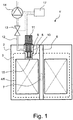
- FIGS. 1 and 2 each show in a schematic vertical sectional view of embodiments of the cryostat arrangement 1 ' according to the invention ; 1 ";1"'; 1 "” with a vacuum container 2 and an object 4 to be cooled (in particular a superconducting magnet coil system 5 in an NMR, MRI or FTMS apparatus), wherein the object 4 to be cooled is arranged inside the vacuum container 2, wherein the vacuum container 2 a Neck tube 8 , which leads to the object to be cooled 4, wherein a cooling arm 10 of a cold head 11 is at least partially disposed in the neck tube 8, wherein around the cooling arm 10 around a closed cavity 9 is formed, which is fluid-tightly sealed against the object to be cooled 4 wherein the cavity 9 is at least partially filled with a cryogenic fluid in normal operation, and wherein a thermal coupling means 15 is provided, suitable for thermal coupling of the cryogenic fluid in the cavity 9 with the object 4 to be cooled.
- a thermal coupling means 15 is provided, suitable for thermal coupling of
- the cryostat arrangement 1 ' according to the invention; 1 “, 1"', 1 “” is characterized in that it comprises a controllable pumping device 14 which the cavity 9 is connected via a controllable valve 13 and with which the cavity 9 can be pumped out in case of a drop in the cooling function of the cold head 11, and that a monitoring device 17 is provided which monitors the cooling function of the cold head 11, and which is designed to in case of waste of the cooling function of the cold head 11, the pump device 14 to activate automatically so that the cavity 9 is pumped out.
- a controllable pumping device 14 which the cavity 9 is connected via a controllable valve 13 and with which the cavity 9 can be pumped out in case of a drop in the cooling function of the cold head 11, and that a monitoring device 17 is provided which monitors the cooling function of the cold head 11, and which is designed to in case of waste of the cooling function of the cold head 11, the pump device 14 to activate automatically so that the cavity 9 is pumped out.
- Fig. 1 schematically shows a first embodiment of a cryostat assembly 1 'according to the invention, comprising a vacuum container 2, in the interior of which a vacuum is arranged.
- a vacuum container 2 in the interior of which a vacuum is arranged.
- a thermal radiation shield 3 dashed lines
- the magnet coil system 5 is here arranged directly in the vacuum of the vacuum container 2.
- the cryostat arrangement 1 ' is provided with a room temperature bore 6, through which a sample volume 7 in the center of the magnet coil system 5 is accessible.
- a sample volume 7 there is a strong, static, approximately homogeneous magnetic field B 0 , which can be used for NMR measurements on a sample in the sample volume 7 with NMR resonators, not shown.
- a neck tube 8 leads to the object 4 to be cooled.
- the neck tube 8 simultaneously forms the enclosure of a cavity 9 immediately surrounding a cooling arm 10 of a cooling head 11 of an active cooling system of the cryostat assembly 1 '.
- the cavity 9 is connected via a pumping line 12 and a valve 13, in particular a shut-off valve, to a pumping device 14, with which the cavity 9 can be evacuated.
- a monitoring device 17 is provided, which also receives (direct or implicit) temperature information from the cooling head 11, and here automatically opens the valve 13 when a limit temperature is exceeded, and the pumping device 14 is activated.
- the cavity 9 is at least partially filled with a cryogenic fluid (not shown in detail in the drawing) which couples the cooling arm 10 to the object 4 to be cooled via a thermal coupling means 15.
- the thermal coupling means 15 is here an upper side of the object 4 to be cooled, which at the same time forms part of the enclosure of the cavity 9.
- the cavity 9 is pumped off with the pumping device 14 and thus the cryogenic fluid in the cavity 9 is cooled.
- Fig. 2 shows a second embodiment of a cryostat assembly according to the invention 1 ", which is largely the first embodiment of Fig. 1 corresponds; therefore only the essential differences are explained.
- the object 4 to be cooled is formed as a cryocontainer 20 within which a superconducting magnet coil system 5 is disposed. Furthermore, in the cryocontainer 20, a second cryogenic fluid, here partially liquid and partially gaseous helium (again not shown in detail in the drawing), arranged.
- the superconducting magnet coil system 5 is typically at least partially immersed in the liquid helium.
- the thermal coupling device 15 is formed here by a part of the upper side of the cryocontainer wall, which limits the cavity 9 at the same time.
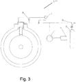
- Fig. 3 shows a third embodiment of the cryostat assembly according to the invention 1 '''in the region of the neck tube 8.
- a pressure sensor 30 with the cavity 9th fluidically connected.
- the pressure sensor can be arranged in particular directly in the cavity 9.
- the output signal of the pressure sensor 30 is fed to the monitoring device 17, which activates the pumping device 14 for pumping out the cavity 9, as soon as the output signal of the pressure sensor 30 exceeds a predetermined first threshold P max , in particular 100 mbar ⁇ P max ⁇ 500 mbar.
- the pump device 14 After being activated due to an exceeding of the first threshold value P max, the pump device 14 pumps the cavity 9 only until the output signal of the pressure sensor 30 falls below a predetermined second threshold value P min , in particular 75 mbar ⁇ P min ⁇ 300 mbar.
- the pumping device 14 comprises a suction pump electrically operated by means of a self-sufficient power source, preferably by means of a battery 31 .
- this embodiment of the cryostat arrangement according to the invention comprises a device for refilling the cavity 9 with the cryogenic fluid.
- This device comprises a reservoir 32 with the cryogenic fluid and a supply line 33 which connects the container 32 with the cavity.
- the supply line 33 is equipped with a pressure reducer 34 .
- the filling process can be carried out in a controlled manner, without causing an overpressure.
- Fig. 4 shows a fourth embodiment of the cryostat assembly according to the invention 1 ''''.
- the pumping device comprises - instead of an electrically operated pump - a cryopump 40, preferably in the Cryostat assembly 1 '''' is integrated.
- the advantage of a cryopump 40 is that it can be made completely passive and therefore very reliable.
- a suitable adsorption material 41 -zB activated carbon is cooled. At a temperature of 4.2K, even helium can be pumped. As in Fig. 4 As shown, the cryopump 40 can be integrated directly into the magnetic cryostat. The pump is operated with a small amount of liquid helium, which is indicated in the drawing below the adsorbent 41. The helium, because it has a temperature of 4.2K, can evaporate into the atmosphere (1000mbar). The cryopump 40 must not be thermally coupled well to the cold head, since when pumping helium with the cryopump 40 heat is released, which would otherwise contribute to the heating of the magnetic coil system 5.
- An essential purpose of the present invention is to provide a cryomagnet which is operated at 4.2K (equivalent to the boiling point of He at normal pressure) to conventional operation, for example at 3K (equivalent to a pressure of about 240mbar).
- This slight lowering of the temperature in the superconductor increases e.g. NbTi the current carrying capacity, so that the design of a much more compact magnet is possible.
- NbTi the current carrying capacity
- the disadvantage here is that the superconductor is more sensitive to a heat input, and it comes at a lower temperature (about 4-5K) already quench. It therefore requires a safety device with which it can be ensured that the temperature of the cryostat can be kept as long as possible at 3K in case of failure of the cooling head.
- FIG. 5 The diagram shown is an example of how the temperature curve of He develops as a function of time when the cooling head fails.
- the MCV cryostat from the cited prior art ( DE 10 2014 218 773 A1 ) serve (line with rhombus symbols). After failure, the temperature rises to the boiling point at atmospheric pressure, where the temperature has a plateau phase, until the liquid portion of the He has passed into the gas phase. Thereafter, the temperature continues to rise until the quench.
- a pressure sensor 30 is necessary, as in Fig. 3 is shown.
- this pressure sensor 30 measures the pressure increase associated therewith in the hollow volume 9 where the cryogen (He) is located and forwards the measured value to the monitoring device 17, which actuates the pump device 14 when a threshold P max is exceeded, which then turns off the hollow volume 9, the cryogen from the gas phase removed up to the desired (sub) pressure.
- a control valve 13 or a variable speed pump is advantageous.
- the battery-buffered pump device 14 switches on and holds the pressure Control, pressure sensor 30 and control valve 13 by pumping helium stable.
- the pressure is slightly above the pressure in normal operation.
- Example normal operation 180mbar.
- Control pressure 300mbar (equivalent to 3.2K).
Landscapes
- Engineering & Computer Science (AREA)
- Physics & Mathematics (AREA)
- General Engineering & Computer Science (AREA)
- Mechanical Engineering (AREA)
- Thermal Sciences (AREA)
- Condensed Matter Physics & Semiconductors (AREA)
- General Physics & Mathematics (AREA)
- Combustion & Propulsion (AREA)
- Chemical & Material Sciences (AREA)
- Electromagnetism (AREA)
- Power Engineering (AREA)
- Containers, Films, And Cooling For Superconductive Devices (AREA)
- Magnetic Resonance Imaging Apparatus (AREA)
Claims (15)
- Arrangement de cryostat (1' ; 1"; 1'''; 1''''), comprenant un réservoir sous vide (2) et un objet (4) à refroidir, l'objet (4) à refroidir étant disposé à l'intérieur du réservoir sous vide (2), le réservoir sous vide (2) comportant un tube formant col (8) qui mène à l'objet (4) à refroidir, un bras de refroidissement (10) d'une tête froide (11) étant disposé au moins partiellement dans le tube formant col (8), un espace creux (9) fermé étant formé autour du bras de refroidissement (10), lequel est rendu étanche aux fluides par rapport à l'objet (4) à refroidir, l'espace creux (9) étant, en fonctionnement normal, au moins partiellement rempli d'un fluide cryogénique, et un moyen de couplage thermique (15) étant présent, adapté pour le couplage thermique du fluide cryogénique dans l'espace creux (9) avec l'objet (4) à refroidir, l'arrangement de cryostat (1' ; 1"; 1'''; 1'''') comportant un système de pompage (14) auquel est raccordé l'espace creux (9) par le biais d'une vanne (13) commandable et avec lequel l'espace creux (9) peut être vidé par pompage dans le cas d'une panne de la fonction de refroidissement de la tête froide (11),
et en ce qu'un dispositif de surveillance (17) est présent, lequel surveille la fonction de refroidissement de la tête froide (11) et lequel est conçu pour activer automatiquement le système de pompage (14) en cas de panne de la fonction de refroidissement de la tête froide (11) de telle sorte que l'espace creux (9) est vidé par pompage,
caractérisé en ce
qu'un capteur de pression (30) est en liaison fluidique avec l'espace creux (9), dont le signal de sortie peut être injecté dans le dispositif de surveillance (17), et en ce que le dispositif de surveillance (17) est réalisé de telle sorte qu'il active le système de pompage (14) en vue de vider l'espace creux (9) par pompage dès que le signal de sortie du capteur de pression (30) dépasse une première valeur de seuil Pmax prédéfinie de 10 kPa (100 mbar) ≤ Pmax ≤ 50 kPa (500 mbar). - Arrangement de cryostat selon la revendication 1, caractérisé en ce que le capteur de pression (30) est disposé dans l'espace creux (9).
- Arrangement de cryostat selon la revendication 2, caractérisé en ce que le système de pompage (14), après son activation en raison d'un dépassement de la première valeur de seuil Pmax ne vide l'espace creux (9) par pompage que jusqu'à ce que le signal de sortie du capteur de pression (30) devienne inférieur à une deuxième valeur de seuil Pmin prédéfinie, avec 7,5 kPa (75 mbar) ≤ Pmin ≤ 30 kPa (300 mbar).
- Arrangement de cryostat selon l'une des revendications précédentes, caractérisé en ce que la vanne (13) commandable est réalisée sous la forme d'une vanne de régulation.
- Arrangement de cryostat selon la revendication 4, caractérisé en ce que le système de pompage (14) est configuré de telle sorte qu'il fonctionne avec une vitesse et/ou une puissance de pompe constante.
- Arrangement de cryostat selon l'une des revendications 1 à 4, caractérisé en ce que le système de pompage (14) est configuré de telle sorte qu'il peut fonctionner avec une vitesse et/ou une puissance de pompe variable réglable.
- Arrangement de cryostat selon la revendication 6, caractérisé en ce que la vanne (13) commandable est réalisée sous la forme d'une vanne tout-ou-rien.
- Arrangement de cryostat selon l'une des revendications 1 à 7, caractérisé en ce que le système de pompage (14) comporte une pompe d'aspiration à fonctionnement électrique, amortie au moyen d'une source de courant autonome.
- Arrangement de cryostat selon l'une des revendications 1 à 7, caractérisé en ce que le système de pompage (14) comporte une cryopompe (40) qui est intégrée dans l'arrangement de cryostat.
- Arrangement de cryostat selon la revendication 9, caractérisé en ce que les surfaces froides de pompage de la cryopompe (40) sont couplées thermiquement à l'objet (4) à refroidir, une conduite de liaison de l'espace creux (9) aux surfaces froides de pompage s'étendant entièrement dans le réservoir sous vide (2).
- Arrangement de cryostat selon l'une des revendications précédentes, caractérisé en ce qu'une conduite d'arrivée (33) est reliée fluidiquement à l'espace creux (9), avec laquelle l'espace creux (9) peut de nouveau être rempli de fluide cryogénique après la remise en service de la fonction de refroidissement l'espace creux (9).
- Procédé pour faire fonctionner un arrangement de cryostat (1'; 1"; 1'''; 1'''') selon l'une des revendications précédentes, comprenant un réservoir sous vide (2) et un objet (4) à refroidir, l'objet (4) à refroidir étant disposé à l'intérieur du réservoir sous vide (2), le réservoir sous vide (2) comportant un tube formant col (8) qui mène à l'objet (4) à refroidir, un bras de refroidissement (10) d'une tête froide (11) étant disposé au moins partiellement dans le tube formant col (8), un espace creux (9) fermé étant formé autour du bras de refroidissement (10), lequel est rendu étanche aux fluides par rapport à l'objet (4) à refroidir, l'espace creux (9) étant, en fonctionnement normal, au moins partiellement rempli d'un fluide cryogénique, et un moyen de couplage thermique (15) étant présent, adapté pour le couplage thermique du fluide cryogénique dans l'espace creux (9) avec l'objet (4) à refroidir,
caractérisé en ce
que l'espace creux (9) est vidé par pompage par le biais d'un système de pompage (14) de telle sorte que la pression dans l'espace creux (9) ne dépasse pas une première valeur de seuil Pmax prédéfinie de 10 kPa (100 mbar) ≤ Pmax ≤ 50 kPa (500 mbar). - Procédé selon la revendication 12, caractérisé en ce que l'espace creux (9) est vidé par pompage par le biais d'un système de pompage (14) de telle sorte que la pression dans l'espace creux (9) ne devient pas inférieure à une deuxième valeur de seuil prédéfinie Pmin < Pmax.
- Procédé selon l'une des revendications 12 ou 13, caractérisé en ce que le fluide cryogénique utilisé est de l'hélium et en ce que le système de pompage (14) fonctionne de telle sorte qu'en fonctionnement normal, la pression dans l'espace creux (9) est comprise entre 15 kPa (150 mbar) et 35 kPa (350 mbar).
- Procédé selon l'une des revendications 12 à 14 pour faire fonctionner l'arrangement de cryostat (1' ; 1" ; 1''' ; 1'''') comprenant le système de pompage (14) commandable, auquel l'espace creux (9) est raccordé par le biais de la vanne (13) commandable, et comprenant aussi le dispositif de surveillance (17) qui surveille la fonction de refroidissement de la tête froide (11) et/ou la pression dans l'espace creux (9), caractérisé en ce que le dispositif de surveillance (17), en cas de panne de la fonction de refroidissement de la tête froide (11) et/ou en cas de dépassement de la pression dans l'espace creux (9) au-dessus de la première valeur de seuil Pmax prédéfinie, active le système de pompage (14) de telle sorte que l'espace creux (9) est vidé par pompage à une pression inférieure à la valeur de seuil Pmax.
Applications Claiming Priority (2)
| Application Number | Priority Date | Filing Date | Title |
|---|---|---|---|
| DE102016218000.2A DE102016218000B3 (de) | 2016-09-20 | 2016-09-20 | Kryostatenanordnung mit einem Vakuumbehälter und einem zu kühlenden Objekt, mit evakuierbarem Hohlraum |
| PCT/EP2017/071340 WO2018054648A1 (fr) | 2016-09-20 | 2017-08-24 | Dispositif et procédé permettant un fonctionnement surrefroidi d'un cryostat avec de faibles quantités de réfrigérant |
Publications (2)
| Publication Number | Publication Date |
|---|---|
| EP3488451A1 EP3488451A1 (fr) | 2019-05-29 |
| EP3488451B1 true EP3488451B1 (fr) | 2019-12-04 |
Family
ID=59702726
Family Applications (2)
| Application Number | Title | Priority Date | Filing Date |
|---|---|---|---|
| EP17757758.2A Active EP3488451B1 (fr) | 2016-09-20 | 2017-08-24 | Dispositif et procédé permettant un fonctionnement surrefroidi d'un cryostat avec de faibles quantités de réfrigérant |
| EP17191011.0A Active EP3296669B1 (fr) | 2016-09-20 | 2017-09-14 | Ensemble cryostat doté d'un réservoir à vide et d'un objet à refroidir et doté d'un espace creux pouvant être vidé |
Family Applications After (1)
| Application Number | Title | Priority Date | Filing Date |
|---|---|---|---|
| EP17191011.0A Active EP3296669B1 (fr) | 2016-09-20 | 2017-09-14 | Ensemble cryostat doté d'un réservoir à vide et d'un objet à refroidir et doté d'un espace creux pouvant être vidé |
Country Status (6)
| Country | Link |
|---|---|
| US (2) | US10101420B2 (fr) |
| EP (2) | EP3488451B1 (fr) |
| JP (1) | JP6338755B2 (fr) |
| CN (2) | CN109716457B (fr) |
| DE (1) | DE102016218000B3 (fr) |
| WO (1) | WO2018054648A1 (fr) |
Families Citing this family (27)
| Publication number | Priority date | Publication date | Assignee | Title |
|---|---|---|---|---|
| DE102016208226A1 (de) * | 2016-05-12 | 2017-11-16 | Bruker Biospin Ag | Kryogenfreies Magnetsystem mit magnetokalorischer Wärmesenke |
| DE102016112851A1 (de) * | 2016-07-13 | 2018-01-18 | Viessmann Werke Gmbh & Co Kg | Kältemodul |
| WO2018075770A1 (fr) * | 2016-10-19 | 2018-04-26 | Chart Inc. | Dispositif, système et procédé de bras de dosage interchangeable |
| PL3495711T3 (pl) * | 2017-12-08 | 2021-01-11 | Linde Gmbh | Zbiornik transportowy ze schładzaną osłoną termiczną |
| CN111656082A (zh) * | 2018-01-12 | 2020-09-11 | 亚致力气体科技有限公司 | 用于低温储存和运输挥发性气体的热级联 |
| US11035807B2 (en) * | 2018-03-07 | 2021-06-15 | General Electric Company | Thermal interposer for a cryogenic cooling system |
| CN108387064B (zh) * | 2018-04-03 | 2024-06-14 | 同方威视技术股份有限公司 | 低温恒温器 |
| JP2021522462A (ja) | 2018-04-19 | 2021-08-30 | エンバー テクノロジーズ, インコーポレイテッド | アクティブ温度制御を備えた携帯型冷却器 |
| US10989466B2 (en) | 2019-01-11 | 2021-04-27 | Ember Technologies, Inc. | Portable cooler with active temperature control |
| JP7195980B2 (ja) * | 2019-03-08 | 2022-12-26 | 住友重機械工業株式会社 | 超伝導磁石装置、サイクロトロン、および超伝導磁石装置の再起動方法 |
| EP4621318A3 (fr) | 2019-06-25 | 2025-11-26 | YETI Coolers, LLC | Refroidisseur portable |
| US11162716B2 (en) | 2019-06-25 | 2021-11-02 | Ember Technologies, Inc. | Portable cooler |
| US11668508B2 (en) | 2019-06-25 | 2023-06-06 | Ember Technologies, Inc. | Portable cooler |
| DE102020201522A1 (de) * | 2020-02-07 | 2021-08-12 | Bruker Switzerland Ag | NMR-Messanordnung mit kalter Bohrung des Kryostaten |
| CA3178289A1 (fr) | 2020-04-03 | 2021-10-07 | Clayton Alexander | Refroidisseur portable a regulation de temperature active |
| CN112038035B (zh) * | 2020-09-18 | 2022-03-25 | 中国科学院合肥物质科学研究院 | 一种基于层间叠片整体热传导的密绕型超导磁体制冷装置 |
| CN115266801B (zh) * | 2021-04-29 | 2025-12-19 | 中国航天科工飞航技术研究院(中国航天海鹰机电技术研究院) | 一种适用于多种温区的可拆卸液位式热负载测试系统 |
| CN113130165B (zh) * | 2021-06-17 | 2022-03-25 | 西南交通大学 | 一种磁悬浮列车用超导块材冷却装置及冷却方法 |
| DE102021206392A1 (de) | 2021-06-22 | 2022-12-22 | Bruker Biospin Gmbh | Autonomes Herunterkühlen eines supraleitfähigen, trocken-gekühlten MR-Magnetspulensystems |
| CN114791177B (zh) * | 2022-01-24 | 2023-07-21 | 深圳市鸿森精科实业有限公司 | Mri用低温制冷机 |
| CN114879106A (zh) * | 2022-04-24 | 2022-08-09 | 鑫高益医疗设备股份有限公司 | 一种无液氦核磁共振仪预冷系统及预冷方法 |
| DE102022204476A1 (de) | 2022-05-06 | 2023-11-09 | Bruker Biospin Gmbh | Autonome Strombeladung eines supraleitfähigen, trocken-gekühlten MR-Magnetspulensystems |
| CN115064335B (zh) * | 2022-08-16 | 2022-10-25 | 西门子数字医疗科技(上海)有限公司 | 超导磁体的再冷却方法、装置以及磁共振成像系统 |
| US12566023B2 (en) * | 2022-12-14 | 2026-03-03 | International Business Machines Corporation | Modular cooling farm for cryogenic application |
| GB202302817D0 (en) * | 2023-02-27 | 2023-04-12 | Cryogenic Ltd | Cryogen-free solid state MAS NMR system with liquid state NMR potential |
| EP4668295A1 (fr) * | 2024-06-18 | 2025-12-24 | Siemens Healthineers AG | Dispositif de refroidissement pour refroidir un aimant supraconducteur |
| FI131647B1 (en) * | 2024-06-28 | 2025-08-21 | Bluefors Oy | CRYOGENIC COOLING SYSTEM |
Family Cites Families (21)
| Publication number | Priority date | Publication date | Assignee | Title |
|---|---|---|---|---|
| JPS62185383A (ja) | 1986-02-12 | 1987-08-13 | Toshiba Corp | 極低温容器 |
| JPS63207958A (ja) * | 1987-02-23 | 1988-08-29 | Toshiba Corp | 冷凍機 |
| JPS6423062A (en) * | 1987-07-16 | 1989-01-25 | Toshiba Corp | Cryogenic refrigerating machine |
| JPH05243042A (ja) * | 1992-02-26 | 1993-09-21 | Hitachi Cable Ltd | 超電導コイル冷却装置 |
| JP2005055003A (ja) * | 2003-08-01 | 2005-03-03 | Sumitomo Heavy Ind Ltd | 冷凍機装着構造、冷凍機冷却型超電導マグネット装置、冷凍機装着構造を備えた凝縮装置、及び冷凍機の装着方法 |
| JP4494027B2 (ja) * | 2004-01-26 | 2010-06-30 | 株式会社神戸製鋼所 | 極低温装置 |
| US7318318B2 (en) | 2004-03-13 | 2008-01-15 | Bruker Biospin Gmbh | Superconducting magnet system with refrigerator |
| DE102004012416B4 (de) * | 2004-03-13 | 2006-04-20 | Bruker Biospin Gmbh | Supraleitendes Magnetsystem mit Pulsrohr-Kühler |
| GB0411607D0 (en) * | 2004-05-25 | 2004-06-30 | Oxford Magnet Tech | Recondenser interface |
| GB0411605D0 (en) * | 2004-05-25 | 2004-06-30 | Oxford Magnet Tech | Reduction of croygen loss during transportation |
| DE102004034729B4 (de) * | 2004-07-17 | 2006-12-07 | Bruker Biospin Ag | Kryostatanordnung mit Kryokühler und Gasspaltwärmeübertrager |
| EP1736732A1 (fr) * | 2005-06-20 | 2006-12-27 | Leica Geosystems AG | Procédé de nivellement d'un appareil de mesure et un appareil de mesure comprenant un dispositif de nivellement |
| DE102005029151B4 (de) * | 2005-06-23 | 2008-08-07 | Bruker Biospin Ag | Kryostatanordnung mit Kryokühler |
| DE102005035894B3 (de) * | 2005-07-30 | 2007-04-05 | Bruker Biospin Gmbh | Supraleitendes Magnetsystem mit Strahlungsschild zwischen Kryofluidtank und Refrigerator |
| DE102005042834B4 (de) * | 2005-09-09 | 2013-04-11 | Bruker Biospin Gmbh | Supraleitendes Magnetsystem mit Refrigerator zur Rückverflüssigung von Kryofluid in einer Rohrleitung |
| GB0721572D0 (en) * | 2007-11-02 | 2007-12-12 | Siemens Magnet Technology Ltd | Cryostat for reduced cryogen consumption |
| GB2457054B (en) * | 2008-01-31 | 2010-01-06 | Siemens Magnet Technology Ltd | A method and apparatus for controlling the cooling power of a cryogenic refigerator delivered to a cryogen vessel |
| US8729894B2 (en) | 2010-07-30 | 2014-05-20 | General Electric Company | System and method for operating a magnetic resonance imaging system during ramping |
| GB2545139B (en) * | 2014-04-16 | 2018-05-30 | Siemens Healthcare Ltd | Thermally disconnecting a cryogenic vessel from a refrigerator |
| DE102014218773B4 (de) * | 2014-09-18 | 2020-11-26 | Bruker Biospin Gmbh | Automatische thermische Entkopplung eines Kühlkopfs |
| DE102014219849B3 (de) * | 2014-09-30 | 2015-12-10 | Bruker Biospin Gmbh | Kühlvorrichtung mit Kryostat und Kaltkopf mit verringerter mechanischer Kopplung |
-
2016
- 2016-09-20 DE DE102016218000.2A patent/DE102016218000B3/de active Active
-
2017
- 2017-08-24 CN CN201780057869.1A patent/CN109716457B/zh active Active
- 2017-08-24 WO PCT/EP2017/071340 patent/WO2018054648A1/fr not_active Ceased
- 2017-08-24 EP EP17757758.2A patent/EP3488451B1/fr active Active
- 2017-09-12 JP JP2017174965A patent/JP6338755B2/ja active Active
- 2017-09-14 EP EP17191011.0A patent/EP3296669B1/fr active Active
- 2017-09-20 US US15/710,283 patent/US10101420B2/en active Active
- 2017-09-20 CN CN201710848722.6A patent/CN107845475B/zh active Active
-
2019
- 2019-03-20 US US16/359,121 patent/US20190212049A1/en not_active Abandoned
Non-Patent Citations (1)
| Title |
|---|
| None * |
Also Published As
| Publication number | Publication date |
|---|---|
| CN107845475A (zh) | 2018-03-27 |
| US20190212049A1 (en) | 2019-07-11 |
| WO2018054648A1 (fr) | 2018-03-29 |
| JP2018071962A (ja) | 2018-05-10 |
| EP3296669A1 (fr) | 2018-03-21 |
| DE102016218000B3 (de) | 2017-10-05 |
| JP6338755B2 (ja) | 2018-06-06 |
| EP3296669B1 (fr) | 2019-02-13 |
| US10101420B2 (en) | 2018-10-16 |
| CN109716457A (zh) | 2019-05-03 |
| CN109716457B (zh) | 2020-11-20 |
| US20180081011A1 (en) | 2018-03-22 |
| EP3488451A1 (fr) | 2019-05-29 |
| CN107845475B (zh) | 2019-11-12 |
Similar Documents
| Publication | Publication Date | Title |
|---|---|---|
| EP3488451B1 (fr) | Dispositif et procédé permettant un fonctionnement surrefroidi d'un cryostat avec de faibles quantités de réfrigérant | |
| EP3285032B1 (fr) | Agencement de cryostat et son procédé de fonctionnement | |
| DE102013011212B4 (de) | Vorrichtung zum Kühlen eines Verbrauchers mit einer unterkühlten Flüssigkeit in einem Kühlkreislauf | |
| DE102011078608B4 (de) | Kryostatanordnung | |
| EP1736723B1 (fr) | Dispositif de cryostat avec cryorefroidisseur | |
| EP1628109B1 (fr) | Dispositif de cryostat | |
| EP2821741B1 (fr) | Procédé de rééquipement d'un ensemble cryostat pour refroidissement par circulation | |
| DE102022209941A1 (de) | Vorrichtung zum Transfer von flüssigem Helium, mit verringerten Transfer-Verlusten | |
| DE69933982T2 (de) | Supraleitender Kryostat-Magnet mit Kältemittel-Durchhalte-Reserve | |
| DE102010028750B4 (de) | Verlustarme Kryostatenanordnung | |
| DE102010038713B4 (de) | Hochfeld-NMR-Apparatur mit Überschuss-Kühlleistung und integrierter Helium-Rückverflüssigung | |
| EP1574777B1 (fr) | Cryostat pour un système magnétique supraconducteur | |
| EP4575352A1 (fr) | Dispositif et procédé de transfert d'hélium liquide dans un cryostat d'application | |
| EP4109121B1 (fr) | Refroidissement autonome d'un système supraconducteur de bobine magnétique rm à refroidissement à sec | |
| EP1742234B1 (fr) | Ensemble de cryostat horizontal en surfusion | |
| EP4479762B1 (fr) | Charge de courant autonome d'un système de bobine d'électro-aimant rm supraconducteur refroidi à sec | |
| DE102012201108A1 (de) | Vorrichtung zur Kühlung einer supraleitenden Maschine | |
| EP4652469B1 (fr) | Dispositif de régulation de la pression dans un réservoir d'hélium d'un aimant rmn, comprenant deux capteurs de pression | |
| DE102024206736B3 (de) | Vorratskryostat für flüssiges Helium, mit vertikal ausgedehntem Konvektionshemmsystem | |
| DE202005010892U1 (de) | Unterkühlte Horizontalkryostatanordnung | |
| DE1092937B (de) | Verfahren fuer den Betrieb einer Kuehlanlage und Kuehlanlage zur Durchfuehrung des Verfahrens |
Legal Events
| Date | Code | Title | Description |
|---|---|---|---|
| STAA | Information on the status of an ep patent application or granted ep patent |
Free format text: STATUS: UNKNOWN |
|
| STAA | Information on the status of an ep patent application or granted ep patent |
Free format text: STATUS: THE INTERNATIONAL PUBLICATION HAS BEEN MADE |
|
| PUAI | Public reference made under article 153(3) epc to a published international application that has entered the european phase |
Free format text: ORIGINAL CODE: 0009012 |
|
| STAA | Information on the status of an ep patent application or granted ep patent |
Free format text: STATUS: REQUEST FOR EXAMINATION WAS MADE |
|
| 17P | Request for examination filed |
Effective date: 20190220 |
|
| AK | Designated contracting states |
Kind code of ref document: A1 Designated state(s): AL AT BE BG CH CY CZ DE DK EE ES FI FR GB GR HR HU IE IS IT LI LT LU LV MC MK MT NL NO PL PT RO RS SE SI SK SM TR |
|
| AX | Request for extension of the european patent |
Extension state: BA ME |
|
| GRAP | Despatch of communication of intention to grant a patent |
Free format text: ORIGINAL CODE: EPIDOSNIGR1 |
|
| STAA | Information on the status of an ep patent application or granted ep patent |
Free format text: STATUS: GRANT OF PATENT IS INTENDED |
|
| DAV | Request for validation of the european patent (deleted) | ||
| DAX | Request for extension of the european patent (deleted) | ||
| INTG | Intention to grant announced |
Effective date: 20190703 |
|
| GRAS | Grant fee paid |
Free format text: ORIGINAL CODE: EPIDOSNIGR3 |
|
| GRAA | (expected) grant |
Free format text: ORIGINAL CODE: 0009210 |
|
| STAA | Information on the status of an ep patent application or granted ep patent |
Free format text: STATUS: THE PATENT HAS BEEN GRANTED |
|
| AK | Designated contracting states |
Kind code of ref document: B1 Designated state(s): AL AT BE BG CH CY CZ DE DK EE ES FI FR GB GR HR HU IE IS IT LI LT LU LV MC MK MT NL NO PL PT RO RS SE SI SK SM TR |
|
| REG | Reference to a national code |
Ref country code: GB Ref legal event code: FG4D Free format text: NOT ENGLISH |
|
| REG | Reference to a national code |
Ref country code: CH Ref legal event code: EP |
|
| REG | Reference to a national code |
Ref country code: AT Ref legal event code: REF Ref document number: 1210420 Country of ref document: AT Kind code of ref document: T Effective date: 20191215 |
|
| REG | Reference to a national code |
Ref country code: DE Ref legal event code: R096 Ref document number: 502017003069 Country of ref document: DE |
|
| REG | Reference to a national code |
Ref country code: IE Ref legal event code: FG4D Free format text: LANGUAGE OF EP DOCUMENT: GERMAN |
|
| REG | Reference to a national code |
Ref country code: NL Ref legal event code: MP Effective date: 20191204 |
|
| REG | Reference to a national code |
Ref country code: LT Ref legal event code: MG4D |
|
| PG25 | Lapsed in a contracting state [announced via postgrant information from national office to epo] |
Ref country code: LV Free format text: LAPSE BECAUSE OF FAILURE TO SUBMIT A TRANSLATION OF THE DESCRIPTION OR TO PAY THE FEE WITHIN THE PRESCRIBED TIME-LIMIT Effective date: 20191204 Ref country code: SE Free format text: LAPSE BECAUSE OF FAILURE TO SUBMIT A TRANSLATION OF THE DESCRIPTION OR TO PAY THE FEE WITHIN THE PRESCRIBED TIME-LIMIT Effective date: 20191204 Ref country code: NO Free format text: LAPSE BECAUSE OF FAILURE TO SUBMIT A TRANSLATION OF THE DESCRIPTION OR TO PAY THE FEE WITHIN THE PRESCRIBED TIME-LIMIT Effective date: 20200304 Ref country code: GR Free format text: LAPSE BECAUSE OF FAILURE TO SUBMIT A TRANSLATION OF THE DESCRIPTION OR TO PAY THE FEE WITHIN THE PRESCRIBED TIME-LIMIT Effective date: 20200305 Ref country code: FI Free format text: LAPSE BECAUSE OF FAILURE TO SUBMIT A TRANSLATION OF THE DESCRIPTION OR TO PAY THE FEE WITHIN THE PRESCRIBED TIME-LIMIT Effective date: 20191204 Ref country code: LT Free format text: LAPSE BECAUSE OF FAILURE TO SUBMIT A TRANSLATION OF THE DESCRIPTION OR TO PAY THE FEE WITHIN THE PRESCRIBED TIME-LIMIT Effective date: 20191204 Ref country code: BG Free format text: LAPSE BECAUSE OF FAILURE TO SUBMIT A TRANSLATION OF THE DESCRIPTION OR TO PAY THE FEE WITHIN THE PRESCRIBED TIME-LIMIT Effective date: 20200304 |
|
| PG25 | Lapsed in a contracting state [announced via postgrant information from national office to epo] |
Ref country code: RS Free format text: LAPSE BECAUSE OF FAILURE TO SUBMIT A TRANSLATION OF THE DESCRIPTION OR TO PAY THE FEE WITHIN THE PRESCRIBED TIME-LIMIT Effective date: 20191204 Ref country code: HR Free format text: LAPSE BECAUSE OF FAILURE TO SUBMIT A TRANSLATION OF THE DESCRIPTION OR TO PAY THE FEE WITHIN THE PRESCRIBED TIME-LIMIT Effective date: 20191204 |
|
| PG25 | Lapsed in a contracting state [announced via postgrant information from national office to epo] |
Ref country code: AL Free format text: LAPSE BECAUSE OF FAILURE TO SUBMIT A TRANSLATION OF THE DESCRIPTION OR TO PAY THE FEE WITHIN THE PRESCRIBED TIME-LIMIT Effective date: 20191204 |
|
| PG25 | Lapsed in a contracting state [announced via postgrant information from national office to epo] |
Ref country code: RO Free format text: LAPSE BECAUSE OF FAILURE TO SUBMIT A TRANSLATION OF THE DESCRIPTION OR TO PAY THE FEE WITHIN THE PRESCRIBED TIME-LIMIT Effective date: 20191204 Ref country code: EE Free format text: LAPSE BECAUSE OF FAILURE TO SUBMIT A TRANSLATION OF THE DESCRIPTION OR TO PAY THE FEE WITHIN THE PRESCRIBED TIME-LIMIT Effective date: 20191204 Ref country code: PT Free format text: LAPSE BECAUSE OF FAILURE TO SUBMIT A TRANSLATION OF THE DESCRIPTION OR TO PAY THE FEE WITHIN THE PRESCRIBED TIME-LIMIT Effective date: 20200429 Ref country code: ES Free format text: LAPSE BECAUSE OF FAILURE TO SUBMIT A TRANSLATION OF THE DESCRIPTION OR TO PAY THE FEE WITHIN THE PRESCRIBED TIME-LIMIT Effective date: 20191204 Ref country code: CZ Free format text: LAPSE BECAUSE OF FAILURE TO SUBMIT A TRANSLATION OF THE DESCRIPTION OR TO PAY THE FEE WITHIN THE PRESCRIBED TIME-LIMIT Effective date: 20191204 Ref country code: NL Free format text: LAPSE BECAUSE OF FAILURE TO SUBMIT A TRANSLATION OF THE DESCRIPTION OR TO PAY THE FEE WITHIN THE PRESCRIBED TIME-LIMIT Effective date: 20191204 |
|
| PG25 | Lapsed in a contracting state [announced via postgrant information from national office to epo] |
Ref country code: SM Free format text: LAPSE BECAUSE OF FAILURE TO SUBMIT A TRANSLATION OF THE DESCRIPTION OR TO PAY THE FEE WITHIN THE PRESCRIBED TIME-LIMIT Effective date: 20191204 Ref country code: SK Free format text: LAPSE BECAUSE OF FAILURE TO SUBMIT A TRANSLATION OF THE DESCRIPTION OR TO PAY THE FEE WITHIN THE PRESCRIBED TIME-LIMIT Effective date: 20191204 Ref country code: IS Free format text: LAPSE BECAUSE OF FAILURE TO SUBMIT A TRANSLATION OF THE DESCRIPTION OR TO PAY THE FEE WITHIN THE PRESCRIBED TIME-LIMIT Effective date: 20200404 |
|
| REG | Reference to a national code |
Ref country code: DE Ref legal event code: R097 Ref document number: 502017003069 Country of ref document: DE |
|
| PLBE | No opposition filed within time limit |
Free format text: ORIGINAL CODE: 0009261 |
|
| STAA | Information on the status of an ep patent application or granted ep patent |
Free format text: STATUS: NO OPPOSITION FILED WITHIN TIME LIMIT |
|
| PG25 | Lapsed in a contracting state [announced via postgrant information from national office to epo] |
Ref country code: DK Free format text: LAPSE BECAUSE OF FAILURE TO SUBMIT A TRANSLATION OF THE DESCRIPTION OR TO PAY THE FEE WITHIN THE PRESCRIBED TIME-LIMIT Effective date: 20191204 |
|
| 26N | No opposition filed |
Effective date: 20200907 |
|
| PG25 | Lapsed in a contracting state [announced via postgrant information from national office to epo] |
Ref country code: PL Free format text: LAPSE BECAUSE OF FAILURE TO SUBMIT A TRANSLATION OF THE DESCRIPTION OR TO PAY THE FEE WITHIN THE PRESCRIBED TIME-LIMIT Effective date: 20191204 |
|
| PG25 | Lapsed in a contracting state [announced via postgrant information from national office to epo] |
Ref country code: IT Free format text: LAPSE BECAUSE OF FAILURE TO SUBMIT A TRANSLATION OF THE DESCRIPTION OR TO PAY THE FEE WITHIN THE PRESCRIBED TIME-LIMIT Effective date: 20191204 |
|
| PG25 | Lapsed in a contracting state [announced via postgrant information from national office to epo] |
Ref country code: MC Free format text: LAPSE BECAUSE OF FAILURE TO SUBMIT A TRANSLATION OF THE DESCRIPTION OR TO PAY THE FEE WITHIN THE PRESCRIBED TIME-LIMIT Effective date: 20191204 |
|
| PG25 | Lapsed in a contracting state [announced via postgrant information from national office to epo] |
Ref country code: LU Free format text: LAPSE BECAUSE OF NON-PAYMENT OF DUE FEES Effective date: 20200824 |
|
| REG | Reference to a national code |
Ref country code: BE Ref legal event code: MM Effective date: 20200831 |
|
| PG25 | Lapsed in a contracting state [announced via postgrant information from national office to epo] |
Ref country code: IE Free format text: LAPSE BECAUSE OF NON-PAYMENT OF DUE FEES Effective date: 20200824 Ref country code: BE Free format text: LAPSE BECAUSE OF NON-PAYMENT OF DUE FEES Effective date: 20200831 |
|
| PG25 | Lapsed in a contracting state [announced via postgrant information from national office to epo] |
Ref country code: TR Free format text: LAPSE BECAUSE OF FAILURE TO SUBMIT A TRANSLATION OF THE DESCRIPTION OR TO PAY THE FEE WITHIN THE PRESCRIBED TIME-LIMIT Effective date: 20191204 Ref country code: MT Free format text: LAPSE BECAUSE OF FAILURE TO SUBMIT A TRANSLATION OF THE DESCRIPTION OR TO PAY THE FEE WITHIN THE PRESCRIBED TIME-LIMIT Effective date: 20191204 Ref country code: CY Free format text: LAPSE BECAUSE OF FAILURE TO SUBMIT A TRANSLATION OF THE DESCRIPTION OR TO PAY THE FEE WITHIN THE PRESCRIBED TIME-LIMIT Effective date: 20191204 |
|
| PG25 | Lapsed in a contracting state [announced via postgrant information from national office to epo] |
Ref country code: MK Free format text: LAPSE BECAUSE OF FAILURE TO SUBMIT A TRANSLATION OF THE DESCRIPTION OR TO PAY THE FEE WITHIN THE PRESCRIBED TIME-LIMIT Effective date: 20191204 |
|
| PG25 | Lapsed in a contracting state [announced via postgrant information from national office to epo] |
Ref country code: SI Free format text: LAPSE BECAUSE OF FAILURE TO SUBMIT A TRANSLATION OF THE DESCRIPTION OR TO PAY THE FEE WITHIN THE PRESCRIBED TIME-LIMIT Effective date: 20191204 |
|
| REG | Reference to a national code |
Ref country code: AT Ref legal event code: MM01 Ref document number: 1210420 Country of ref document: AT Kind code of ref document: T Effective date: 20220824 |
|
| PG25 | Lapsed in a contracting state [announced via postgrant information from national office to epo] |
Ref country code: AT Free format text: LAPSE BECAUSE OF NON-PAYMENT OF DUE FEES Effective date: 20220824 |
|
| P01 | Opt-out of the competence of the unified patent court (upc) registered |
Effective date: 20231030 |
|
| REG | Reference to a national code |
Ref country code: GB Ref legal event code: 732E Free format text: REGISTERED BETWEEN 20240829 AND 20240904 |
|
| REG | Reference to a national code |
Ref country code: DE Ref legal event code: R081 Ref document number: 502017003069 Country of ref document: DE Owner name: BRUKER BIOSPIN GMBH & CO. KG, DE Free format text: FORMER OWNER: BRUKER BIOSPIN GMBH, 76287 RHEINSTETTEN, DE |
|
| PGFP | Annual fee paid to national office [announced via postgrant information from national office to epo] |
Ref country code: DE Payment date: 20250819 Year of fee payment: 9 |
|
| PGFP | Annual fee paid to national office [announced via postgrant information from national office to epo] |
Ref country code: GB Payment date: 20250818 Year of fee payment: 9 |
|
| PGFP | Annual fee paid to national office [announced via postgrant information from national office to epo] |
Ref country code: FR Payment date: 20250821 Year of fee payment: 9 |
|
| PGFP | Annual fee paid to national office [announced via postgrant information from national office to epo] |
Ref country code: CH Payment date: 20250901 Year of fee payment: 9 |