EP4480366A1 - Support de toilettes - Google Patents
Support de toilettes Download PDFInfo
- Publication number
- EP4480366A1 EP4480366A1 EP23180635.7A EP23180635A EP4480366A1 EP 4480366 A1 EP4480366 A1 EP 4480366A1 EP 23180635 A EP23180635 A EP 23180635A EP 4480366 A1 EP4480366 A1 EP 4480366A1
- Authority
- EP
- European Patent Office
- Prior art keywords
- bearing
- edge
- alignment
- toilet
- section
- Prior art date
- Legal status (The legal status is an assumption and is not a legal conclusion. Google has not performed a legal analysis and makes no representation as to the accuracy of the status listed.)
- Pending
Links
Images


Classifications
-
- A—HUMAN NECESSITIES
- A47—FURNITURE; DOMESTIC ARTICLES OR APPLIANCES; COFFEE MILLS; SPICE MILLS; SUCTION CLEANERS IN GENERAL
- A47K—SANITARY EQUIPMENT; ACCESSORIES THEREFOR, e.g. TOILET ACCESSORIES
- A47K13/00—Seats or covers for all kinds of closets
- A47K13/12—Hinges
-
- A—HUMAN NECESSITIES
- A47—FURNITURE; DOMESTIC ARTICLES OR APPLIANCES; COFFEE MILLS; SPICE MILLS; SUCTION CLEANERS IN GENERAL
- A47K—SANITARY EQUIPMENT; ACCESSORIES THEREFOR, e.g. TOILET ACCESSORIES
- A47K13/00—Seats or covers for all kinds of closets
- A47K13/24—Parts or details not covered in, or of interest apart from, groups A47K13/02 - A47K13/22
- A47K13/26—Mounting devices for seats or covers
Definitions
- the present invention relates to a toilet seat cover according to claim 1.
- Toilet seats are known in the art and typically comprise a hinge and at least one toilet seat element, such as a toilet seat ring or a toilet lid.
- a toilet cover is typically pivoted on hinges, which in turn are mounted on the toilet body. Swivel dampers arranged on the hinges allow the pivoting of the toilet cover to be dampened.
- Such hinges are typically complex in design and are correspondingly difficult to install.
- the invention is based on the object of providing a toilet seat arrangement which can be easily assembled or manufactured.
- a toilet support comprises at least one toilet support element and at least one hinge element, with which the at least one toilet support element can be pivotally connected to a sanitary article, such as a toilet bowl.
- a sanitary article such as a toilet bowl.
- the hinge element has a hinge receptacle and a hinge pin with a bearing section and a pivot section, which is pivotally mounted in the hinge receptacle.
- the at least one toilet support element has at least one bearing opening, into which the Bearing section protrudes. Typically, one bearing opening is arranged per hinge element.
- the bearing section and the bearing opening each have a bearing surface with at least one surface section, which surface section requires an alignment of the hinge pin with respect to a rotation about its central axis relative to the bearing opening.
- the bearing section has at least one alignment edge in the area of its front end, which is designed in such a way that when the bearing section is pushed into the bearing opening, the hinge pin pivots about its central axis, so that the surface section of the bearing section can be aligned relative to the surface section of the bearing opening.
- the arrangement of the alignment edge has the advantage that the hinge pin is automatically aligned during assembly, during which the hinge pin is moved into the bearing opening along the central axis.
- the alignment edge is designed in particular in such a way that the hinge pin pivots automatically and in particular continuously as it moves into the bearing opening. As a result of the movement and the application of force in the direction of the central axis, the hinge pin rotates and aligns itself accordingly.
- the bearing surfaces or surface sections are designed in such a way that a rotationally fixed connection is created between the bearing opening and the bearing section when the hinge pin protrudes into the bearing opening. This means that when the toilet support element is pivoted, the hinge pin is pivoted along with it.
- the surface section is a flat surface section which is defined by a plane running at a distance from the central axis.
- the surface section is a non-circular or non-cylindrical surface section running around the central axis.
- the alignment edge extends from a front edge to a rear edge, wherein the rear edge is set back with respect to the front edge in the direction of insertion of the hinge pin into the bearing opening.
- the front edge and/or the rear edge extend at right angles to the central axis, wherein the front edge and/or the rear edge do not intersect the central axis.
- the two edges run parallel to each other, wherein the both edges lie on different sides with respect to the central axis.
- leading edge is located closer to the front end of the hinge pin than the trailing edge.
- the front edge can also serve for alignment and guide the rotational movement of the bearing pin until the alignment edge comes into contact with an edge of the bearing opening.
- the alignment edge is arranged on one end face of the bearing section.
- the alignment edge runs with a slope on a circular cylinder that extends around the central axis.
- the alignment edge runs as a section of a helical line that extends a circular segment around the central axis.
- the alignment edge preferably extends around the circular cylinder at an angle of a maximum of 90°, in particular in the range of 70° to 90°.
- the slope of the alignment edge is preferably constant in the direction of the central axis.
- the hinge pin further has an inner edge which runs with a slope on a circular cylinder extending around the central axis.
- the inner edge preferably extends at an angle of maximum 90° around the circular cylinder.
- the slope of the inner edge is preferably constant in the direction of the central axis.
- the alignment edge extends at a smaller angle around the circular cylinder than the inner edge.
- the circular cylinder on which the alignment edge runs preferably has a larger diameter than the circular cylinder on which the inner edge runs.
- the slope of the inner edge is equal to the slope of the alignment edge.
- the slope of the inner edge is smaller or larger than the slope of the alignment edge.
- the hinge pin preferably has a tenon extension which extends from the at least one alignment edge at the front in the direction of the central axis.
- the tenon extension preferably has a circular cylindrical shape.
- the pin attachment has a diameter which is smaller than the smallest clear width of the bearing opening.
- the circular cylinder on which the inner edge runs is provided by the outer side of the tenon neck.
- two alignment edges are arranged, wherein the two alignment edges lie opposite each other with respect to the central axis.
- the two alignment edges are arranged symmetrically to each other with respect to the central axis or the two alignment edges are arranged mirror-symmetrically with respect to the central axis.
- the two alignment edges are opposite each other with respect to the central axis.
- the inner edges and the two alignment edges have the same or a different pitch.
- the front edges of the two alignment edges lie in a common plane which extends at right angles to the central axis.
- the rear edges of the two alignment edges lie in a common plane which extends at right angles to the central axis.
- the bearing surface of the bearing opening has an edge at the front end of the bearing opening.
- the at least one alignment edge can be brought into contact with this edge during the insertion process, wherein the alignment takes place via the contact between the edge and the alignment edge.
- both surface sections are arranged on the bearing section and in the bearing opening.
- both surface sections are designed as flat surfaces and run parallel to each other.
- the surface sections are preferably located opposite each other with respect to the central axis.
- the bearing section and the bearing opening have at least one cylindrical, in particular a circular cylindrical, surface, which adjoins the at least one surface section on the circumferential side.
- a damping element acting on the hinge pin is provided on the hinge holder, which dampens the movement of the toilet support element or the hinge pin when moving towards the sanitary article.
- the toilet support element is a toilet lid. In another variant, the toilet support element is a seat ring. In another variant, the toilet support element is a toilet lid, with a seat ring also being arranged, which is mounted on the bearing section.
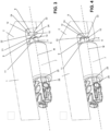
- the toilet cover 1 comprises at least one toilet cover element 2 and at least one hinge element 3.
- the at least one toilet cover element 2 can be pivotally connected to a sanitary article, such as a toilet bowl, via the at least one hinge element 3.
- the hinge element 3 has a fastening interface for this purpose, which is not shown in the figures.
- the toilet support element 2 can be a toilet seat ring or a toilet lid or the combination thereof. In the embodiment shown, the combination of toilet seat ring and toilet lid is shown.
- the hinge element 3 has a hinge receptacle 4 and a hinge pin 5 with a bearing section 6 and a pivot section 7, which is pivotably mounted in the hinge receptacle 4.
- the pivot section 7 extends into a pivot opening 27 in the hinge receptacle 4. This means that the hinge pin 5 can pivot relative to the fixed hinge receptacle 4.
- the hinge receptacle 4 is part of the aforementioned fastening interface or the hinge receptacle 4 is connected to the aforementioned fastening interface.
- the fastening interface not shown in the figures serves to attach the hinge receptacle 4 to a toilet bowl.
- the at least one toilet support element 2 has at least one bearing opening 8 into which the bearing section 6 projects.
- the cross section of the bearing opening 8 and the cross section of the bearing section 6 of the hinge pin 5 are preferably designed to be complementary, so that the bearing section 6 can be inserted into the bearing opening 8 and essentially fills the bearing opening 8.
- the bearing opening 8 is arranged in the toilet lid.
- the toilet seat ring also shown in the figures has a continuous opening 25 through which the hinge pin 5 extends.
- the bearing section 6 lies on one side of this opening 25 and the pivot section 7 lies on the other side of this opening 25.
- the hinge pin 5 has a bearing point 26 which comes to lie in the opening 25.
- the bearing point 26 lies between the bearing section 6 and the pivot section 7. If there is no toilet seat ring, the bearing point 26 is preferably not present.
- the bearing section 6 and the bearing opening 8 each have a bearing surface 9, 10 with at least one surface section 11, 12.
- the at least one surface section 11, 12 is designed in such a way that an alignment of the hinge pin 5 with respect to a rotation about its central axis M relative to the bearing opening 8 is assumed.
- two surface sections 11, 12 are arranged, which run parallel to one another and are designed as flat surfaces. One of the surface sections 11 comes into contact with another of the surface sections 12.
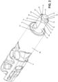
- the bearing section 6 has at least one alignment edge 14.
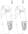
- the alignment edge 14 is designed such that when the bearing section 6 is pushed into the bearing opening 8, the hinge pin 5 pivots about its central axis M, so that the at least one surface section 11 of the bearing section 6 can be aligned relative to the at least one surface section 12 of the bearing opening 8. This alignment ensures that the hinge pin 5 is positioned relative to the bearing opening 8 in such a way that the bearing section 6 can be pushed into the bearing opening 8.
- the alignment edge 14 is designed such that the hinge pin 5 pivots automatically and continuously as it moves into the bearing opening 8.
- the preferred alignment edge 14 is shown in the Figure 2 shown.
- the alignment edge 14 extends from a front edge 15 to a rear edge 16, wherein the rear edge 16 is set back relative to the front edge 15 in the insertion direction.
- the front edge 15 as well as the rear edge 16 extend at right angles and at a distance from the central axis M of the hinge pin 5.
- two alignment edges 14 are present, wherein the front edges 15 and the rear edges 16 each extend parallel to one another.
- the front edge 15 of the one alignment edge 14 runs collinearly to the rear edge 16 of the other alignment edge 14.
- the hinge pin 5 has an inner edge 17 which runs with a slope on a circular cylinder 18 which extends around the central axis M.
- the inner edge 17 connects an inner end of the front edge 15 with an inner end of the rear edge 16.
- the alignment edge 14 connects an outer end of the front edge 15 with an outer end of the rear edge 16.
- the slope of the alignment edge 14 is preferably constant.
- the slope of the inner edge 17 is different here to the slope of the alignment edge 14; however, the slope can also be the same. In other words, it can also be said that the alignment edge 14 extends essentially in a helical manner around the central axis M.
- the alignment edge 14, the inner edge 17, the front edge 15 and the rear edge 16 delimit a surface 19.
- a tenon extension 21 extends from the at least one alignment edge 14 at the front in the direction of the central axis M.
- the tenon extension 21 has the shape of a circular cylinder.
- the above-mentioned inner edge 17 runs on the outer surface of the tenon extension 21.
- the bearing section 6 and the bearing opening 8 have at least one cylindrical, in particular a circular cylindrical, surface 23, 24, which adjoins the at least one surface section 11, 12 on the peripheral side.
- one of the surfaces 23, 24 is arranged between the surface sections 11, 12 on the top and bottom.
- the alignment edge 14 described above lies on the surface 23.
- the bearing surface 10 of the bearing opening 8 has an edge 22 at the front end of the bearing opening 8 or defines an edge 22.
- the at least one alignment edge 14 can be brought into contact with this edge 22 during the insertion process. The alignment between the bearing section 6 and the bearing opening 8 takes place via this contact.
- the alignment edge 14 is in contact with the edge 22.
- the hinge pin 5 is further aligned due to the interaction between the alignment edge 14 and the edge 22.
- the alignment takes place as a pivoting around the central axis M.
Landscapes
- Health & Medical Sciences (AREA)
- Public Health (AREA)
- Toilet Supplies (AREA)
Priority Applications (1)
| Application Number | Priority Date | Filing Date | Title |
|---|---|---|---|
| EP23180635.7A EP4480366A1 (fr) | 2023-06-21 | 2023-06-21 | Support de toilettes |
Applications Claiming Priority (1)
| Application Number | Priority Date | Filing Date | Title |
|---|---|---|---|
| EP23180635.7A EP4480366A1 (fr) | 2023-06-21 | 2023-06-21 | Support de toilettes |
Publications (1)
| Publication Number | Publication Date |
|---|---|
| EP4480366A1 true EP4480366A1 (fr) | 2024-12-25 |
Family
ID=86942179
Family Applications (1)
| Application Number | Title | Priority Date | Filing Date |
|---|---|---|---|
| EP23180635.7A Pending EP4480366A1 (fr) | 2023-06-21 | 2023-06-21 | Support de toilettes |
Country Status (1)
| Country | Link |
|---|---|
| EP (1) | EP4480366A1 (fr) |
Citations (2)
| Publication number | Priority date | Publication date | Assignee | Title |
|---|---|---|---|---|
| DE102019105939A1 (de) * | 2018-10-08 | 2020-04-09 | Hamberger Industriewerke Gmbh | Rotationsdämpfer und WC-Sitzgarnitur |
| EP3831258A1 (fr) * | 2019-12-06 | 2021-06-09 | Geberit International AG | Charnière de montage d'une protection des toilettes |
-
2023
- 2023-06-21 EP EP23180635.7A patent/EP4480366A1/fr active Pending
Patent Citations (2)
| Publication number | Priority date | Publication date | Assignee | Title |
|---|---|---|---|---|
| DE102019105939A1 (de) * | 2018-10-08 | 2020-04-09 | Hamberger Industriewerke Gmbh | Rotationsdämpfer und WC-Sitzgarnitur |
| EP3831258A1 (fr) * | 2019-12-06 | 2021-06-09 | Geberit International AG | Charnière de montage d'une protection des toilettes |
Similar Documents
| Publication | Publication Date | Title |
|---|---|---|
| DE3049241C2 (fr) | ||
| DE3612878C2 (fr) | ||
| DE19728641A1 (de) | Positionsscharnier für Türen | |
| DE10329959A1 (de) | Halter für einen Getränkebehälter | |
| EP3797661B1 (fr) | Cheville à bascule | |
| CH713878A2 (de) | Sitzbaugruppe mit einer Armlehne, die einen Armlehnendeckel und eine Gelenkanordnung aufweist. | |
| AT521373A4 (de) | Anordnung zur Führung einer Schiebetür | |
| DE3709403C2 (fr) | ||
| DE3808585A1 (de) | Schnaepperscharnier fuer moebeltueren | |
| DE19936280A1 (de) | Türscharniersystem | |
| DE10297096T5 (de) | Scharnierkonstruktion und Scharnierbetätigungsvorrichtung, insbesondere für einen Seitenspiegel eines Motorfahrzeugs | |
| DE102009014084B4 (de) | Scharnier für einen Kraftwagen | |
| DE8212789U1 (de) | Schere | |
| DE2340762A1 (de) | Scharnier | |
| DE69012136T2 (de) | Scharnier für flügeltüren bei kühlschränken. | |
| DE112014006955T5 (de) | Türschanier höhenverstellvorrichtung für eine drehende tür | |
| EP0777025A1 (fr) | Charnière pour porte de véhicule avec fonction de retenue et de freinage | |
| DE102009045888B4 (de) | Haushaltsgerät | |
| DE7612958U1 (de) | Absperrventil | |
| DE3109553A1 (de) | Haltevorrichtung fuer eine schwenktuer | |
| DE3304472A1 (de) | Geschlossenes, beidseitig verschwenkbares und sich selbst rueckstellendes drehgelenk, insbesondere fuer tueren | |
| DE19509104C2 (de) | Trennbares Scharnier für Kraftwagen | |
| DE3304458A1 (de) | Geschlossenes, sich selbst rueckstellendes drehgelenk | |
| DE1580609A1 (de) | Sitzgestell,insbesondere fuer Kraftfahrzeuge | |
| DE10105364A1 (de) | Lager für eine Lehne eines Sitzes |
Legal Events
| Date | Code | Title | Description |
|---|---|---|---|
| PUAI | Public reference made under article 153(3) epc to a published international application that has entered the european phase |
Free format text: ORIGINAL CODE: 0009012 |
|
| STAA | Information on the status of an ep patent application or granted ep patent |
Free format text: STATUS: THE APPLICATION HAS BEEN PUBLISHED |
|
| AK | Designated contracting states |
Kind code of ref document: A1 Designated state(s): AL AT BE BG CH CY CZ DE DK EE ES FI FR GB GR HR HU IE IS IT LI LT LU LV MC ME MK MT NL NO PL PT RO RS SE SI SK SM TR |
|
| STAA | Information on the status of an ep patent application or granted ep patent |
Free format text: STATUS: REQUEST FOR EXAMINATION WAS MADE |
|
| 17P | Request for examination filed |
Effective date: 20250411 |