EP4480761A2 - Enrouleur de ceinture - Google Patents
Enrouleur de ceinture Download PDFInfo
- Publication number
- EP4480761A2 EP4480761A2 EP24211294.4A EP24211294A EP4480761A2 EP 4480761 A2 EP4480761 A2 EP 4480761A2 EP 24211294 A EP24211294 A EP 24211294A EP 4480761 A2 EP4480761 A2 EP 4480761A2
- Authority
- EP
- European Patent Office
- Prior art keywords
- belt
- belt retractor
- tube
- retractor
- reel
- Prior art date
- Legal status (The legal status is an assumption and is not a legal conclusion. Google has not performed a legal analysis and makes no representation as to the accuracy of the status listed.)
- Granted
Links
Images




Classifications
-
- B—PERFORMING OPERATIONS; TRANSPORTING
- B60—VEHICLES IN GENERAL
- B60R—VEHICLES, VEHICLE FITTINGS, OR VEHICLE PARTS, NOT OTHERWISE PROVIDED FOR
- B60R22/00—Safety belts or body harnesses in vehicles
- B60R22/34—Belt retractors, e.g. reels
- B60R22/46—Reels with means to tension the belt in an emergency by forced winding up
- B60R22/4628—Reels with means to tension the belt in an emergency by forced winding up characterised by fluid actuators, e.g. pyrotechnic gas generators
- B60R22/4633—Linear actuators, e.g. comprising a piston moving along reel axis and rotating along its own axis
-
- B—PERFORMING OPERATIONS; TRANSPORTING
- B60—VEHICLES IN GENERAL
- B60R—VEHICLES, VEHICLE FITTINGS, OR VEHICLE PARTS, NOT OTHERWISE PROVIDED FOR
- B60R22/00—Safety belts or body harnesses in vehicles
- B60R22/34—Belt retractors, e.g. reels
- B60R22/46—Reels with means to tension the belt in an emergency by forced winding up
- B60R22/4628—Reels with means to tension the belt in an emergency by forced winding up characterised by fluid actuators, e.g. pyrotechnic gas generators
- B60R22/4633—Linear actuators, e.g. comprising a piston moving along reel axis and rotating along its own axis
- B60R2022/4638—Linear actuators, e.g. comprising a piston moving along reel axis and rotating along its own axis comprising a piston moving along or in parallel to the reel axis
-
- B—PERFORMING OPERATIONS; TRANSPORTING
- B60—VEHICLES IN GENERAL
- B60R—VEHICLES, VEHICLE FITTINGS, OR VEHICLE PARTS, NOT OTHERWISE PROVIDED FOR
- B60R22/00—Safety belts or body harnesses in vehicles
- B60R22/34—Belt retractors, e.g. reels
- B60R22/46—Reels with means to tension the belt in an emergency by forced winding up
- B60R22/4628—Reels with means to tension the belt in an emergency by forced winding up characterised by fluid actuators, e.g. pyrotechnic gas generators
- B60R2022/4642—Reels with means to tension the belt in an emergency by forced winding up characterised by fluid actuators, e.g. pyrotechnic gas generators the gas directly propelling a flexible driving means, e.g. a plurality of successive masses, in a tubular chamber
Definitions
- the present invention relates to a belt retractor having the features of the preamble of claim 1.
- the basic components of belt retractors are a load-bearing frame and a belt reel that is rotatably mounted in the frame and onto which a safety belt can be wound.
- the frame In addition to supporting the belt reel, the frame is also used to attach it to a seat structure or a vehicle structure and is made from a suitably thick sheet steel that is bent into a U-shaped frame.
- Vehicle seats with safety belt devices are known, for example, for use as front seats in convertibles, where at least the belt retractors of the safety belt devices are attached to the backrests of the vehicle seats.
- the belt retractors are preferably integrated into the backrests of the vehicle seats due to the lack of a load-bearing B-pillar and for reasons of access to the rear seats or for reasons of distance from the rear vehicle structure, which must therefore also be designed to absorb the tensile forces acting in the event of restraint.
- the belt retractors themselves have all the basic components of a standard belt retractor and are only provided with various additional components specifically designed for installation in the backrest, such as a self-aligning inertia sensor or a sensor shutdown device.
- the basic design of the vehicle seat consists of a seat structure made up of several load-bearing structural parts which serve to attach the vehicle seat to the vehicle structure.
- the seat structure is equipped with springs to improve seating comfort. and upholstery and is also used to attach other components such as various seat adjustment mechanisms, including the associated electric motors and other components such as heating devices, sensors, displays, headrests and the like.
- the belt retractor and its other components require a relatively large amount of space due to their external dimensions, so that installation in the vehicle seat can be problematic. This is particularly due to the fact that the seat belt must have a certain minimum thickness to absorb the tensile forces with a given width of e.g. 46 mm and a certain minimum length of e.g. 2500 mm to restrain the occupant, so that the belt wrap on the belt reel has a correspondingly large external diameter when the seat belt is fully wound up due to the volume of the seat belt to be wound up.
- the object of the invention is to provide a belt retractor with an irreversible belt tensioner, which can also be arranged in a limited installation space of a vehicle seat.
- the belt retractor has at least one web which is arranged perpendicular to the axis of rotation of the belt reel and serves to support the belt retractor and/or to accommodate other components of the belt retractor.
- the web allows the belt retractor to be made longer without this impairing the bearing.
- the web can also be used alternatively or additionally to accommodate or hold other components.
- the belt retractor has a frame to which the webs are fixed, and that the tube is fixed between the webs and the frame.
- the two housing shells can each have partial receptacles which complement each other to form a receptacle in which the drive device is guided at least in sections and/or in which the pipe is held in sections.
- the housing shells thus form the holder for the pipe and/or a guide for the drive device before and during the engagement movement in the drive wheel. If the housing shells together also form the receptacle for the drive wheel, the proposed solution is particularly advantageous because the drive device is thereby guided in a fixed spatial arrangement on the drive wheel.
- the drive device is formed by a plurality of mass bodies that are loosely adjacent to one another, and that a collecting container is provided in which the mass bodies are received after the belt tensioner has been activated.
- the collecting container serves to store the mass bodies after they have passed through the drive wheel and thus prevents a subsequent function of the belt retractor from being disrupted by freely and uncontrollably moving mass bodies.
- the collecting container can preferably be arranged on the web, so that the web is also used to hold the collecting container.
- the collecting container can also be integrally formed in the form of a hollow space on the web or on one of the housing shells. If the web simultaneously forms the holder for the drive wheel and the guide for the drive device, the proposed further development is particularly advantageous, since the mass bodies are thereby discharged into the collecting containers in a fixed spatial arrangement after passing through the drive wheel.
- the housing shells or the web thus form a complete guide path for the mass bodies, starting from the feed from the pipe, through the passage through the drive wheel to the discharge into the collecting container.
- the tube has a free end which is aligned parallel to the axis of rotation of the belt reel, wherein a gas generator is held in the free end, or it is proposed that the tube has a free end which is perpendicular to the axis of rotation of the belt reel is aligned, with a gas generator held in the free end.
- the proposed solutions allow the gas generator to be aligned and mounted either parallel to the belt reel's axis of rotation or perpendicular to the belt reel's axis of rotation. This means that no sharp edges are created inside or on the seat structure and the arrangement of the belt tensioner allows sufficient distance from the vehicle occupant so that sufficiently thick padding of the vehicle seat is possible between the belt tensioner and the occupant.
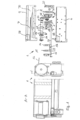
- a belt retractor 1 according to the invention can be seen in individual parts and in an assembled state.
- the belt retractor 1 comprises as a basic component a profile rail 7 which is U-shaped in cross section, with a base surface 10 and two opposite, parallel wall-shaped legs 8 and 9 which protrude from the base surface 10.
- the profile rail 7 has an opening 28 in the base surface 10 and in the upper leg 8 in the illustration, through which a safety belt 12 which can be seen in the left-hand illustration is led out to the outside.
- a cavity 21 is formed between the legs 8, 9 and the base surface 10 of the profile rail 7, in which the components of the belt retractor 1 are arranged and which is closed by an insert part 6.
- the components of the belt retractor include a belt reel 14, a force limiting device 25, an irreversible belt tensioner 24, several webs 15, 16, 17, 18, 19 and 20 and various additional parts, such as additional sensors, control units and electrical lines which are not shown for a better representation of the invention. Furthermore, a reversible belt tensioner or a belt feeder can also be provided.
- the webs 15, 16, 17, 18, 19 and 20 are supported between the legs 8, 9, the base surface 10 and, when the cavity 21 is closed, on the insert part 6 and form the bearing and holder for the belt retractor 1 or in particular for the belt reel 14 and the other rotating parts.
- the external dimensions of the belt reel 14 with the safety belt 12 wound up to the maximum, as well as the external dimensions of the force limiting device 25 and the pyrotechnic belt tensioner 24 are selected in the cross-sectional area perpendicular to the axis of rotation of the belt reel 14 so that they are not larger than the external dimensions of the belt roll on the belt reel 14 with the safety belt 12 wound up to the maximum. Furthermore, the external dimensions are not larger than the dimensions of the cavity 21 perpendicular to the longitudinal extension of the profile rail 7, so that the belt retractor 1 with the components can be arranged in the cavity 21 of the profile rail 7.
- the webs 15, 16, 17, 18, 19 and 20 are designed in the form of wall sections aligned perpendicular to the longitudinal extension of the profile rail 7, which extend from one of the legs 8 or 9 to the other leg 8 or 9 of the profile rail 7 and are connected to them. Furthermore, the webs 15, 16, 17, 18, 19 and 20 can extend to the base surface 10 of the profile rail 7 and thus fill the entire cross-sectional area of the profile rail 7.
- the webs 15, 16, 17, 18, 19 and 20 each have one or more openings or projections in which the belt retractor 1 or parts thereof such as the belt reel 14 are mounted, fastened and/or guided through.
- one of the webs 15, 16, 17, 18, 19 and 20 can also have a toothing or another type of blocking design in which the belt reel 14 or other parts of the belt retractor can be blocked.
- the webs 15, 16, 17, 18, 19 and 20 can also have additional cavities for accommodating other components of the belt retractor, such as pyrotechnic propellants for the pyrotechnic belt tensioner 24, electronic components such as sensors, electronic control units or storage units. If the webs 15, 16, 17, 18, 19 and 20 extend from a the legs 8 or 9 extend to the other leg 8 or 9, the webs 15, 16, 17, 18, 19 and 20 can also be used to stiffen the profile rail 7, which in turn is advantageous for the load bearing and the dimensional stability of the profile rail 7 when the occupant is restrained.
- the components of the belt retractor 1 are deliberately arranged coaxially and one behind the other so that the assemblies do not increase the external dimensions of the belt retractor radially outwards, and the belt retractor 1 can also be arranged in the narrow, elongated cavity 21 of the profile rail 7.
- the profile rail 7 together with the insert part 6 forms a frame with an elongated hollow space 21 with a square cross-section. Since the belt reel 14 with the safety belt 12 wound on it and the other components are circular in cross-section, an elongated free space with an approximately triangular cross-section is provided in the corners between the belt winding of the belt reel 14, the components and the profile rail 7 and the insert part 6, which is used here to arrange a tube 32 of the pyrotechnic irreversible belt tensioner 24.
- the tube 32 serves to guide a drive device, such as a chain of loosely adjacent mass bodies, or an elastic drive train, which is accelerated when the pyrotechnic belt tensioner 24 is activated and is thereby brought into drive connection with a drive wheel 35.
- the drive wheel 35 is connected to the belt reel 14 in a rotationally fixed manner via a toothing or a polygonal profile, so that the belt reel 14 is driven by the drive movement via the drive wheel 35 to a rotational movement in the winding direction of the safety belt 12, and the safety belt 12 is tightened.
- the tube 32 has a linear section 33 and a curved section 34. and is aligned and arranged such that it is arranged with the linear section 33 parallel to the axis of rotation of the belt reel 14 and the longitudinal axis of the force limiting device 25.
- the linear section 33 is dimensioned so long that it extends from the free end held on the left web 15 to the side of the belt reel 14 and to the side of the force limiting device 25 and in the process fills a triangular free space between the belt reel and the lower leg 8 in the illustration and the insert part 6.
- the curved section 34 is shaped such that the drive device is diverted from the linear movement in the linear section 33 in the direction of a circumferential movement in the drive wheel 35.
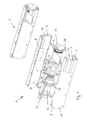
- the belt retractor 1 can be seen without the profile rail 7 only with the insert part 6 and the components.
- the additional profile rail 7 and the insert part 6 together form a frame for the belt retractor 1, which covers the components of the belt retractor 1 on the outside and forms the holder for the webs 15, 16, 17, 18, 19 and 20.
- the tube 32 with the linear section 33 is secured against slipping sideways in three recesses 36, 37 and 38 of the webs 18, 17 and 15 and is then covered on the outside by the frame, which is formed by the additional profile rail 7.
- the tube 32 is thus fixed with the linear section 33 between the webs 18, 17 and 15 and the lower leg 8 of the profile rail 7.
- the web 19 can be seen in an enlarged view.
- the web 19 is formed by two housing shells 2 and 3, each with a cover plate 4 and 5, whereby the cover plate 5 is only in the Figure 1
- the housing shells 2 and 3 each have a circular partial receptacle 27 and 28 with a quarter-circular radius in cross-section, which in the assembled form of the housing shells 2 and 3 complement each other to form a receptacle 26 for the drive wheel 35 with a circumferential guide for the drive device that is semicircular in cross-section.
- the housing shells 2 and 3 each have a further partial receptacle 22 and 23, which in the assembled form of the housing shells 2 and 3 form a guide channel for the drive device.
- the partial receptacles 22 and 23 each comprise a curved transition section 31 on the inlet side, which is shaped such that the pipe 32 with its free end passes tangentially therein or is held tangentially therein.
- the transition sections 31 extend from the planes of the housing shells 2 and 3 in the direction of the pipe 32 and together form a curved inlet channel with a curvature corresponding to the curvature of the adjacent pipe 32.
- the partial receptacles 22 and 23 are shaped such that in the assembled form they form a guide channel directed tangentially towards the outer circumference of the drive wheel 35 and on the outlet side they form a guide channel leading tangentially away from the drive wheel 35.
- the cover plate 4 on the left in the illustration has a cavity which forms a collecting container 29 for receiving the drive device, e.g. the loose mass body after passing through the drive wheel 35.
- the web 19 thus forms the receptacle 26 for the drive wheel 35 through the assembled housing shells 2 and 3 with the cover plate 4 and also a complete guide and reception of the drive device starting from the outlet from the pipe 32 to a discharge into the collecting container in a fixed spatial assignment to the drive wheel 35.
- the housing shells 2 and 3 are realized as solid block-like walls with a complex shape by the partial receptacles 22, 23, 27 and 28 and can be realized, for example, in the form of a plastic injection-molded part, while the cover plates 4 and 5 are each formed by a metal stamped part.
- a further holding plate 21 is provided on the right-hand cover plate 5, which is also supported on the profile rail 7 and the cover part 6 and serves, among other things, to hold a vehicle-sensitive sensor.
- the linear section 33 of the tube 32 is dimensioned and arranged so long that it extends parallel to the axis of rotation of the belt reel 14 over the entire longitudinal side of the belt reel 14 and parallel to the axis of rotation or longitudinal axis of the force limiting device 25 over the entire length of the force limiting device 25.
- the length is preferably 7 to 15 cm and enables a very high linear acceleration of the drive device in the initial phase of the activation of the irreversible belt tensioner 25 before the drive device engages the drive wheel 35.
- the guidance and accommodation of the drive device and the drive wheel 35 in the web 19 is an independent invention.
- the proposed guidance and accommodation of the drive device and the drive wheel 35 in the web 19 enables very precise guidance and alignment of the drive device to the drive wheel 35 due to the fixed spatial allocation.
- the guidance can be implemented particularly cost-effectively by Web 19 is made from two housing shells 2 and 3 with the partial receptacles 22, 23, 27 and 28 provided therein, e.g. as a plastic injection-molded part, which then, when put together, form the receptacle 26 and the guide for the drive wheel 35 and the drive device.
- the housing shells 2 and 3 form the guide of the drive device to the drive wheel 35, while the drive wheel 35 passes through and also when the drive wheel 35 is discharged into the collecting container 29.
- the web 19 with the two housing shells 2 and 3 therefore has a thickness which corresponds at least to the width of the drive device. Due to the necessary large width of the web 19, it also provides additional stiffening of the frame formed by the combination of the profile rail 7 and the insert part 6.
- the web 19 has all parts of the guide of the drive device including the collecting container 29 and can be pre-assembled as an assembly and then inserted into the profile rail 7.
- the drive wheel 35 then only has to be inserted into the holder 26 either already in the position connected to the belt reel 14 or as an individual part.
- the tube 32 has the gas generator 11 held therein at its left free end and is fixed with the free end to the left front web 15 of the belt retractor 1 against the direction of pull from the belt retractor 1, so that the tube 32 is supported on the inside of the web 15 when the gas generator 11 is activated and the reaction forces are passed on to the frame of the belt retractor 1.
- the belt retractor 1 additionally has a reversible belt tensioner with an electric motor 36 and a gear 37, which can also be designed to implement other functions such as adjusting the retraction force exerted on the belt reel 14 for comfort purposes or to help wind the seat belt into the parking position.
- the electric motor 36 and the gear 37 are arranged coaxially and in series with the belt reel 14, whereby a very slim and elongated design of the belt retractor 1 can be achieved, e.g. for arranging the belt retractor 1 in very narrow installation spaces in the vehicle structure or a vehicle seat.
- the tube 32 of the irreversible belt tensioner 25 is aligned here such that the linear section 33 extends parallel to the axis of rotation of the belt reel 14 and away from the belt reel 14.
- the length of the linear section 33 is dimensioned such that it extends to the side of the gear 37 and the electric motor 37, utilizing the free space available in the corner of the profile rail 7, and is thus dimensioned as long as possible.
- the drive device guided in the tube 32 is thus accelerated linearly and in a straight line over as long a path as possible before it comes to engage the drive wheel 35 to transmit the drive movement.
- Both described embodiments have in common that the components of the belt retractor 1, such as the belt reel 14, force limiting device 25 and drive wheel 35, and in the second embodiment the gear 37 and the electric motor 36 are arranged coaxially to the axis of rotation of the belt reel 14 and in series with the belt reel 14, so that the belt retractor 1 is as long and narrow as possible.
- This advantageous elongated basic structure of the belt retractor 1 is now used to provide the tube 32 with the longest possible linear section 33, which is then parallel to the axis of rotation of the belt reel 14 and to the side of the belt reel 14 and a further assembly such as the force limiting device 25 or to the side of the gear 37 and the electric motor 37.
- a free installation space in one of the corners of the profile rail 7 is advantageously used for the arrangement of the linear section 33 of the tube 32.
- the belt retractor 1 corresponds in its basic structure to that shown in the Figure 4 shown belt retractor 1, so that in this respect the Figure 4
- the embodiment of the Figures 5 and 6 differs from the embodiment of the Figure 4 in that the free end 13 of the tube 32 in which the gas generator 11 is held is angled at an angle of approximately 30 to 90 degrees relative to the axis of rotation of the belt spool 14.
- the belt retractor 1 also has two fastening lugs 40 and 41 which protrude perpendicularly to the axis of rotation of the belt spool 14 and via which the belt retractor 1 can be fastened to a vehicle seat (not shown).
- the belt retractor 1 is preferably fastened to the top of the vehicle seat via the fastening lugs 40 and 41 so that the seat belt leading out of the belt retractor 1 is fed to the occupant over the shoulder.
- the free end 13 of the tube 32 is angled such that it extends radially outwards from the belt retractor 1 between the fastening lugs 40 and 41.
Landscapes
- Engineering & Computer Science (AREA)
- Mechanical Engineering (AREA)
- Automotive Seat Belt Assembly (AREA)
Applications Claiming Priority (3)
| Application Number | Priority Date | Filing Date | Title |
|---|---|---|---|
| DE102019211852.6A DE102019211852B3 (de) | 2019-08-07 | 2019-08-07 | Gurtaufroller |
| PCT/EP2020/071076 WO2021023538A1 (fr) | 2019-08-07 | 2020-07-27 | Rétracteur de ceinture de sécurité |
| EP20753689.7A EP4010228B1 (fr) | 2019-08-07 | 2020-07-27 | Rétracteur de ceinture de sécurité |
Related Parent Applications (2)
| Application Number | Title | Priority Date | Filing Date |
|---|---|---|---|
| EP20753689.7A Division-Into EP4010228B1 (fr) | 2019-08-07 | 2020-07-27 | Rétracteur de ceinture de sécurité |
| EP20753689.7A Division EP4010228B1 (fr) | 2019-08-07 | 2020-07-27 | Rétracteur de ceinture de sécurité |
Publications (3)
| Publication Number | Publication Date |
|---|---|
| EP4480761A2 true EP4480761A2 (fr) | 2024-12-25 |
| EP4480761A3 EP4480761A3 (fr) | 2025-03-05 |
| EP4480761B1 EP4480761B1 (fr) | 2026-03-25 |
Family
ID=71995962
Family Applications (2)
| Application Number | Title | Priority Date | Filing Date |
|---|---|---|---|
| EP20753689.7A Active EP4010228B1 (fr) | 2019-08-07 | 2020-07-27 | Rétracteur de ceinture de sécurité |
| EP24211294.4A Active EP4480761B1 (fr) | 2019-08-07 | 2020-07-27 | Enrouleur de ceinture |
Family Applications Before (1)
| Application Number | Title | Priority Date | Filing Date |
|---|---|---|---|
| EP20753689.7A Active EP4010228B1 (fr) | 2019-08-07 | 2020-07-27 | Rétracteur de ceinture de sécurité |
Country Status (7)
| Country | Link |
|---|---|
| US (1) | US12168416B2 (fr) |
| EP (2) | EP4010228B1 (fr) |
| JP (1) | JP7401960B2 (fr) |
| KR (1) | KR102842710B1 (fr) |
| CN (1) | CN114174130B (fr) |
| DE (1) | DE102019211852B3 (fr) |
| WO (1) | WO2021023538A1 (fr) |
Families Citing this family (2)
| Publication number | Priority date | Publication date | Assignee | Title |
|---|---|---|---|---|
| DE102021105010B4 (de) | 2021-03-02 | 2023-02-23 | Autoliv Development Ab | Lasttragender Gurtaufroller und Sitzstruktur |
| DE102021105013A1 (de) * | 2021-03-02 | 2022-09-08 | Autoliv Development Ab | Lasttragender Gurtaufroller |
Family Cites Families (26)
| Publication number | Priority date | Publication date | Assignee | Title |
|---|---|---|---|---|
| US3096957A (en) * | 1960-11-03 | 1963-07-09 | Leslie D Peterson | Ballistic rotary actuator |
| GB1212013A (en) * | 1967-03-20 | 1970-11-11 | Teleflex Prod Ltd | Improvements in or relating to safety harness reels |
| US5924640A (en) * | 1995-02-16 | 1999-07-20 | Royal Ordnance Public Limited Company | Vehicle occupant restraint system |
| JP4654489B2 (ja) * | 2000-06-16 | 2011-03-23 | タカタ株式会社 | シートベルト巻取装置 |
| US6547273B2 (en) | 2000-10-05 | 2003-04-15 | Simula, Inc. | Inflatable seat restraint system using an inflation integrated inertia reel |
| DE10204477B4 (de) * | 2002-02-05 | 2006-11-30 | Daimlerchrysler Ag | Gurtstraffer |
| US6811186B1 (en) * | 2002-03-29 | 2004-11-02 | Lear Corporation | Seat belt adjustment mechanism |
| JP3972736B2 (ja) * | 2002-06-04 | 2007-09-05 | タカタ株式会社 | 乗員保護装置 |
| JP4297336B2 (ja) | 2003-08-07 | 2009-07-15 | タカタ株式会社 | シートベルトリトラクタおよびこれを備えたシートベルト装置 |
| AU2003263382A1 (en) * | 2003-09-16 | 2005-04-06 | Autoliv Ifb India Pvt Ltd | A web spool tightener |
| WO2006109106A1 (fr) * | 2005-04-14 | 2006-10-19 | Carlo La Corte | Dispositif permettant la liberation rapide d'une ceinture de securite |
| DE102007043863A1 (de) * | 2007-09-14 | 2009-03-26 | Trw Automotive Gmbh | Gurtaufroller |
| FR2928320B1 (fr) * | 2008-03-04 | 2011-08-19 | Peugeot Citroen Automobiles Sa | Systeme de fixation d'un enrouleur de securite et d'autres organes de securite a une partie rigide de la caisse d'un vehicule automobile. |
| JP5261736B2 (ja) | 2008-09-16 | 2013-08-14 | タカタ株式会社 | シートベルトリトラクタおよびこれを備えたシートベルト装置 |
| US20100176236A1 (en) * | 2009-01-09 | 2010-07-15 | Autoliv Asp, Inc. | High performance tightener |
| JP5542526B2 (ja) | 2010-05-25 | 2014-07-09 | タカタ株式会社 | シートベルトリトラクタ及びシートベルト装置 |
| DE102010051463B4 (de) * | 2010-11-17 | 2019-03-07 | Trw Automotive Gmbh | Gurtstraffer für ein Sicherheitsgurtsystem |
| US9440617B2 (en) * | 2013-03-15 | 2016-09-13 | Autoliv Asp, Inc. | Seatbelt pretensioner |
| JP6421003B2 (ja) * | 2014-09-22 | 2018-11-07 | Joyson Safety Systems Japan株式会社 | プリテンショナ、リトラクタ及びシートベルト装置 |
| DE102014114140B4 (de) * | 2014-09-29 | 2017-01-05 | Autoliv Development Ab | Gurtaufroller mit zweiteiligem Strafferantriebsrad |
| JP2017159843A (ja) * | 2016-03-11 | 2017-09-14 | タカタ株式会社 | プリテンショナ、リトラクタ及びシートベルト装置 |
| JP2017218084A (ja) * | 2016-06-09 | 2017-12-14 | 株式会社東海理化電機製作所 | ウェビング巻取装置 |
| KR102596240B1 (ko) * | 2016-12-13 | 2023-11-01 | 현대자동차주식회사 | 프리텐셔너 및 이를 갖춘 안전벨트장치 |
| JP6871037B2 (ja) | 2017-03-27 | 2021-05-12 | Joyson Safety Systems Japan株式会社 | シートベルトリトラクタ及びシートベルト装置 |
| DE102017111398A1 (de) * | 2017-05-24 | 2018-11-29 | Trw Automotive Gmbh | Gurtaufroller und Verfahren zur Steuerung eines Gurtaufrollers |
| US10723310B2 (en) | 2018-01-26 | 2020-07-28 | Autoliv Asp, Inc. | Seatbelt pretensioning retractor assembly |
-
2019
- 2019-08-07 DE DE102019211852.6A patent/DE102019211852B3/de active Active
-
2020
- 2020-07-27 WO PCT/EP2020/071076 patent/WO2021023538A1/fr not_active Ceased
- 2020-07-27 EP EP20753689.7A patent/EP4010228B1/fr active Active
- 2020-07-27 JP JP2022507471A patent/JP7401960B2/ja active Active
- 2020-07-27 CN CN202080053662.9A patent/CN114174130B/zh active Active
- 2020-07-27 US US17/633,068 patent/US12168416B2/en active Active
- 2020-07-27 KR KR1020227007006A patent/KR102842710B1/ko active Active
- 2020-07-27 EP EP24211294.4A patent/EP4480761B1/fr active Active
Also Published As
| Publication number | Publication date |
|---|---|
| EP4010228B1 (fr) | 2025-04-23 |
| JP2022543290A (ja) | 2022-10-11 |
| DE102019211852B3 (de) | 2020-12-10 |
| EP4010228A1 (fr) | 2022-06-15 |
| JP7401960B2 (ja) | 2023-12-20 |
| US12168416B2 (en) | 2024-12-17 |
| CN114174130B (zh) | 2023-12-15 |
| KR20220038777A (ko) | 2022-03-29 |
| EP4480761A3 (fr) | 2025-03-05 |
| EP4480761B1 (fr) | 2026-03-25 |
| CN114174130A (zh) | 2022-03-11 |
| KR102842710B1 (ko) | 2025-08-06 |
| WO2021023538A1 (fr) | 2021-02-11 |
| US20220266792A1 (en) | 2022-08-25 |
Similar Documents
| Publication | Publication Date | Title |
|---|---|---|
| EP3964405B1 (fr) | Partie structurale portante pour un siège de véhicule | |
| EP3833583B1 (fr) | Enrouleur de ceinture | |
| EP3268260A1 (fr) | Colonne de direction pour un véhicule automobile | |
| EP4301631B1 (fr) | Enrouleur de ceinture de transport de charge et structure du siège | |
| DE10119753B4 (de) | Gurtstraffer | |
| DE102020207535A1 (de) | Gurtaufroller | |
| DE102018218293A1 (de) | Gurtaufroller | |
| EP4480761B1 (fr) | Enrouleur de ceinture | |
| DE60204890T2 (de) | Aufroller | |
| EP4211004B1 (fr) | Rétracteur de ceinture | |
| EP1689623B1 (fr) | Ensemble retracteur/pretensionneur de ceinture de securite | |
| EP4065426B1 (fr) | Enrouleur de ceinture de sécurité | |
| DE102020207557B3 (de) | Gurtaufroller | |
| DE602006000439T2 (de) | Sicherheitsgurt-Aufroller und Sicherheitsgurtvorrichtung mit einem derartigen Sicherheitsgurt-Aufroller | |
| DE602006000151T2 (de) | Sicherheitsgurt-Aufroller und Sicherheitsgurtvorrichtung mit einem derartigen Sicherheitsgurt-Aufroller | |
| DE102022101082B4 (de) | Gurtaufroller | |
| EP4211005B1 (fr) | Enrouleur de ceinture | |
| DE3229260C2 (de) | Rückstrammer für ein Sicherheitsgurtsystem für Kraftfahrzeuge | |
| DE102022101080B4 (de) | Gurtaufroller | |
| DE102010049012B4 (de) | Sicherheitsgurteinrichtung für ein Kraftfahrzeug | |
| DE102022130542A1 (de) | Gurtaufroller mit einer Straffeinrichtung | |
| WO2019105902A1 (fr) | Rétracteur de ceinture | |
| DE10319718A1 (de) | Verbindungsanordnung an einem Gurtaufwickelautomaten mit einer Gurtstraffvorrichtung |
Legal Events
| Date | Code | Title | Description |
|---|---|---|---|
| PUAI | Public reference made under article 153(3) epc to a published international application that has entered the european phase |
Free format text: ORIGINAL CODE: 0009012 |
|
| STAA | Information on the status of an ep patent application or granted ep patent |
Free format text: STATUS: THE APPLICATION HAS BEEN PUBLISHED |
|
| AC | Divisional application: reference to earlier application |
Ref document number: 4010228 Country of ref document: EP Kind code of ref document: P |
|
| AK | Designated contracting states |
Kind code of ref document: A2 Designated state(s): AL AT BE BG CH CY CZ DE DK EE ES FI FR GB GR HR HU IE IS IT LI LT LU LV MC MK MT NL NO PL PT RO RS SE SI SK SM TR |
|
| PUAL | Search report despatched |
Free format text: ORIGINAL CODE: 0009013 |
|
| AK | Designated contracting states |
Kind code of ref document: A3 Designated state(s): AL AT BE BG CH CY CZ DE DK EE ES FI FR GB GR HR HU IE IS IT LI LT LU LV MC MK MT NL NO PL PT RO RS SE SI SK SM TR |
|
| RIC1 | Information provided on ipc code assigned before grant |
Ipc: B60R 22/46 20060101AFI20250130BHEP |
|
| STAA | Information on the status of an ep patent application or granted ep patent |
Free format text: STATUS: REQUEST FOR EXAMINATION WAS MADE |
|
| 17P | Request for examination filed |
Effective date: 20250819 |
|
| GRAP | Despatch of communication of intention to grant a patent |
Free format text: ORIGINAL CODE: EPIDOSNIGR1 |
|
| STAA | Information on the status of an ep patent application or granted ep patent |
Free format text: STATUS: GRANT OF PATENT IS INTENDED |
|
| INTG | Intention to grant announced |
Effective date: 20251027 |
|
| GRAS | Grant fee paid |
Free format text: ORIGINAL CODE: EPIDOSNIGR3 |
|
| GRAA | (expected) grant |
Free format text: ORIGINAL CODE: 0009210 |
|
| STAA | Information on the status of an ep patent application or granted ep patent |
Free format text: STATUS: THE PATENT HAS BEEN GRANTED |
|
| AC | Divisional application: reference to earlier application |
Ref document number: 4010228 Country of ref document: EP Kind code of ref document: P |
|
| AK | Designated contracting states |
Kind code of ref document: B1 Designated state(s): AL AT BE BG CH CY CZ DE DK EE ES FI FR GB GR HR HU IE IS IT LI LT LU LV MC MK MT NL NO PL PT RO RS SE SI SK SM TR |
|
| REG | Reference to a national code |
Ref country code: CH Ref legal event code: F10 Free format text: ST27 STATUS EVENT CODE: U-0-0-F10-F00 (AS PROVIDED BY THE NATIONAL OFFICE) Effective date: 20260325 Ref country code: GB Ref legal event code: FG4D Free format text: NOT ENGLISH |
|
| REG | Reference to a national code |
Ref country code: DE Ref legal event code: R096 Ref document number: 502020012909 Country of ref document: DE |
|
| REG | Reference to a national code |
Ref country code: IE Ref legal event code: FG4D Free format text: LANGUAGE OF EP DOCUMENT: GERMAN |