EP4480802A1 - Pédale de bicyclette - Google Patents
Pédale de bicyclette Download PDFInfo
- Publication number
- EP4480802A1 EP4480802A1 EP23191566.1A EP23191566A EP4480802A1 EP 4480802 A1 EP4480802 A1 EP 4480802A1 EP 23191566 A EP23191566 A EP 23191566A EP 4480802 A1 EP4480802 A1 EP 4480802A1
- Authority
- EP
- European Patent Office
- Prior art keywords
- pedal
- fixing
- mentioned
- fitting
- slip nail
- Prior art date
- Legal status (The legal status is an assumption and is not a legal conclusion. Google has not performed a legal analysis and makes no representation as to the accuracy of the status listed.)
- Granted
Links
Images



Classifications
-
- B—PERFORMING OPERATIONS; TRANSPORTING
- B62—LAND VEHICLES FOR TRAVELLING OTHERWISE THAN ON RAILS
- B62M—RIDER PROPULSION OF WHEELED VEHICLES OR SLEDGES; POWERED PROPULSION OF SLEDGES OR SINGLE-TRACK CYCLES; TRANSMISSIONS SPECIALLY ADAPTED FOR SUCH VEHICLES
- B62M3/00—Construction of cranks operated by hand or foot
- B62M3/08—Pedals
- B62M3/086—Attachments between shoe and pedal other than toe clips, e.g. cleats
-
- B—PERFORMING OPERATIONS; TRANSPORTING
- B62—LAND VEHICLES FOR TRAVELLING OTHERWISE THAN ON RAILS
- B62M—RIDER PROPULSION OF WHEELED VEHICLES OR SLEDGES; POWERED PROPULSION OF SLEDGES OR SINGLE-TRACK CYCLES; TRANSMISSIONS SPECIALLY ADAPTED FOR SUCH VEHICLES
- B62M3/00—Construction of cranks operated by hand or foot
- B62M3/08—Pedals
Definitions
- the invention relates to the field of bicycle pedal, in particular to a bicycle pedal.
- clipless pedals have been developed that ensure a firm fixation with the shoe so that the shoe does not separate from the pedal with minimal force, and that clipless pedals ensure the active removal of the shoe so that the foot can rest on the ground;
- this invention provides a pedal anti-slip nail hook which is not easy to be blocked by mud.
- this invention provides a bicycle pedal.
- disassembling the traditional integrated fixed hook structure into two parts and combining with the frame type pedal body reduce the gap on the pedal that can be attached to the mud, make the pedal structure simpler and clearer, and make the components to be relatively independent, so that the mud is not easily attached to the pedal.
- a pedal including a pedal shaft and a pedal body which is rotating connected with the spindle.
- the mentioned pedal body is provided with a fixing hook mechanism and an movable hook mechanism for fixing the anti-slip nail.
- the mentioned fixing hook mechanism includes a first fixing component and a second fixing component which is fixedly attached to the mentioned pedal body.
- the mentioned second fixing component is rotating connected with the mentioned movable hook mechanism.
- the mentioned first fixing component and movable hook mechanism clamp together to fix the anti-slip nail.
- the mentioned first fixing component include a U-shaped fixing part.
- the middle part of the mentioned U-shaped fixing part is provided with a locking part for locking the anti-slip nail.
- One side of the mentioned locking part which is near the pedal shaft is provided with a first fitting curved surface to fit into the mentioned first fixing component.
- the lower side of the mentioned locking part can lock the anti-slip nail.
- the mentioned fixing part is provided with two symmetrical first supporting surfaces for supporting the anti-slip nail.
- the mentioned fixing part is also provided with a notch. Two first-connecting holes through the fixing part.
- the first bolt is passed through the mentioned first-connecting holes.
- the mentioned first bolt fixes the fixing part on the pedal body.
- the mentioned second fixing component includes installation part.
- the middle part of the mentioned installation part is provided with a second supporting surface for supporting the anti-slip nail.
- the side of the second supporting surface which is away from the pedal shaft is provided with two blocks fixed on the installation part.
- Both ends of the mentioned installation part are provided with an ear part extending downward.
- the mentioned ear part is perforated with a fixing hole.
- Both sides of the installation part are also perforated with two second-connecting holes.
- the mentioned second-connecting hole is provided with a second bolt.
- the mentioned second bolt is threaded to the pedal body and the second fixing component is fixed to the pedal body.
- the mentioned movable hook mechanism includes a connecting shaft passing through two fixing holes.
- the mentioned connecting shaft is provided with an movable cap.
- the mentioned movable cap includes two downward connecting parts and a limiting part.
- the mentioned connecting parts are provided with a through hole.
- the mentioned connecting shaft runs through the through hole.
- the side of the mentioned movable cap which is near the pedal shaft is provided with a contact surface capable of contacting the limit with the blocks.
- the middle or upper part of the mentioned movable cap is also provided with a second fitting curved surface which can be matched with the anti-slip nail.
- the lower side of the mentioned movable cap at the second fitting curved surface can lock the anti-slip nail.
- a mounting hole is run through the mentioned movable cap.
- An adjusting bolt is installed in the mentioned mounting hole.
- the mentioned adjusting bolt includes a head, a threaded part and an adjusting part.
- the mentioned adjusting part is provided with an adjusting hole in the end surface of the adjusting part.
- the mentioned adjusting part extends upward into the mounting hole.
- the mentioned threaded part through and threaded connected with the adjusting nut.
- a clamping part is arranged on one side of the adjusting nut which is away from the pedal shaft.
- a clamping hole is arranged through the limiting part to fit the clamping part. The mentioned clamping part extends into the clamping hole and restricts the rotation of the adjusting nut.
- the mentioned connecting shaft is also equipped with two springs which are positioned symmetrically between the connecting part.
- the mentioned springs include a first-end part and a second-end part.
- the mentioned first-end part abuts against the lower side of the blocks.
- the mentioned second-end abuts against the lower side of the adjusting nut.
- the anti-slip nail includes a first-locking surface for fitting the mentioned locking part, a first fitting end for fitting the first fitting curved surface, a second fitting end for fitting the second fitting curved surface, a second-locking surface which is in the lower side of the movable cap for fitting the second fitting curved surface.
- the lower side of the second fitting end is also arranged a guide surface on the anti-slip nail.
- the pedal body is provided with a first connecting arm and a second connecting arm.
- the mentioned first connecting arm, the second connecting arm and the pedal body are provided with threaded holes.
- the mentioned two threaded holes on one side of the first connecting arm are matched with the first bolt.
- the mentioned two threaded holes on one side of the second connecting arm are matched with the second bolt.
- the upper and lower sides of the pedal body are also provided with wave lines for increasing resistance.
- this invention has the following beneficial effects: by disassembling the traditional integrated fixed hook structure into two parts and combining with the frame type pedal body, reduce the gap on the pedal that can be attached to the mud, make the pedal structure simpler and clearer, and make the components to be relatively independent, so that the mud is not easily attached to the pedal.
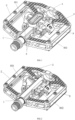
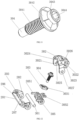
- this invention discloses a pedal, include the pedal shaft 1 and a pedal body 2 which is rotating connected with the spindle 1.
- the mentioned pedal body 2 is provided with a fixing hook mechanism 8 and an movable hook mechanism 9 for fixing the anti-slip nail 4.
- the mentioned fixing hook mechanism 8 includes a first fixing component 801 and a second fixing component 802 which is fixedly attached to the mentioned pedal body 2.
- the mentioned second fixing component 802 is rotating connected with the mentioned movable hook mechanism 9.
- the mentioned first fixing component 801 and movable hook mechanism 9 clamp together to fix the anti-slip nail 4.
- the mentioned first fixing component 801 includes a U-shaped fixing part 107.
- the middle part of the mentioned U-shaped fixing part 107 is provided with a locking part 101 for locking the anti-slip nail 4.
- One side of the mentioned locking part 101 which is near the pedal shaft 1 is provided with a first fitting curved surface 102 to fit into the mentioned first fixing component 801.
- the lower side of the mentioned locking part 101 can lock the anti-slip nail 4.
- the mentioned fixing part 107 is provided with two symmetrical first supporting surfaces 104 for supporting the anti-slip nail 4.
- the mentioned fixing part 107 is also provided with a notch 103.
- Two first-connecting holes 105 through the fixing part 107.
- the first bolt 106 is passed through the mentioned first-connecting holes 105.
- the mentioned first bolt 106 fixes the fixing part 107 on the pedal body 2.
- the mentioned second fixing component 802 includes installation part 201.
- the middle part of the mentioned installation part 201 is provided with a second supporting surface 206 for supporting the anti-slip nail 4.
- the side of the second supporting surface 206 which is away from the pedal shaft 1 is provided with two blocks 205 fixed on the installation part 201.
- Both ends of the mentioned installation part 201 are provided with an ear part 202 extending downward.
- the mentioned ear part 202 is perforated with a fixing hole 207.
- Both sides of the installation part 201 are also perforated with two second-connecting holes 203.
- the mentioned second-connecting hole 203 is provided with a second bolt 204.
- the mentioned second bolt 204 is threaded to the pedal body 2 and the second fixing component 802 is fixed to the pedal body 2.
- the mentioned movable hook mechanism 9 includes a connecting shaft 301 passing through two fixing holes 207.
- the mentioned connecting shaft 301 is provided with an movable cap 302.
- the mentioned movable cap 302 includes two downward connecting parts 3021 and a limiting part 3022.
- the mentioned connecting parts 3021 are provided with a through hole 3027.
- the mentioned connecting shaft 301 runs through the through hole 3027.
- the side of the mentioned movable cap 302 which is near the pedal shaft 1 is provided with a contact surface 3024 capable of contacting the limit with the blocks 205.
- the middle or upper part of the mentioned movable cap 302 is also provided with a second fitting curved surface 3025 which can be matched with the anti-slip nail 4.
- the lower side of the mentioned movable cap 302 at the second fitting curved surface 3025 can lock the anti-slip nail 4.
- a mounting hole 3026 is run through the mentioned movable cap 302.
- An adjusting bolt 304 is installed in the mentioned mounting hole 3026.
- the mentioned adjusting bolt 304 includes a head 3042, a threaded part 3041 and an adjusting part 3043.
- the mentioned adjusting part 3043 is provided with an adjusting hole 3044 in the end surface of the adjusting part 3043.
- the mentioned adjusting part 3043 extends upward into the mounting hole 3026.
- the mentioned threaded part 3041 through and threaded connected with the adjusting nut 303.
- a clamping part 3031 is arranged on one side of the adjusting nut 303 which is away from the pedal shaft 1.
- a clamping hole 3023 is arranged through the limiting part 3022 to fit the clamping part 3031.
- the mentioned clamping part 3031 extends into the clamping hole 3023 and restricts the rotation of the adjusting nut 303.
- the mentioned connecting shaft 301 is also equipped with two springs 305 which are positioned symmetrically between the connecting part 3021.
- the mentioned springs 305 include a first-end part 3051 and a second-end part 3052.
- the mentioned first-end part 3051 abuts against the lower side of the blocks 205.
- the mentioned second-end 3052 abut against the lower side of the adjusting nut 303.
- the anti-slip nail 4 includes a first-locking surface 402 for fitting the mentioned locking part 101, a first fitting end 401 for fitting the first fitting curved surface 102, a second fitting end 403 for fitting the second fitting curved surface 3025, a second-locking surface 404 which is in the lower side of the movable cap 302 for fitting the second fitting curved surface 3025.
- the lower side of the second fitting end 403 is also arranged a guide surface 405 on the anti-slip nail 4.
- the pedal body 2 is provided with a first connecting arm 6 and a second connecting arm 7.
- the mentioned first connecting arm 6, the second connecting arm 7 and the pedal body 2 are provided with threaded holes 5.
- the mentioned two threaded holes 5 on one side of the first connecting arm 6 are matched with the first bolt 106.
- the mentioned two threaded holes 5 on one side of the second connecting arm 7 are matched with the second bolt 204.
- the upper and lower sides of the pedal body 2 are also provided with wave lines 3 for increasing resistance.
- the anti-slip nail 4 should firstly extend the first-locking surface 402 into the lower side of locking part 101, fit the first fitting end 401 and the first fitting curved surface 102 together, and then press the guide surface 405 against the movable cap 302 and continue to press down, and then the movable cap 302 is squeezed open by the guide surface 405.
- the second-locking surface 404 is extended into the lower side of the movable cap 302 and fit second fitting end 403 and the second fitting curved surface 3025 together.
Landscapes
- Engineering & Computer Science (AREA)
- Chemical & Material Sciences (AREA)
- Combustion & Propulsion (AREA)
- Transportation (AREA)
- Mechanical Engineering (AREA)
- Mechanical Control Devices (AREA)
Applications Claiming Priority (1)
| Application Number | Priority Date | Filing Date | Title |
|---|---|---|---|
| CN202321558049.XU CN220032136U (zh) | 2023-06-19 | 2023-06-19 | 一种脚踏板卡扣 |
Publications (3)
| Publication Number | Publication Date |
|---|---|
| EP4480802A1 true EP4480802A1 (fr) | 2024-12-25 |
| EP4480802B1 EP4480802B1 (fr) | 2025-06-25 |
| EP4480802C0 EP4480802C0 (fr) | 2025-06-25 |
Family
ID=87580106
Family Applications (1)
| Application Number | Title | Priority Date | Filing Date |
|---|---|---|---|
| EP23191566.1A Active EP4480802B1 (fr) | 2023-06-19 | 2023-08-16 | Pédale de bicyclette |
Country Status (3)
| Country | Link |
|---|---|
| US (1) | US12246794B2 (fr) |
| EP (1) | EP4480802B1 (fr) |
| CN (1) | CN220032136U (fr) |
Families Citing this family (3)
| Publication number | Priority date | Publication date | Assignee | Title |
|---|---|---|---|---|
| TWM644008U (zh) * | 2022-12-29 | 2023-07-21 | 維格工業股份有限公司 | 卡踏用踏板裝置 |
| USD1091396S1 (en) * | 2023-07-31 | 2025-09-02 | Fox Factory, Inc. | Pedal |
| USD1097896S1 (en) * | 2024-04-29 | 2025-10-14 | Ningbo Haojue Sports Equipment Co., Ltd | Clip of bicycle pedal |
Citations (7)
| Publication number | Priority date | Publication date | Assignee | Title |
|---|---|---|---|---|
| US5203229A (en) * | 1992-04-28 | 1993-04-20 | Chen Chung I | Quick-release clipless pedal with two cleat engaging sides |
| US20070193402A1 (en) * | 2006-01-27 | 2007-08-23 | Chin-Long Hsieh | Bicycle pedal that is assembled easily |
| CN202011462U (zh) * | 2011-02-09 | 2011-10-19 | 谢金龙 | 卡式踏板的模块式嵌扣机构及使用该嵌扣机构的卡式踏板 |
| CN202063236U (zh) * | 2011-04-15 | 2011-12-07 | 宁波嘉隆工业有限公司 | 一种自行车单、双面卡式脚踏 |
| US8661938B1 (en) * | 2012-10-18 | 2014-03-04 | Chung-I Chen | Pedal for a bicycle |
| CN104527901A (zh) * | 2014-12-17 | 2015-04-22 | 宁波嘉隆工业有限公司 | 一种具有5°旋转角度的山地车双面卡扣脚踏 |
| US10207769B1 (en) * | 2017-12-29 | 2019-02-19 | Chung-I Chen | Bicycle pedal |
Family Cites Families (7)
| Publication number | Priority date | Publication date | Assignee | Title |
|---|---|---|---|---|
| US9957014B2 (en) * | 2015-10-08 | 2018-05-01 | Chin-Long Hsieh | Bicycle pedal |
| US10787226B1 (en) * | 2019-09-26 | 2020-09-29 | Scada International Co., Ltd. | Modularized clipless pedal for mountain bike |
| US10759490B1 (en) * | 2019-09-27 | 2020-09-01 | Scada International Co., Ltd. | Bicycle pedal with variable shaft mechanism |
| US11124265B1 (en) * | 2021-01-05 | 2021-09-21 | Ya-Hsin Liu | Clipless pedal |
| USD988939S1 (en) * | 2021-05-10 | 2023-06-13 | Cyclingdeal Usa, Inc. | Dual-sided bike pedal |
| USD973552S1 (en) * | 2021-05-12 | 2022-12-27 | Ning Bo Qi Ying Sports Equipment Co., Ltd. | Bicycle pedal |
| USD973551S1 (en) * | 2021-05-12 | 2022-12-27 | Ning Bo Qi Ying Sports Equipment Co., Ltd. | Bicycle pedal |
-
2023
- 2023-06-19 CN CN202321558049.XU patent/CN220032136U/zh active Active
- 2023-08-16 EP EP23191566.1A patent/EP4480802B1/fr active Active
- 2023-08-21 US US18/453,287 patent/US12246794B2/en active Active
Patent Citations (7)
| Publication number | Priority date | Publication date | Assignee | Title |
|---|---|---|---|---|
| US5203229A (en) * | 1992-04-28 | 1993-04-20 | Chen Chung I | Quick-release clipless pedal with two cleat engaging sides |
| US20070193402A1 (en) * | 2006-01-27 | 2007-08-23 | Chin-Long Hsieh | Bicycle pedal that is assembled easily |
| CN202011462U (zh) * | 2011-02-09 | 2011-10-19 | 谢金龙 | 卡式踏板的模块式嵌扣机构及使用该嵌扣机构的卡式踏板 |
| CN202063236U (zh) * | 2011-04-15 | 2011-12-07 | 宁波嘉隆工业有限公司 | 一种自行车单、双面卡式脚踏 |
| US8661938B1 (en) * | 2012-10-18 | 2014-03-04 | Chung-I Chen | Pedal for a bicycle |
| CN104527901A (zh) * | 2014-12-17 | 2015-04-22 | 宁波嘉隆工业有限公司 | 一种具有5°旋转角度的山地车双面卡扣脚踏 |
| US10207769B1 (en) * | 2017-12-29 | 2019-02-19 | Chung-I Chen | Bicycle pedal |
Also Published As
| Publication number | Publication date |
|---|---|
| EP4480802B1 (fr) | 2025-06-25 |
| EP4480802C0 (fr) | 2025-06-25 |
| CN220032136U (zh) | 2023-11-17 |
| US12246794B2 (en) | 2025-03-11 |
| US20240417029A1 (en) | 2024-12-19 |
Similar Documents
| Publication | Publication Date | Title |
|---|---|---|
| EP4480802A1 (fr) | Pédale de bicyclette | |
| CN1091715C (zh) | 具有间隙调整机构的自行车踏板 | |
| US6745643B2 (en) | Side-mounted detachable pedal assembly | |
| US8267820B2 (en) | Bicycle chain tensioner | |
| US20080073870A1 (en) | Bicycle front fork assembly | |
| US7954400B2 (en) | Cage pedal | |
| USRE36970E (en) | Seat attachment apparatus | |
| JP2008540222A (ja) | 制御ヘッド軸受け部の固定機構 | |
| US20090293744A1 (en) | Automatic pneumatic gripper | |
| CN216102629U (zh) | 中置电机的安装结构及助力自行车 | |
| CN2130758Y (zh) | 双向惯性助力制动装置 | |
| CN111327981B (zh) | 一种麦克风固定支架及其安装方法 | |
| CN213018749U (zh) | 一种便于拆装的火灾监控装置 | |
| KR20160098728A (ko) | 탈부착 가능한 시트 완충장치 | |
| KR960009603Y1 (ko) | 연사기 스핀들용 브레이커(Braker) | |
| CN206802054U (zh) | 竞速踏板后勾盖调节螺栓的防松脱结构 | |
| CN2470230Y (zh) | 自行车碟刹 | |
| CN214184054U (zh) | 一种可调节尼龙扎带分离筛 | |
| GB2411871A (en) | Handlebar clamp arrangement | |
| US20070166123A1 (en) | Securing assembly for combining two adjacent elements on a bicycle | |
| CN216268862U (zh) | 扶手管固定底座、扶手总成及客车 | |
| CN221723172U (zh) | 一种汽车用快速夹紧锁扣 | |
| CN215781307U (zh) | 一种肩关节康复器材 | |
| CN223672681U (zh) | 一种座管夹及自行车 | |
| CN113815765A (zh) | 中置电机的安装结构及助力自行车 |
Legal Events
| Date | Code | Title | Description |
|---|---|---|---|
| PUAI | Public reference made under article 153(3) epc to a published international application that has entered the european phase |
Free format text: ORIGINAL CODE: 0009012 |
|
| STAA | Information on the status of an ep patent application or granted ep patent |
Free format text: STATUS: REQUEST FOR EXAMINATION WAS MADE |
|
| 17P | Request for examination filed |
Effective date: 20240528 |
|
| AK | Designated contracting states |
Kind code of ref document: A1 Designated state(s): AL AT BE BG CH CY CZ DE DK EE ES FI FR GB GR HR HU IE IS IT LI LT LU LV MC ME MK MT NL NO PL PT RO RS SE SI SK SM TR |
|
| RIC1 | Information provided on ipc code assigned before grant |
Ipc: B62M 3/08 20060101AFI20250305BHEP |
|
| GRAP | Despatch of communication of intention to grant a patent |
Free format text: ORIGINAL CODE: EPIDOSNIGR1 |
|
| STAA | Information on the status of an ep patent application or granted ep patent |
Free format text: STATUS: GRANT OF PATENT IS INTENDED |
|
| GRAS | Grant fee paid |
Free format text: ORIGINAL CODE: EPIDOSNIGR3 |
|
| INTG | Intention to grant announced |
Effective date: 20250416 |
|
| GRAA | (expected) grant |
Free format text: ORIGINAL CODE: 0009210 |
|
| STAA | Information on the status of an ep patent application or granted ep patent |
Free format text: STATUS: THE PATENT HAS BEEN GRANTED |
|
| AK | Designated contracting states |
Kind code of ref document: B1 Designated state(s): AL AT BE BG CH CY CZ DE DK EE ES FI FR GB GR HR HU IE IS IT LI LT LU LV MC ME MK MT NL NO PL PT RO RS SE SI SK SM TR |
|
| REG | Reference to a national code |
Ref country code: GB Ref legal event code: FG4D |
|
| REG | Reference to a national code |
Ref country code: CH Ref legal event code: EP |
|
| REG | Reference to a national code |
Ref country code: CH Ref legal event code: EP |
|
| REG | Reference to a national code |
Ref country code: IE Ref legal event code: FG4D |
|
| REG | Reference to a national code |
Ref country code: DE Ref legal event code: R096 Ref document number: 602023004250 Country of ref document: DE |
|
| U01 | Request for unitary effect filed |
Effective date: 20250702 |
|
| U07 | Unitary effect registered |
Designated state(s): AT BE BG DE DK EE FI FR IT LT LU LV MT NL PT RO SE SI Effective date: 20250709 |
|
| U20 | Renewal fee for the european patent with unitary effect paid |
Year of fee payment: 3 Effective date: 20250819 |
|
| PG25 | Lapsed in a contracting state [announced via postgrant information from national office to epo] |
Ref country code: NO Free format text: LAPSE BECAUSE OF FAILURE TO SUBMIT A TRANSLATION OF THE DESCRIPTION OR TO PAY THE FEE WITHIN THE PRESCRIBED TIME-LIMIT Effective date: 20250925 Ref country code: GR Free format text: LAPSE BECAUSE OF FAILURE TO SUBMIT A TRANSLATION OF THE DESCRIPTION OR TO PAY THE FEE WITHIN THE PRESCRIBED TIME-LIMIT Effective date: 20250926 |
|
| PG25 | Lapsed in a contracting state [announced via postgrant information from national office to epo] |
Ref country code: HR Free format text: LAPSE BECAUSE OF FAILURE TO SUBMIT A TRANSLATION OF THE DESCRIPTION OR TO PAY THE FEE WITHIN THE PRESCRIBED TIME-LIMIT Effective date: 20250625 |
|
| PG25 | Lapsed in a contracting state [announced via postgrant information from national office to epo] |
Ref country code: RS Free format text: LAPSE BECAUSE OF FAILURE TO SUBMIT A TRANSLATION OF THE DESCRIPTION OR TO PAY THE FEE WITHIN THE PRESCRIBED TIME-LIMIT Effective date: 20250925 |
|
| PG25 | Lapsed in a contracting state [announced via postgrant information from national office to epo] |
Ref country code: IS Free format text: LAPSE BECAUSE OF FAILURE TO SUBMIT A TRANSLATION OF THE DESCRIPTION OR TO PAY THE FEE WITHIN THE PRESCRIBED TIME-LIMIT Effective date: 20251025 |
|
| PG25 | Lapsed in a contracting state [announced via postgrant information from national office to epo] |
Ref country code: SM Free format text: LAPSE BECAUSE OF FAILURE TO SUBMIT A TRANSLATION OF THE DESCRIPTION OR TO PAY THE FEE WITHIN THE PRESCRIBED TIME-LIMIT Effective date: 20250625 |
|
| PG25 | Lapsed in a contracting state [announced via postgrant information from national office to epo] |
Ref country code: CZ Free format text: LAPSE BECAUSE OF FAILURE TO SUBMIT A TRANSLATION OF THE DESCRIPTION OR TO PAY THE FEE WITHIN THE PRESCRIBED TIME-LIMIT Effective date: 20250625 |
|
| PG25 | Lapsed in a contracting state [announced via postgrant information from national office to epo] |
Ref country code: PL Free format text: LAPSE BECAUSE OF FAILURE TO SUBMIT A TRANSLATION OF THE DESCRIPTION OR TO PAY THE FEE WITHIN THE PRESCRIBED TIME-LIMIT Effective date: 20250625 |
|
| PG25 | Lapsed in a contracting state [announced via postgrant information from national office to epo] |
Ref country code: SK Free format text: LAPSE BECAUSE OF FAILURE TO SUBMIT A TRANSLATION OF THE DESCRIPTION OR TO PAY THE FEE WITHIN THE PRESCRIBED TIME-LIMIT Effective date: 20250625 |
|
| PG25 | Lapsed in a contracting state [announced via postgrant information from national office to epo] |
Ref country code: ES Free format text: LAPSE BECAUSE OF FAILURE TO SUBMIT A TRANSLATION OF THE DESCRIPTION OR TO PAY THE FEE WITHIN THE PRESCRIBED TIME-LIMIT Effective date: 20250625 |
|
| PG25 | Lapsed in a contracting state [announced via postgrant information from national office to epo] |
Ref country code: MC Free format text: LAPSE BECAUSE OF FAILURE TO SUBMIT A TRANSLATION OF THE DESCRIPTION OR TO PAY THE FEE WITHIN THE PRESCRIBED TIME-LIMIT Effective date: 20250625 |
|
| PLBE | No opposition filed within time limit |
Free format text: ORIGINAL CODE: 0009261 |
|
| STAA | Information on the status of an ep patent application or granted ep patent |
Free format text: STATUS: NO OPPOSITION FILED WITHIN TIME LIMIT |