EP4480802B1 - Pédale de bicyclette - Google Patents
Pédale de bicyclette Download PDFInfo
- Publication number
- EP4480802B1 EP4480802B1 EP23191566.1A EP23191566A EP4480802B1 EP 4480802 B1 EP4480802 B1 EP 4480802B1 EP 23191566 A EP23191566 A EP 23191566A EP 4480802 B1 EP4480802 B1 EP 4480802B1
- Authority
- EP
- European Patent Office
- Prior art keywords
- fitting
- pedal
- fixing
- mentioned
- slip nail
- Prior art date
- Legal status (The legal status is an assumption and is not a legal conclusion. Google has not performed a legal analysis and makes no representation as to the accuracy of the status listed.)
- Active
Links
Images




Classifications
-
- B—PERFORMING OPERATIONS; TRANSPORTING
- B62—LAND VEHICLES FOR TRAVELLING OTHERWISE THAN ON RAILS
- B62M—RIDER PROPULSION OF WHEELED VEHICLES OR SLEDGES; POWERED PROPULSION OF SLEDGES OR SINGLE-TRACK CYCLES; TRANSMISSIONS SPECIALLY ADAPTED FOR SUCH VEHICLES
- B62M3/00—Construction of cranks operated by hand or foot
- B62M3/08—Pedals
- B62M3/086—Attachments between shoe and pedal other than toe clips, e.g. cleats
-
- B—PERFORMING OPERATIONS; TRANSPORTING
- B62—LAND VEHICLES FOR TRAVELLING OTHERWISE THAN ON RAILS
- B62M—RIDER PROPULSION OF WHEELED VEHICLES OR SLEDGES; POWERED PROPULSION OF SLEDGES OR SINGLE-TRACK CYCLES; TRANSMISSIONS SPECIALLY ADAPTED FOR SUCH VEHICLES
- B62M3/00—Construction of cranks operated by hand or foot
- B62M3/08—Pedals
Definitions
- the invention relates to the field of bicycle pedal, in particular to a bicycle pedal.
- this invention provides a pedal anti-slip nail hook which is not easy to be blocked by mud.
- this invention provides a bicycle pedal.
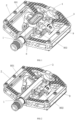
- disassembling the traditional integrated fixed hook structure into two parts and combining with the frame type pedal body reduce the gap on the pedal that can be attached to the mud, make the pedal structure simpler and clearer, and make the components to be relatively independent, so that the mud is not easily attached to the pedal.
- a pedal including a pedal shaft and a pedal body which is rotating connected with the spindle.
- the mentioned pedal body is provided with a fixing hook mechanism and an movable hook mechanism for fixing the anti-slip nail.
- the mentioned fixing hook mechanism includes a first fixing component and a second fixing component which is fixedly attached to the mentioned pedal body.
- the mentioned second fixing component is rotating connected with the mentioned movable hook mechanism.
- the mentioned first fixing component and movable hook mechanism clamp together to fix the anti-slip nail.
- the mentioned first fixing component include a U-shaped fixing part.
- the middle part of the mentioned U-shaped fixing part is provided with a locking part for locking the anti-slip nail.
- One side of the mentioned locking part which is near the pedal shaft is provided with a first fitting curved surface to fit the anti-slip nail.
- the lower side of the mentioned locking part can lock the anti-slip nail.
- the mentioned fixing part is provided with two symmetrical first supporting surfaces for supporting the anti-slip nail.
- the mentioned fixing part is also provided with a notch. Two first-connecting holes through the fixing part.
- the first bolt is passed through the mentioned first-connecting holes.
- the mentioned first bolt fixes the fixing part on the pedal body.
- the mentioned second fixing component includes installation part.
- the middle part of the mentioned installation part is provided with a second supporting surface for supporting the anti-slip nail.
- the side of the second supporting surface which is away from the pedal shaft is provided with two blocks fixed on the installation part.
- Both ends of the mentioned installation part are provided with an ear part extending downward.
- the mentioned ear part is perforated with a fixing hole.
- Both sides of the installation part are also perforated with two second-connecting holes.
- the mentioned second-connecting hole is provided with a second bolt.
- the mentioned second bolt is threaded to the pedal body and the second fixing component is fixed to the pedal body.
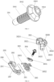
- the mentioned movable hook mechanism includes a connecting shaft passing through two fixing holes.
- the mentioned connecting shaft is provided with an movable cap.
- the mentioned movable cap includes two downward connecting parts and a limiting part.
- the mentioned connecting parts are provided with a through hole.
- the mentioned connecting shaft runs through the through hole.
- the side of the mentioned movable cap which is near the pedal shaft is provided with a contact surface capable of contacting the limit with the blocks.
- the middle or upper part of the mentioned movable cap is also provided with a second fitting curved surface which can be matched with the anti-slip nail.
- the lower side of the mentioned movable cap at the second fitting curved surface can lock the anti-slip nail.
- a mounting hole is run through the mentioned movable cap.
- An adjusting bolt is installed in the mentioned mounting hole.
- the mentioned adjusting bolt includes a head, a threaded part and an adjusting part.
- the mentioned adjusting part is provided with an adjusting hole in the end surface of the adjusting part.
- the mentioned adjusting part extends upward into the mounting hole.
- the mentioned threaded part through and threaded connected with the adjusting nut.
- a clamping part is arranged on one side of the adjusting nut which is away from the pedal shaft.
- a clamping hole is arranged through the limiting part to fit the clamping part. The mentioned clamping part extends into the clamping hole and restricts the rotation of the adjusting nut.
- the mentioned connecting shaft is also equipped with two springs which are positioned symmetrically between the connecting part.
- the mentioned springs include a first-end part and a second-end part.
- the mentioned first-end part abuts against the lower side of the blocks.
- the mentioned second-end abuts against the lower side of the adjusting nut.
- the anti-slip nail includes a first-locking surface for fitting the mentioned locking part, a first fitting end for fitting the first fitting curved surface, a second fitting end for fitting the second fitting curved surface, a second-locking surface for fitting the lower side of the movable cap.
- the lower side of the second fitting end is also arranged a guide surface on the anti-slip nail.
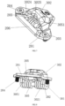
- the mentioned second fixing component 802 includes installation part 201.
- the middle part of the mentioned installation part 201 is provided with a second supporting surface 206 for supporting the anti-slip nail 4.
- the side of the second supporting surface 206 which is away from the pedal shaft 1 is provided with two blocks 205 fixed on the installation part 201.
- Both ends of the mentioned installation part 201 are provided with an ear part 202 extending downward.
- the mentioned ear part 202 is perforated with a fixing hole 207.
- Both sides of the installation part 201 are also perforated with two second-connecting holes 203.
- the mentioned second-connecting hole 203 is provided with a second bolt 204.
- the mentioned second bolt 204 is threaded to the pedal body 2 and the second fixing component 802 is fixed to the pedal body 2.
- the mentioned connecting shaft 301 is also equipped with two springs 305 which are positioned symmetrically between the connecting part 3021.
- the mentioned springs 305 include a first-end part 3051 and a second-end part 3052.
- the mentioned first-end part 3051 abuts against the lower side of the blocks 205.
- the mentioned second-end 3052 abut against the lower side of the adjusting nut 303.
- the pedal body 2 is provided with a first connecting arm 6 and a second connecting arm 7.
- the mentioned first connecting arm 6, the second connecting arm 7 and the pedal body 2 are provided with threaded holes 5.
- the mentioned two threaded holes 5 on one side of the first connecting arm 6 are matched with the first bolt 106.
- the mentioned two threaded holes 5 on one side of the second connecting arm 7 are matched with the second bolt 204.
Landscapes
- Engineering & Computer Science (AREA)
- Chemical & Material Sciences (AREA)
- Combustion & Propulsion (AREA)
- Transportation (AREA)
- Mechanical Engineering (AREA)
- Mechanical Control Devices (AREA)
Claims (4)
- Pédale de bicyclette, comprenant un arbre de pédale (1) et un corps de pédale (2) qui est relié de manière rotative à l'arbre de pédale (1), dans laquelle le corps de pédale (2) est pourvu d'un mécanisme de crochet de fixation (8) et d'un mécanisme de crochet mobile (9), pour maintenir un clou antidérapant (4), le mécanisme de crochet de fixation (8) comprend un premier composant de fixation (801) et un second composant de fixation (802), qui sont reliés de manière fixe au corps de pédale (2), le mécanisme de crochet mobile (9) est raccordé de manière rotative au second composant de fixation (802), dans laquelle le premier composant de fixation (801) et le mécanisme de crochet mobile (9) sont capables de se serrer l'un contre l'autre pour maintenir le clou antidérapant (4) ; dans laquelle le premier composant de fixation (801) comprend une partie de fixation en forme de U (107) ; une partie de verrouillage (101) pour verrouiller le clou antidérapant (4) est prévue dans une partie médiane de la partie de fixation en forme de U (107) ; un côté de la partie de verrouillage (101) qui est proche de l'arbre de pédale (1) est pourvu d'une première surface incurvée de réception (102) qui est conçue pour recevoir le clou antidérapant (4) ; un côté inférieur de la partie de verrouillage (101) est conçu pour verrouiller le clou antidérapant (4), la partie de fixation (107) est pourvue de deux premières surfaces de support symétriques (104) pour supporter le clou antidérapant (4), la partie de fixation (107) est également pourvue d'une encoche (103), deux premiers trous de liaison (105) sont prévus dans la partie de fixation (107), un premier boulon (106) passe à travers chacun des premiers trous de liaison (105), les premiers boulons (106) fixent la partie de fixation (107) sur le corps de pédale (2) ;dans laquelle le second composant de fixation (802) comprend une partie d'installation (201), la partie médiane de la partie d'installation (201) est pourvue d'une seconde surface de support (206) pour supporter le clou antidérapant (4), un côté de la seconde surface de support (206) qui est éloigné de l'arbre de pédale (1) est pourvu de deux blocs (205) installés de manière fixe sur la partie d'installation (201), deux extrémités de la partie d'installation (201) sont chacune pourvues d'une partie d'oreille (202) s'étendant vers le bas, chaque partie d'oreille (202) est perforée d'un trou de fixation (207), deux côtés de la partie d'installation (201) sont pourvus de deux seconds trous de liaison (203), un second boulon (204) est prévu dans chaque second trou de liaison (203), et les seconds boulons (204) sont reliés de manière filetée au corps de pédale (2) de façon à maintenir le second composant de fixation (802) contre le corps de pédale (2) ;dans laquelle le mécanisme de crochet mobile (9) comprend un arbre de liaison (301) traversant les deux trous de fixation (207), l'arbre de liaison (301) est pourvu d'un capuchon mobile (302), le capuchon mobile (302) comprend deux parties de liaison (3021) s'étendant vers le bas et une partie de limitation (3022), chacune des parties de liaison (3021) est pourvue d'un trou traversant (3027), l'arbre de liaison (301) s'étend à travers les trous traversants (3027), un côté du capuchon mobile (302) qui est proche de l'arbre de pédale (1) est pourvu d'une surface de contact (3024) qui est capable de venir en butée contre les blocs (205), une partie médiane ou supérieure du capuchon mobile (302) est pourvue d'une seconde surface incurvée de réception (3025) capable de venir en butée contre le clou antidérapant (4) et de recevoir celui-ci, un côté inférieur du capuchon mobile (302) au niveau de la seconde surface incurvée de réception (3025) est capable de verrouiller le clou antidérapant (4) ;dans laquelle un trou de réception (3026) est prévu dans le capuchon mobile (302), un boulon de réglage (304) est installé dans le trou de réception (3026), le boulon de réglage (304) comprend une tête (3042), une partie filetée (3041) et une partie de réglage (3043), la partie de réglage (3043) est pourvue d'un trou de réglage (3044) au niveau d'une surface d'extrémité de la partie de réglage (3043), la partie de réglage (3043) est capable de s'étendre vers le haut dans le trou de réception (3026), la partie filetée (3041) s'étend à travers un écrou de réglage (303) et est reliée de manière filetée à celui-ci, une partie de serrage (3031) est agencée sur un côté de l'écrou de réglage (303) qui est éloigné de l'arbre de pédale (1) ; un trou de serrage (3023), qui est conçu pour recevoir la partie de serrage (3031), est prévu dans la partie de limitation (3022) ; la partie de serrage (3031) s'étend dans le trou de serrage (3023), de manière à limiter une rotation de l'écrou de réglage (303) ;dans laquelle l'arbre de liaison (301) est gainé de deux ressorts (305) qui sont positionnés symétriquement entre les parties de liaison (3021), les ressorts (305) comprennent chacun une partie de première extrémité (3051) et une partie de seconde extrémité (3052), caractérisée en ce que chaque partie de première extrémité (3051) vient en butée contre le côté inférieur du bloc correspondant (205), chaque partie de seconde extrémité (3052) vient en butée contre le côté inférieur de l'écrou de réglage (303).
- Pédale de bicyclette selon la revendication 1, dans laquelle le clou antidérapant (4) comprend une surface de premier verrouillage (402) pour recevoir la partie de verrouillage (101), une première extrémité de réception (401) pour recevoir la première surface incurvée de réception (102), une seconde extrémité de réception (403) pour recevoir la seconde surface incurvée de réception (3025), une seconde surface de verrouillage (404) pour recevoir le côté inférieur du capuchon mobile (302),
dans laquelle un côté inférieur de la seconde extrémité de réception (403) est pourvu d'une surface de guidage (405) sur le clou antidérapant (4). - Pédale de bicyclette selon la revendication 1, dans laquelle le corps de pédale (2) est pourvu d'un premier bras de liaison (6) et d'un second bras de liaison (7) ; le premier bras de liaison (6), le second bras de liaison (7) et le corps de pédale (2) sont pourvus de trous filetés (5) ; deux desdits trous filetés (5) d'un côté du premier bras de liaison (6) correspondent aux premiers boulons (106), deux autres desdits trous filetés (5) d'un côté du second bras de liaison (7) correspondent aux seconds boulons (204).
- Pédale de bicyclette selon la revendication 1, dans laquelle des côtés supérieur et inférieur du corps de pédale (2) sont pourvus de lignes ondulées (3) pour augmenter une résistance.
Applications Claiming Priority (1)
| Application Number | Priority Date | Filing Date | Title |
|---|---|---|---|
| CN202321558049.XU CN220032136U (zh) | 2023-06-19 | 2023-06-19 | 一种脚踏板卡扣 |
Publications (3)
| Publication Number | Publication Date |
|---|---|
| EP4480802A1 EP4480802A1 (fr) | 2024-12-25 |
| EP4480802B1 true EP4480802B1 (fr) | 2025-06-25 |
| EP4480802C0 EP4480802C0 (fr) | 2025-06-25 |
Family
ID=87580106
Family Applications (1)
| Application Number | Title | Priority Date | Filing Date |
|---|---|---|---|
| EP23191566.1A Active EP4480802B1 (fr) | 2023-06-19 | 2023-08-16 | Pédale de bicyclette |
Country Status (3)
| Country | Link |
|---|---|
| US (1) | US12246794B2 (fr) |
| EP (1) | EP4480802B1 (fr) |
| CN (1) | CN220032136U (fr) |
Families Citing this family (4)
| Publication number | Priority date | Publication date | Assignee | Title |
|---|---|---|---|---|
| TWM644008U (zh) * | 2022-12-29 | 2023-07-21 | 維格工業股份有限公司 | 卡踏用踏板裝置 |
| USD1091396S1 (en) * | 2023-07-31 | 2025-09-02 | Fox Factory, Inc. | Pedal |
| USD1097896S1 (en) * | 2024-04-29 | 2025-10-14 | Ningbo Haojue Sports Equipment Co., Ltd | Clip of bicycle pedal |
| USD1138951S1 (en) * | 2024-12-20 | 2026-08-04 | D3 Innovation Inc. | Bicycle pedal |
Family Cites Families (14)
| Publication number | Priority date | Publication date | Assignee | Title |
|---|---|---|---|---|
| GB2266497B (en) * | 1992-04-28 | 1995-04-26 | Chen Chung I | Quick-release clipless pedal with two cleat engaging sides |
| TWM293881U (en) * | 2006-01-27 | 2006-07-11 | Jin-Lung Shie | Easily assembled bicycle pedal |
| CN202011462U (zh) * | 2011-02-09 | 2011-10-19 | 谢金龙 | 卡式踏板的模块式嵌扣机构及使用该嵌扣机构的卡式踏板 |
| CN202063236U (zh) * | 2011-04-15 | 2011-12-07 | 宁波嘉隆工业有限公司 | 一种自行车单、双面卡式脚踏 |
| US8661938B1 (en) * | 2012-10-18 | 2014-03-04 | Chung-I Chen | Pedal for a bicycle |
| CN104527901B (zh) * | 2014-12-17 | 2017-01-11 | 宁波巨隆机械股份有限公司 | 一种具有5°旋转角度的山地车双面卡扣脚踏 |
| US9957014B2 (en) * | 2015-10-08 | 2018-05-01 | Chin-Long Hsieh | Bicycle pedal |
| US10207769B1 (en) * | 2017-12-29 | 2019-02-19 | Chung-I Chen | Bicycle pedal |
| US10787226B1 (en) * | 2019-09-26 | 2020-09-29 | Scada International Co., Ltd. | Modularized clipless pedal for mountain bike |
| US10759490B1 (en) * | 2019-09-27 | 2020-09-01 | Scada International Co., Ltd. | Bicycle pedal with variable shaft mechanism |
| US11124265B1 (en) * | 2021-01-05 | 2021-09-21 | Ya-Hsin Liu | Clipless pedal |
| USD988939S1 (en) * | 2021-05-10 | 2023-06-13 | Cyclingdeal Usa, Inc. | Dual-sided bike pedal |
| USD973551S1 (en) * | 2021-05-12 | 2022-12-27 | Ning Bo Qi Ying Sports Equipment Co., Ltd. | Bicycle pedal |
| USD973552S1 (en) * | 2021-05-12 | 2022-12-27 | Ning Bo Qi Ying Sports Equipment Co., Ltd. | Bicycle pedal |
-
2023
- 2023-06-19 CN CN202321558049.XU patent/CN220032136U/zh active Active
- 2023-08-16 EP EP23191566.1A patent/EP4480802B1/fr active Active
- 2023-08-21 US US18/453,287 patent/US12246794B2/en active Active
Also Published As
| Publication number | Publication date |
|---|---|
| US20240417029A1 (en) | 2024-12-19 |
| EP4480802A1 (fr) | 2024-12-25 |
| CN220032136U (zh) | 2023-11-17 |
| US12246794B2 (en) | 2025-03-11 |
| EP4480802C0 (fr) | 2025-06-25 |
Similar Documents
| Publication | Publication Date | Title |
|---|---|---|
| EP4480802A1 (fr) | Pédale de bicyclette | |
| US7975810B2 (en) | Cam activated bicycle wheel brake | |
| US6745643B2 (en) | Side-mounted detachable pedal assembly | |
| US8267820B2 (en) | Bicycle chain tensioner | |
| US7571920B2 (en) | Bicycle front fork assembly | |
| WO2011014402A1 (fr) | Ensemble de fourche avant de bicyclette perfectionné | |
| US20110048165A1 (en) | Cage pedal | |
| US4553641A (en) | Hand-operated bicycle brake assembly | |
| USRE36970E (en) | Seat attachment apparatus | |
| CN209990752U (zh) | 一种膨胀固定头及使用该膨胀固定头的自行车 | |
| CN213292517U (zh) | 一种防转动手把扣具 | |
| CN216102629U (zh) | 中置电机的安装结构及助力自行车 | |
| CN2130758Y (zh) | 双向惯性助力制动装置 | |
| KR102405840B1 (ko) | 이륜차용 가방 거치대 | |
| CN212980441U (zh) | 应用于滑板车的折叠结构及滑板车 | |
| CN214184054U (zh) | 一种可调节尼龙扎带分离筛 | |
| CN223672681U (zh) | 一种座管夹及自行车 | |
| KR101170454B1 (ko) | 자동차용 스티어링 컬럼의 조정 장치 | |
| KR20160098728A (ko) | 탈부착 가능한 시트 완충장치 | |
| CN222836033U (zh) | 一种可延长的u型螺栓 | |
| CN210284460U (zh) | 一种具有防盗功能的自行车车座及自行车 | |
| CN214557888U (zh) | 一种采用凸轮扳手的曲线锯底板快夹结构 | |
| CN216268862U (zh) | 扶手管固定底座、扶手总成及客车 | |
| CN218751218U (zh) | 一种用于摩托车上的离合手柄结构 | |
| CN223628009U (zh) | 一种室内健身车踏板快脱结构 |
Legal Events
| Date | Code | Title | Description |
|---|---|---|---|
| PUAI | Public reference made under article 153(3) epc to a published international application that has entered the european phase |
Free format text: ORIGINAL CODE: 0009012 |
|
| STAA | Information on the status of an ep patent application or granted ep patent |
Free format text: STATUS: REQUEST FOR EXAMINATION WAS MADE |
|
| 17P | Request for examination filed |
Effective date: 20240528 |
|
| AK | Designated contracting states |
Kind code of ref document: A1 Designated state(s): AL AT BE BG CH CY CZ DE DK EE ES FI FR GB GR HR HU IE IS IT LI LT LU LV MC ME MK MT NL NO PL PT RO RS SE SI SK SM TR |
|
| RIC1 | Information provided on ipc code assigned before grant |
Ipc: B62M 3/08 20060101AFI20250305BHEP |
|
| GRAP | Despatch of communication of intention to grant a patent |
Free format text: ORIGINAL CODE: EPIDOSNIGR1 |
|
| STAA | Information on the status of an ep patent application or granted ep patent |
Free format text: STATUS: GRANT OF PATENT IS INTENDED |
|
| GRAS | Grant fee paid |
Free format text: ORIGINAL CODE: EPIDOSNIGR3 |
|
| INTG | Intention to grant announced |
Effective date: 20250416 |
|
| GRAA | (expected) grant |
Free format text: ORIGINAL CODE: 0009210 |
|
| STAA | Information on the status of an ep patent application or granted ep patent |
Free format text: STATUS: THE PATENT HAS BEEN GRANTED |
|
| AK | Designated contracting states |
Kind code of ref document: B1 Designated state(s): AL AT BE BG CH CY CZ DE DK EE ES FI FR GB GR HR HU IE IS IT LI LT LU LV MC ME MK MT NL NO PL PT RO RS SE SI SK SM TR |
|
| REG | Reference to a national code |
Ref country code: GB Ref legal event code: FG4D |
|
| REG | Reference to a national code |
Ref country code: CH Ref legal event code: EP |
|
| REG | Reference to a national code |
Ref country code: CH Ref legal event code: EP |
|
| REG | Reference to a national code |
Ref country code: IE Ref legal event code: FG4D |
|
| REG | Reference to a national code |
Ref country code: DE Ref legal event code: R096 Ref document number: 602023004250 Country of ref document: DE |
|
| U01 | Request for unitary effect filed |
Effective date: 20250702 |
|
| U07 | Unitary effect registered |
Designated state(s): AT BE BG DE DK EE FI FR IT LT LU LV MT NL PT RO SE SI Effective date: 20250709 |
|
| U20 | Renewal fee for the european patent with unitary effect paid |
Year of fee payment: 3 Effective date: 20250819 |
|
| PG25 | Lapsed in a contracting state [announced via postgrant information from national office to epo] |
Ref country code: NO Free format text: LAPSE BECAUSE OF FAILURE TO SUBMIT A TRANSLATION OF THE DESCRIPTION OR TO PAY THE FEE WITHIN THE PRESCRIBED TIME-LIMIT Effective date: 20250925 Ref country code: GR Free format text: LAPSE BECAUSE OF FAILURE TO SUBMIT A TRANSLATION OF THE DESCRIPTION OR TO PAY THE FEE WITHIN THE PRESCRIBED TIME-LIMIT Effective date: 20250926 |
|
| PG25 | Lapsed in a contracting state [announced via postgrant information from national office to epo] |
Ref country code: HR Free format text: LAPSE BECAUSE OF FAILURE TO SUBMIT A TRANSLATION OF THE DESCRIPTION OR TO PAY THE FEE WITHIN THE PRESCRIBED TIME-LIMIT Effective date: 20250625 |
|
| PG25 | Lapsed in a contracting state [announced via postgrant information from national office to epo] |
Ref country code: RS Free format text: LAPSE BECAUSE OF FAILURE TO SUBMIT A TRANSLATION OF THE DESCRIPTION OR TO PAY THE FEE WITHIN THE PRESCRIBED TIME-LIMIT Effective date: 20250925 |
|
| PG25 | Lapsed in a contracting state [announced via postgrant information from national office to epo] |
Ref country code: IS Free format text: LAPSE BECAUSE OF FAILURE TO SUBMIT A TRANSLATION OF THE DESCRIPTION OR TO PAY THE FEE WITHIN THE PRESCRIBED TIME-LIMIT Effective date: 20251025 |
|
| PG25 | Lapsed in a contracting state [announced via postgrant information from national office to epo] |
Ref country code: SM Free format text: LAPSE BECAUSE OF FAILURE TO SUBMIT A TRANSLATION OF THE DESCRIPTION OR TO PAY THE FEE WITHIN THE PRESCRIBED TIME-LIMIT Effective date: 20250625 |
|
| PG25 | Lapsed in a contracting state [announced via postgrant information from national office to epo] |
Ref country code: CZ Free format text: LAPSE BECAUSE OF FAILURE TO SUBMIT A TRANSLATION OF THE DESCRIPTION OR TO PAY THE FEE WITHIN THE PRESCRIBED TIME-LIMIT Effective date: 20250625 |
|
| PG25 | Lapsed in a contracting state [announced via postgrant information from national office to epo] |
Ref country code: PL Free format text: LAPSE BECAUSE OF FAILURE TO SUBMIT A TRANSLATION OF THE DESCRIPTION OR TO PAY THE FEE WITHIN THE PRESCRIBED TIME-LIMIT Effective date: 20250625 |
|
| PG25 | Lapsed in a contracting state [announced via postgrant information from national office to epo] |
Ref country code: SK Free format text: LAPSE BECAUSE OF FAILURE TO SUBMIT A TRANSLATION OF THE DESCRIPTION OR TO PAY THE FEE WITHIN THE PRESCRIBED TIME-LIMIT Effective date: 20250625 |
|
| PG25 | Lapsed in a contracting state [announced via postgrant information from national office to epo] |
Ref country code: ES Free format text: LAPSE BECAUSE OF FAILURE TO SUBMIT A TRANSLATION OF THE DESCRIPTION OR TO PAY THE FEE WITHIN THE PRESCRIBED TIME-LIMIT Effective date: 20250625 |
|
| PG25 | Lapsed in a contracting state [announced via postgrant information from national office to epo] |
Ref country code: MC Free format text: LAPSE BECAUSE OF FAILURE TO SUBMIT A TRANSLATION OF THE DESCRIPTION OR TO PAY THE FEE WITHIN THE PRESCRIBED TIME-LIMIT Effective date: 20250625 |
|
| PLBE | No opposition filed within time limit |
Free format text: ORIGINAL CODE: 0009261 |
|
| STAA | Information on the status of an ep patent application or granted ep patent |
Free format text: STATUS: NO OPPOSITION FILED WITHIN TIME LIMIT |
|
| REG | Reference to a national code |
Ref country code: CH Ref legal event code: L10 Free format text: ST27 STATUS EVENT CODE: U-0-0-L10-L00 (AS PROVIDED BY THE NATIONAL OFFICE) Effective date: 20260507 |
|
| 26N | No opposition filed |
Effective date: 20260326 |
|
| PG25 | Lapsed in a contracting state [announced via postgrant information from national office to epo] |
Ref country code: IE Free format text: LAPSE BECAUSE OF NON-PAYMENT OF DUE FEES Effective date: 20250816 |