EP4481184A1 - Flugzeuggondel mit mindestens einer schubumkehrvorrichtung mit mindestens einem längsspoiler zur aufnahme eines längsaktuators - Google Patents
Flugzeuggondel mit mindestens einer schubumkehrvorrichtung mit mindestens einem längsspoiler zur aufnahme eines längsaktuators Download PDFInfo
- Publication number
- EP4481184A1 EP4481184A1 EP24179337.1A EP24179337A EP4481184A1 EP 4481184 A1 EP4481184 A1 EP 4481184A1 EP 24179337 A EP24179337 A EP 24179337A EP 4481184 A1 EP4481184 A1 EP 4481184A1
- Authority
- EP
- European Patent Office
- Prior art keywords
- longitudinal
- deflector
- nacelle
- curvature
- lateral opening
- Prior art date
- Legal status (The legal status is an assumption and is not a legal conclusion. Google has not performed a legal analysis and makes no representation as to the accuracy of the status listed.)
- Pending
Links
Images


Classifications
-
- F—MECHANICAL ENGINEERING; LIGHTING; HEATING; WEAPONS; BLASTING
- F02—COMBUSTION ENGINES; HOT-GAS OR COMBUSTION-PRODUCT ENGINE PLANTS
- F02K—JET-PROPULSION PLANTS
- F02K1/00—Plants characterised by the form or arrangement of the jet pipe or nozzle; Jet pipes or nozzles peculiar thereto
- F02K1/54—Nozzles having means for reversing jet thrust
- F02K1/64—Reversing fan flow
- F02K1/70—Reversing fan flow using thrust reverser flaps or doors mounted on the fan housing
- F02K1/72—Reversing fan flow using thrust reverser flaps or doors mounted on the fan housing the aft end of the fan housing being movable to uncover openings in the fan housing for the reversed flow
-
- B—PERFORMING OPERATIONS; TRANSPORTING
- B64—AIRCRAFT; AVIATION; COSMONAUTICS
- B64C—AEROPLANES; HELICOPTERS
- B64C15/00—Attitude, flight direction, or altitude control by jet reaction
- B64C15/02—Attitude, flight direction, or altitude control by jet reaction the jets being propulsion jets
-
- B—PERFORMING OPERATIONS; TRANSPORTING
- B64—AIRCRAFT; AVIATION; COSMONAUTICS
- B64C—AEROPLANES; HELICOPTERS
- B64C3/00—Wings
- B64C3/32—Wings specially adapted for mounting power plant
-
- B—PERFORMING OPERATIONS; TRANSPORTING
- B64—AIRCRAFT; AVIATION; COSMONAUTICS
- B64D—EQUIPMENT FOR FITTING IN OR TO AIRCRAFT; FLIGHT SUITS; PARACHUTES; ARRANGEMENT OR MOUNTING OF POWER PLANTS OR PROPULSION TRANSMISSIONS IN AIRCRAFT
- B64D33/00—Arrangement in aircraft of power plant parts or auxiliaries not otherwise provided for
- B64D33/04—Arrangement in aircraft of power plant parts or auxiliaries not otherwise provided for of exhaust outlets or jet pipes
-
- F—MECHANICAL ENGINEERING; LIGHTING; HEATING; WEAPONS; BLASTING
- F02—COMBUSTION ENGINES; HOT-GAS OR COMBUSTION-PRODUCT ENGINE PLANTS
- F02K—JET-PROPULSION PLANTS
- F02K1/00—Plants characterised by the form or arrangement of the jet pipe or nozzle; Jet pipes or nozzles peculiar thereto
- F02K1/54—Nozzles having means for reversing jet thrust
- F02K1/76—Control or regulation of thrust reversers
- F02K1/763—Control or regulation of thrust reversers with actuating systems or actuating devices; Arrangement of actuators for thrust reversers
-
- F—MECHANICAL ENGINEERING; LIGHTING; HEATING; WEAPONS; BLASTING
- F05—INDEXING SCHEMES RELATING TO ENGINES OR PUMPS IN VARIOUS SUBCLASSES OF CLASSES F01-F04
- F05D—INDEXING SCHEME FOR ASPECTS RELATING TO NON-POSITIVE-DISPLACEMENT MACHINES OR ENGINES, GAS-TURBINES OR JET-PROPULSION PLANTS
- F05D2240/00—Components
- F05D2240/10—Stators
- F05D2240/12—Fluid guiding means, e.g. vanes
- F05D2240/129—Cascades, i.e. assemblies of similar profiles acting in parallel
-
- F—MECHANICAL ENGINEERING; LIGHTING; HEATING; WEAPONS; BLASTING
- F05—INDEXING SCHEMES RELATING TO ENGINES OR PUMPS IN VARIOUS SUBCLASSES OF CLASSES F01-F04
- F05D—INDEXING SCHEME FOR ASPECTS RELATING TO NON-POSITIVE-DISPLACEMENT MACHINES OR ENGINES, GAS-TURBINES OR JET-PROPULSION PLANTS
- F05D2240/00—Components
- F05D2240/10—Stators
- F05D2240/14—Casings or housings protecting or supporting assemblies within
-
- F—MECHANICAL ENGINEERING; LIGHTING; HEATING; WEAPONS; BLASTING
- F05—INDEXING SCHEMES RELATING TO ENGINES OR PUMPS IN VARIOUS SUBCLASSES OF CLASSES F01-F04
- F05D—INDEXING SCHEME FOR ASPECTS RELATING TO NON-POSITIVE-DISPLACEMENT MACHINES OR ENGINES, GAS-TURBINES OR JET-PROPULSION PLANTS
- F05D2250/00—Geometry
- F05D2250/20—Three-dimensional
- F05D2250/29—Three-dimensional machined; miscellaneous
- F05D2250/291—Three-dimensional machined; miscellaneous hollowed
-
- F—MECHANICAL ENGINEERING; LIGHTING; HEATING; WEAPONS; BLASTING
- F05—INDEXING SCHEMES RELATING TO ENGINES OR PUMPS IN VARIOUS SUBCLASSES OF CLASSES F01-F04
- F05D—INDEXING SCHEME FOR ASPECTS RELATING TO NON-POSITIVE-DISPLACEMENT MACHINES OR ENGINES, GAS-TURBINES OR JET-PROPULSION PLANTS
- F05D2250/00—Geometry
- F05D2250/30—Arrangement of components
- F05D2250/31—Arrangement of components according to the direction of their main axis or their axis of rotation
- F05D2250/311—Arrangement of components according to the direction of their main axis or their axis of rotation the axes being in line
-
- F—MECHANICAL ENGINEERING; LIGHTING; HEATING; WEAPONS; BLASTING
- F05—INDEXING SCHEMES RELATING TO ENGINES OR PUMPS IN VARIOUS SUBCLASSES OF CLASSES F01-F04
- F05D—INDEXING SCHEME FOR ASPECTS RELATING TO NON-POSITIVE-DISPLACEMENT MACHINES OR ENGINES, GAS-TURBINES OR JET-PROPULSION PLANTS
- F05D2250/00—Geometry
- F05D2250/70—Shape
- F05D2250/71—Shape curved
-
- F—MECHANICAL ENGINEERING; LIGHTING; HEATING; WEAPONS; BLASTING
- F05—INDEXING SCHEMES RELATING TO ENGINES OR PUMPS IN VARIOUS SUBCLASSES OF CLASSES F01-F04
- F05D—INDEXING SCHEME FOR ASPECTS RELATING TO NON-POSITIVE-DISPLACEMENT MACHINES OR ENGINES, GAS-TURBINES OR JET-PROPULSION PLANTS
- F05D2250/00—Geometry
- F05D2250/70—Shape
- F05D2250/75—Shape given by its similarity to a letter, e.g. T-shaped
Definitions
- the present application relates to an aircraft nacelle equipped with at least one thrust reverser device comprising a longitudinal deflector configured to house a longitudinal actuator as well as to an aircraft comprising at least one aircraft propulsion assembly comprising such a nacelle.
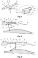
- an aircraft 10 comprises several propulsion units 12 positioned under each of the wings 14 of the aircraft 10 and connected to the latter by masts 16.
- Each propulsion unit 12 comprises a motorization 18 positioned inside a nacelle 20.
- the motorization 18 comprises a fan which has an axis of rotation A18.
- a longitudinal direction is parallel to the axis of rotation A18.
- a longitudinal plane is a plane containing the axis of rotation A18 and a transverse plane is a plane perpendicular to the axis of rotation A18.
- the concepts front/upstream and rear/downstream refer to the direction of flow of an air flow in the nacelle 20, the latter flowing from front (upstream) to rear (downstream).
- the nacelle 20 has an approximately tubular shape and delimits with the motorization 18 an annular duct 22 in which a secondary air flow flows.
- the nacelle 20 comprises an upstream part 24 as well as a downstream part 26 which extends to a trailing edge 28.
- the nacelle 20 comprises a thrust reverser device 30 positioned at the downstream portion 26 and configured to occupy an activated state in which it diverts at least a portion of the secondary air flow circulating in the annular duct 22 towards the outside and upstream of the nacelle 20 as well as an inactivated state in which it does not divert the secondary air flow circulating in the annular duct 22.
- the thrust reverser device 30 comprises at least one lateral opening 32 (visible in the figure 3 ) passing through the nacelle 20.
- the downstream part 26 of the nacelle 20 is movable between a first position, corresponding to the inactivated state of the thrust reverser device 30, in which the downstream part 26 is in contact with the upstream part 24 (as shown in the figure 2 ) and a second position, corresponding to the activated state of the thrust reverser device 30, in which the downstream part 26 is spaced from the upstream part 24 so as to generate the lateral opening 32 (as illustrated in the figure 3 ).
- the thrust reverser device 30 comprises several longitudinal actuators 34 connecting the upstream and downstream parts 24, 26, distributed around the circumference of the nacelle and configured to move the downstream part 26 back and forth or vice versa relative to the upstream part 24.
- the thrust reverser device 30 comprises a deflection system 36 configured to occupy a retracted position (visible in the figure 2 ), when the thrust reverser device 30 is in the inactivated state, in which the deflection system 36 does not interfere with the secondary airflow as well as a deployed position (visible on the figure 3 ), when the thrust reverser device 30 is in the activated state, in which the deflection system 36 interferes with the secondary air flow and directs it towards the lateral opening 32.
- the thrust reverser device 30 also comprises an orientation system 38 configured to orient the air flow deflected by the deflection system 36 towards the outside and upstream of the nacelle.
- the downstream part 26 comprises a cavity 40, open towards the upstream part 24, configured to house the orientation system 38 and the longitudinal actuators 34. This cavity 40 is delimited by interior and exterior walls 26.1, 26.2 spaced apart towards the upstream part 24 and connected at the trailing edge 28.
- the orientation system 38 comprises several blade grids 42, called cascades and positioned at the lateral opening 32, which each comprise first walls positioned in approximately longitudinal planes as well as second walls positioned in approximately transverse planes.
- the second walls have a blade shape to deflect the air flow exiting the lateral opening 32 upstream.
- the present invention aims to remedy all or part of the aforementioned drawbacks.
- each longitudinal deflector is connected to each transverse deflector.
- each transverse deflector comprises, for each longitudinal actuator passing through it, a cutout following the profile of the longitudinal deflector in which the longitudinal actuator is housed.
- each longitudinal deflector comprises first and second walls, each of the first and second walls having an inner edge and an outer edge further from the deflection system than the inner edge, the inner edges of the first and second walls being joined so as to form the leading edge, the outer edges being spaced apart.
- the longitudinal deflector comprises a third wall connecting the outer edges of the first and second walls.
- the first wall has a first portion extending from the inner edge and having a first radius of curvature and a second portion extending from the outer edge to the first portion and having a second radius of curvature.
- the second wall comprises a third portion extending from the inner edge and having a third radius of curvature and a fourth portion extending from the outer edge to the third portion and having a fourth radius of curvature.
- the third and fourth radii of curvature are equal and/or the second and fourth radii of curvature are equal and/or the first radius of curvature is significantly less than the third radius of curvature.
- the orientation system comprises several transverse deflectors each having inner and outer edges.
- the inner edges of the first and second walls of each longitudinal deflector are located at at least one of the inner edges of the transverse deflectors.
- the outer edges of the first and second walls of each longitudinal deflector are located at the outer edge of at least one of the transverse deflectors.
- the first and second walls have geometries determined according to a desired orientation for the air flow exiting the side opening.
- each longitudinal deflector extends between first and second ends, its aerodynamic profile varying between the first and second ends.
- the invention also relates to an aircraft comprising at least one nacelle according to one of the preceding characteristics.
- a propulsion assembly 50 comprises a motorization 52 positioned inside a nacelle 54.
- the latter has an approximately tubular shape and delimits with the motorization 52 an annular duct 56 in which a secondary air flow flows.
- the nacelle 54 comprises an upstream part 54.1 and a downstream part 54.2 which has a trailing edge 58.
- the nacelle 54 has an outer surface F54.
- an aircraft comprises at least one such propulsion assembly.
- the nacelle 54 is tubular and extends between upstream and downstream ends.
- the nacelle 54 is configured to channel an air flow 60 in a longitudinal direction, from the upstream end to the downstream end.
- the nacelle 54 comprises at least one thrust reversal device 62 positioned at the downstream portion 54.2 and configured to occupy an activated state (visible in the figures 5 And 7 ) in which it diverts at least part of the air flow 60 circulating in the annular duct 56 towards the outside and the upstream end of the nacelle 54 as well as an inactivated state (visible on the figure 6 ) in which it does not deflect the air flow 60 circulating in the annular duct 56.
- an activated state visible in the figures 5 And 7
- an inactivated state visible on the figure 6
- the thrust reverser device 62 comprises at least one lateral opening 64, passing through the nacelle 54 and distant from the upstream and downstream ends of the nacelle 54, configured to communicate the annular duct 56 and the exterior of the nacelle 54, in particular its exterior surface F54, as well as at least one mobile part 66 configured to occupy a first position, corresponding to the inactivated state of the thrust reverser device 62 (visible in the figure 6 ) in which the movable part 66 closes the lateral opening 64 and a second position, corresponding to the activated state of the thrust reversal device 62 (visible on the figures 5 And 7 ) in which the movable part 66 at least partially clears the lateral opening 64.
- This lateral opening 64 is delimited by upper and lower edges.
- the nacelle 54 comprises two lateral openings 64 substantially symmetrical with respect to a vertical longitudinal plane passing through the axis of the motorization.
- the downstream part 54.2 is a movable O-shaped tubular hood, forming the movable part 66, which translates in the longitudinal direction between a closed position (visible on the figure 6 ) in which the downstream part 54.2 is in contact with the upstream part 54.1, when the thrust reverser device 62 is in the inactivated state, and an open position (visible on the figures 5 And 7 ) in which the downstream portion 54.2 is spaced from the upstream portion 54.1 so as to generate the lateral opening(s) 64 between the upstream and downstream portions 54.1, 54.2 when the thrust reversal device 62 is in the activated state.
- the downstream part 54.2 comprises an inner wall 68.1 and an outer wall 68.2 connected at the trailing edge 58, the inner and outer walls 68.1, 68.2 delimiting between them a cavity 70 open in the direction of the upstream part 54.1.
- the invention is not limited to this configuration for the mobile part 66.
- the thrust reverser device 62 comprises at least one deflection system 72 configured to occupy a retracted position (visible in the figure 6 ), when the thrust reverser device 62 is in the inactivated state, in which the deflection system 72 does not interfere with the airflow 60 channeled by the nacelle 54 as well as a deployed position (visible on the figure 7 ), when the thrust reverser device 62 is in the activated state, in which the deflection system 72 is deployed in the annular duct 56, interferes with the air flow 60 and directs it in radial directions (perpendicular to the longitudinal direction) towards the lateral opening 64.
- the deflection system 72 comprises at least one panel 72.1 as well as, for each panel 72.1, at least one articulation 72.2 connecting the panel 72.1 to the nacelle 54 and at least one connecting rod 72.3 connecting the panel 72.1 to the motorization 52.
- the invention is not limited to this embodiment for the deflection system 72.
- each panel could be connected to the motorization 52 by an articulation.
- the thrust reverser device 62 also comprises at least one orientation system 74 configured to orient at least a portion of the air flow 60 deflected by the deflection system 72 and exiting via the lateral opening 64.
- the orientation system 74 is positioned at the lateral opening 64.
- the orientation system 74 and the cavity 70 are configured such that in the inactivated state, the orientation system 74 is positioned in the cavity 70.
- the orientation system 74 comprises at least one transverse deflector 76, positioned approximately in a transverse plane, which extends between first and second ends 76.1, 76.2.
- Each transverse deflector 76 has curved inner and outer edges 76.3, 76.4, substantially in an arc of a circle, connecting the first and second ends 76.1, 76.2, the inner edge 76.3 being closer to the deflection system 72 than the outer edge 76.4.
- the inner and outer edges 76.3, 76.4 have curvatures adapted to those of the inner and outer walls 68.1, 68.2 of the downstream part 54.2 of the nacelle 54 so that the orientation system 74 can be housed in the cavity 70 when the thrust reversal device 62 is in the inactivated state.
- Each transverse deflector 76 is configured to direct, in the radial directions and towards the upstream end, the air flow deflected by the deflection system 72 and exiting from the lateral opening 64.
- each transverse deflector 76 comprises a blade, in the form of a crown portion, which has a concave curvature in longitudinal planes (the center of the radius of curvature being offset upstream relative to the transverse deflector 76).
- each transverse deflector 76 has a constant width (distance separating the inner and outer edges 76.3, 76.4) and curvature between its first and second ends 76.1, 76.2.
- the air flow exiting the nacelle 54 is substantially constant around the periphery of the nacelle 54.
- the transverse deflectors 76 have different widths that decrease from upstream to downstream, as illustrated in FIG. figure 11 .
- transverse deflectors 76 and their shape are determined so as to obtain the same aerodynamic function as the cascades of the prior art, namely a flow rate sufficient to avoid operating problems with the 52 motor blower and to provide effective counter-thrust.
- the orientation system 74 comprises at least one support 78, integral with the nacelle 54, to which each transverse deflector 76 is connected.
- the support 78 comprises first and second uprights 80.1, 80.2, parallel to each other and to the longitudinal direction, positioned above and below the lateral opening 64, the first end 76.1 of each transverse deflector 76 being connected to the first upright 80.1, the second end 76.2 of each transverse deflector 76 being connected to the second upright 80.2.
- the first and second ends 76.1, 76.2 of each transverse deflector 76 are respectively connected to the support 78 at the upper and lower edges of the lateral opening 64.
- the support 78 comprises an upstream crosspiece 82, oriented in a direction parallel to a transverse plane and positioned upstream of the lateral opening 64, to which the first and second uprights 80.1, 80.2 are connected.
- the upstream crosspiece 82 has a curvature substantially identical to that of the nacelle 54.
- the upstream crosspiece 82 is integral with the upstream part 54.1 of the nacelle 54 or integrated therein.
- the support 78 comprises a downstream crosspiece 84 oriented in a direction parallel to a transverse plane and positioned downstream of the lateral opening 64.
- the downstream crosspiece 84 has a curvature substantially identical to that of the nacelle 54.
- the upstream and downstream crosspieces 82, 84 are parallel to each other and connected by the first and second uprights 80.1, 80.2.
- the upstream and downstream crosspieces 82, 84 as well as the first and second uprights 80.1, 80.2 form a frame delimiting the lateral opening 64.
- the thrust reverser device 62 comprises at least one longitudinal actuator 86, passing through the lateral opening 64, configured to move the movable part 66 and occupy a retracted state, corresponding to the inactivated state of the thrust reverser device 62, in which the movable part 66 closes the lateral opening 64 as well as a deployed state, corresponding to the activated state of the thrust reverser device 62, in which the movable part 66 at least partially clears the lateral opening 64.
- Each longitudinal actuator 86 is oriented in a direction substantially parallel to the longitudinal direction.
- each longitudinal actuator 86 is a cylinder and connects the upstream and downstream parts 54.1, 54.2.
- the thrust reverser device 62 comprises several longitudinal actuators 86, for example four longitudinal actuators 86, distributed over the circumference of the nacelle 54 and positioned symmetrically relative to the vertical longitudinal plane.
- Each longitudinal actuator 86 interferes with the transverse deflectors 76 of the orientation system 74.
- Each transverse deflector 76 comprises, for each longitudinal actuator 86 passing through it, a cutout 88 (visible in the figure 12 ).
- the orientation system 74 comprises, for each longitudinal actuator 86, a hollow longitudinal deflector 90, configured to house the longitudinal actuator 86, comprising an aerodynamic profile which has a leading edge 92 oriented towards the deflection system 72.
- This longitudinal deflector 90 flares out as it moves away from the deflection system 72.
- each longitudinal deflector 90 passes through the entire lateral opening 64 and has a first end 90.1 connected to the upstream crosspiece 82 as well as a second end 90.2 connected to the downstream crosspiece 84.
- each longitudinal deflector 90 comprises first and second walls 94, 96 forming a V in a transverse plane.
- Each of the first and second walls 94, 96 comprises an inner edge 94.1, 96.1 and an outer edge 94.2, 96.2 opposite the inner edge 94.1, 96.1, further from the deflection system 72 than the inner edge 94.1, 96.1, the inner edges 94.1, 96.1 of the first and second walls 94, 96 being contiguous so as to form the leading edge 92, the outer edges 94.2, 96.2 being spaced apart so that the first and second walls 94, 96 form a housing 98 configured to house a longitudinal actuator 86.
- each longitudinal deflector 90 is located at at least one of the inner edges 76.3 of the transverse deflectors 76.
- the outer edges 94.2, 96.2 of the first and second walls 94, 96 of each longitudinal deflector 90 are located at the outer edge 76.4 of at least one of the transverse deflectors 76.
- the longitudinal deflector 90 comprises a third wall 100 connecting the outer edges 94.2, 96.2 of the first and second walls so as to form a tubular longitudinal deflector 90.
- each longitudinal deflector 90 is connected to each transverse deflector 76. Connecting the longitudinal deflectors 90 to the transverse deflectors 76 helps to stiffen the latter. According to one configuration, the cutout 88 of each transverse deflector 76 follows the profile of the longitudinal deflector 90.
- the longitudinal deflector 90 has a constant cross-section between its first and second ends 90.1, 90.2. According to another embodiment, the longitudinal deflector 90 has a non-constant cross-section that varies between its first and second ends 90.1, 90.2, the cross-section varying depending on the desired orientation for the air flow exiting the lateral opening 64. According to one embodiment, the longitudinal deflector 90 has a symmetrical cross-section relative to a longitudinal plane, as illustrated in FIG. figure 8 . According to another embodiment, the longitudinal deflector has an asymmetrical cross section. For example, one of the first and second walls 94, 96 has a convex profile and the other a profile comprising a convex portion and a concave portion.
- first and second walls 94, 96 are flat. According to another embodiment, at least one of the first and second walls 94, 96 has a curved profile.
- the first and second walls 94, 96 may have geometries determined as a function of the desired orientation for the air flow exiting the lateral opening 64.
- the longitudinal deflector 90 has an aerodynamic profile which varies between the first and second ends 90.1, 90.2 as a function of the desired orientation for the air flow exiting the lateral opening 64.
- the first wall 94 has a first portion P1 extending from the inner edge 94.1 and having a first radius of curvature and a second portion P2 extending from the outer edge 94.2 to the first portion P1 and having a second radius of curvature.
- the second wall 96 comprises a third portion P3 extending from the inner edge 96.1 and having a third radius of curvature and a fourth portion P4 extending from the outer edge 96.2 to the third portion P3 and having a fourth radius of curvature.
- the third and fourth radii of curvature may be equal.
- the second and fourth radii of curvature may be equal.
- the first radius of curvature is significantly less than the third radius of curvature.
- the invention is not limited to this geometry for the longitudinal deflectors 90.
Landscapes
- Engineering & Computer Science (AREA)
- Mechanical Engineering (AREA)
- Chemical & Material Sciences (AREA)
- Combustion & Propulsion (AREA)
- General Engineering & Computer Science (AREA)
- Aviation & Aerospace Engineering (AREA)
- Wind Motors (AREA)
Applications Claiming Priority (1)
| Application Number | Priority Date | Filing Date | Title |
|---|---|---|---|
| FR2306154 | 2023-06-16 |
Publications (1)
| Publication Number | Publication Date |
|---|---|
| EP4481184A1 true EP4481184A1 (de) | 2024-12-25 |
Family
ID=88147018
Family Applications (1)
| Application Number | Title | Priority Date | Filing Date |
|---|---|---|---|
| EP24179337.1A Pending EP4481184A1 (de) | 2023-06-16 | 2024-05-31 | Flugzeuggondel mit mindestens einer schubumkehrvorrichtung mit mindestens einem längsspoiler zur aufnahme eines längsaktuators |
Country Status (3)
| Country | Link |
|---|---|
| US (1) | US12404820B2 (de) |
| EP (1) | EP4481184A1 (de) |
| CN (1) | CN119142514A (de) |
Citations (6)
| Publication number | Priority date | Publication date | Assignee | Title |
|---|---|---|---|---|
| FR1092654A (fr) * | 1952-11-25 | 1955-04-26 | Rolls Royce | Perfectionnements aux unités et installations de propulsion à réaction d'aérodynes |
| US2798362A (en) * | 1954-03-01 | 1957-07-09 | Armstrong Siddeley Motors Ltd | Means for slowing down an aircraft, particularly during landing, when powered by a turbo-jet |
| FR2358555A1 (fr) * | 1976-07-13 | 1978-02-10 | Short Brothers & Harland Ltd | Moteur a turbine a gaz a inversion de poussee |
| EP0109219A2 (de) * | 1982-11-12 | 1984-05-23 | LUCAS INDUSTRIES public limited company | Schubumlenkvorrichtung für einen Gasturbinenmotor |
| US20150308376A1 (en) * | 2014-04-25 | 2015-10-29 | Rohr, Inc. | Ladder cascade torque box |
| US11499503B1 (en) * | 2021-08-23 | 2022-11-15 | Honeywell International Inc. | Translating cowl thrust reverser system with efflux management |
Family Cites Families (3)
| Publication number | Priority date | Publication date | Assignee | Title |
|---|---|---|---|---|
| US9771894B2 (en) * | 2013-10-07 | 2017-09-26 | Rohr, Inc. | Radially connected cascade grids |
| FR3075760B1 (fr) * | 2017-12-21 | 2020-01-31 | Safran Nacelles | Nacelle de moteur d’aeronef |
| FR3126452B1 (fr) * | 2021-08-25 | 2024-11-01 | Safran Nacelles | Inverseur à grilles mobiles pour ensemble propulsif d’aéronef, comprenant un système pour limiter le flambage d’un actionneur de l’inverseur |
-
2024
- 2024-05-31 EP EP24179337.1A patent/EP4481184A1/de active Pending
- 2024-06-13 CN CN202410759099.7A patent/CN119142514A/zh active Pending
- 2024-06-13 US US18/742,458 patent/US12404820B2/en active Active
Patent Citations (6)
| Publication number | Priority date | Publication date | Assignee | Title |
|---|---|---|---|---|
| FR1092654A (fr) * | 1952-11-25 | 1955-04-26 | Rolls Royce | Perfectionnements aux unités et installations de propulsion à réaction d'aérodynes |
| US2798362A (en) * | 1954-03-01 | 1957-07-09 | Armstrong Siddeley Motors Ltd | Means for slowing down an aircraft, particularly during landing, when powered by a turbo-jet |
| FR2358555A1 (fr) * | 1976-07-13 | 1978-02-10 | Short Brothers & Harland Ltd | Moteur a turbine a gaz a inversion de poussee |
| EP0109219A2 (de) * | 1982-11-12 | 1984-05-23 | LUCAS INDUSTRIES public limited company | Schubumlenkvorrichtung für einen Gasturbinenmotor |
| US20150308376A1 (en) * | 2014-04-25 | 2015-10-29 | Rohr, Inc. | Ladder cascade torque box |
| US11499503B1 (en) * | 2021-08-23 | 2022-11-15 | Honeywell International Inc. | Translating cowl thrust reverser system with efflux management |
Also Published As
| Publication number | Publication date |
|---|---|
| US12404820B2 (en) | 2025-09-02 |
| US20240418137A1 (en) | 2024-12-19 |
| CN119142514A (zh) | 2024-12-17 |
Similar Documents
| Publication | Publication Date | Title |
|---|---|---|
| EP2368032B1 (de) | Schubumkehrer für eine mantelstromtriebwerksgondel | |
| EP0848153A1 (de) | Schubumkehrvorrichtung für ein Strahltriebwerk mit Umlenkklappen und an der festen Trägerstruktur behalteten Leitflächen | |
| WO2011135216A1 (fr) | Inverseur a portes | |
| EP0806563B1 (de) | Klappen mit Leitflächen für eine Schubumkehrvorrichtung eines Bläsertriebwerkes | |
| EP0836000B1 (de) | Klappenschubumkehrvorrichtung mit geregeltem Leckstrom | |
| EP0828934B1 (de) | Schubumkehrvorrichtung mit zwei klappen | |
| EP0882881B1 (de) | Schubumkehrvorrichtung für ein Strahltriebwerk dessen Umkehrklappen mit optimal entfaltbaren Leitflächen versehen sind | |
| FR2757901A1 (fr) | Inverseur de poussee de turboreacteur a double flux a coquilles aval | |
| FR2698913A1 (fr) | Ensemble d'inversion de poussée à portes équipé d'un dispositif de contrôle de jet. | |
| CA2267550A1 (fr) | Inverseur de poussee de turboreacteur a portes formant ecopes associees a un capotage externe articule | |
| WO1998055754A1 (fr) | Structure d'ejection equipee d'un inverseur de poussee a deux portes arriere et a section de sortie plane | |
| EP0807753B1 (de) | Schubumkehrvorrichtung eines Strahltriebwerkes mit an der Vorseite der Klappen verbundenem Wandteil | |
| FR2766522A1 (fr) | Inverseur de poussee de turbosoufflante a obstacle a guidage axial lies au capot primaire | |
| EP0807752B1 (de) | Schubumkehrvorrichtung mit beweglichen Auskleidungen in den Klappen | |
| EP3495651B1 (de) | Gitter zur erzeugung einer umkehrströmung eines luftfahrzeug-turbotriebwerks | |
| EP4293215A1 (de) | Flugzeugtriebwerksgondel mit schubumkehrvorrichtung mit beweglicher auswurfstruktur | |
| EP4481184A1 (de) | Flugzeuggondel mit mindestens einer schubumkehrvorrichtung mit mindestens einem längsspoiler zur aufnahme eines längsaktuators | |
| FR2947868A1 (fr) | Nacelle d'aeronef incorporant un dispositif pour inverser la poussee | |
| EP4455472A1 (de) | Flugzeuggondel mit mindestens einer schubumkehrvorrichtung mit einem stromabwärtsablenkelement, flugzeug mit mindestens einer antriebsanordnung mit solch einer gondel | |
| EP4528093A1 (de) | Flugzeuggondel mit mindestens einer schubumkehrvorrichtung mit mindestens einem längsspoiler, flugzeug mit mindestens einer antriebsanordnung mit solch einer gondel | |
| EP4455473A1 (de) | Flugzeuggondel mit mindestens einer schubumkehrvorrichtung mit mindestens einem längsspoiler, flugzeug mit mindestens einer antriebsanordnung mit solch einer gondel | |
| FR3152042A1 (fr) | Nacelle d’aéronef équipée d’au moins une structure d’orientation de flux d’air comprenant des déflecteurs transversaux en partie logés dans des renforts longitudinaux | |
| EP4470920A1 (de) | Flugzeugantriebsanordnung mit mindestens einem aerodynamischen panel, die von mindestens einem radialen zwischenträger getragen wird, luftfahrzeug, das mindestens eine solche antriebsanordnung umfasst | |
| FR3149044A1 (fr) | Inverseur de poussee comprenant au moins une membrane déployable de déviation | |
| FR2507558A1 (fr) | Groupe moteur de sustentation et de propulsion d'un vehicule de transport a coussin d'air |
Legal Events
| Date | Code | Title | Description |
|---|---|---|---|
| PUAI | Public reference made under article 153(3) epc to a published international application that has entered the european phase |
Free format text: ORIGINAL CODE: 0009012 |
|
| STAA | Information on the status of an ep patent application or granted ep patent |
Free format text: STATUS: THE APPLICATION HAS BEEN PUBLISHED |
|
| AK | Designated contracting states |
Kind code of ref document: A1 Designated state(s): AL AT BE BG CH CY CZ DE DK EE ES FI FR GB GR HR HU IE IS IT LI LT LU LV MC ME MK MT NL NO PL PT RO RS SE SI SK SM TR |
|
| STAA | Information on the status of an ep patent application or granted ep patent |
Free format text: STATUS: REQUEST FOR EXAMINATION WAS MADE |
|
| 17P | Request for examination filed |
Effective date: 20250611 |