EP4481202A1 - Impeller for radial fan - Google Patents
Impeller for radial fan Download PDFInfo
- Publication number
- EP4481202A1 EP4481202A1 EP24178789.4A EP24178789A EP4481202A1 EP 4481202 A1 EP4481202 A1 EP 4481202A1 EP 24178789 A EP24178789 A EP 24178789A EP 4481202 A1 EP4481202 A1 EP 4481202A1
- Authority
- EP
- European Patent Office
- Prior art keywords
- bead
- impeller
- blade
- base plate
- cover plate
- Prior art date
- Legal status (The legal status is an assumption and is not a legal conclusion. Google has not performed a legal analysis and makes no representation as to the accuracy of the status listed.)
- Pending
Links
Images


Classifications
-
- F—MECHANICAL ENGINEERING; LIGHTING; HEATING; WEAPONS; BLASTING
- F04—POSITIVE - DISPLACEMENT MACHINES FOR LIQUIDS; PUMPS FOR LIQUIDS OR ELASTIC FLUIDS
- F04D—NON-POSITIVE-DISPLACEMENT PUMPS
- F04D29/00—Details, component parts, or accessories
- F04D29/26—Rotors specially for elastic fluids
- F04D29/28—Rotors specially for elastic fluids for centrifugal or helico-centrifugal pumps for radial-flow or helico-centrifugal pumps
- F04D29/281—Rotors specially for elastic fluids for centrifugal or helico-centrifugal pumps for radial-flow or helico-centrifugal pumps for fans or blowers
- F04D29/282—Rotors specially for elastic fluids for centrifugal or helico-centrifugal pumps for radial-flow or helico-centrifugal pumps for fans or blowers the leading edge of each vane being substantially parallel to the rotation axis
-
- F—MECHANICAL ENGINEERING; LIGHTING; HEATING; WEAPONS; BLASTING
- F04—POSITIVE - DISPLACEMENT MACHINES FOR LIQUIDS; PUMPS FOR LIQUIDS OR ELASTIC FLUIDS
- F04D—NON-POSITIVE-DISPLACEMENT PUMPS
- F04D29/00—Details, component parts, or accessories
- F04D29/26—Rotors specially for elastic fluids
- F04D29/28—Rotors specially for elastic fluids for centrifugal or helico-centrifugal pumps for radial-flow or helico-centrifugal pumps
- F04D29/281—Rotors specially for elastic fluids for centrifugal or helico-centrifugal pumps for radial-flow or helico-centrifugal pumps for fans or blowers
-
- F—MECHANICAL ENGINEERING; LIGHTING; HEATING; WEAPONS; BLASTING
- F04—POSITIVE - DISPLACEMENT MACHINES FOR LIQUIDS; PUMPS FOR LIQUIDS OR ELASTIC FLUIDS
- F04D—NON-POSITIVE-DISPLACEMENT PUMPS
- F04D17/00—Radial-flow pumps, e.g. centrifugal pumps; Helico-centrifugal pumps
- F04D17/08—Centrifugal pumps
- F04D17/16—Centrifugal pumps for displacing without appreciable compression
-
- F—MECHANICAL ENGINEERING; LIGHTING; HEATING; WEAPONS; BLASTING
- F04—POSITIVE - DISPLACEMENT MACHINES FOR LIQUIDS; PUMPS FOR LIQUIDS OR ELASTIC FLUIDS
- F04D—NON-POSITIVE-DISPLACEMENT PUMPS
- F04D29/00—Details, component parts, or accessories
- F04D29/18—Rotors
- F04D29/22—Rotors specially for centrifugal pumps
- F04D29/2205—Conventional flow pattern
- F04D29/2222—Construction and assembly
-
- F—MECHANICAL ENGINEERING; LIGHTING; HEATING; WEAPONS; BLASTING
- F04—POSITIVE - DISPLACEMENT MACHINES FOR LIQUIDS; PUMPS FOR LIQUIDS OR ELASTIC FLUIDS
- F04D—NON-POSITIVE-DISPLACEMENT PUMPS
- F04D29/00—Details, component parts, or accessories
- F04D29/26—Rotors specially for elastic fluids
- F04D29/28—Rotors specially for elastic fluids for centrifugal or helico-centrifugal pumps for radial-flow or helico-centrifugal pumps
- F04D29/30—Vanes
-
- F—MECHANICAL ENGINEERING; LIGHTING; HEATING; WEAPONS; BLASTING
- F04—POSITIVE - DISPLACEMENT MACHINES FOR LIQUIDS; PUMPS FOR LIQUIDS OR ELASTIC FLUIDS
- F04D—NON-POSITIVE-DISPLACEMENT PUMPS
- F04D29/00—Details, component parts, or accessories
- F04D29/60—Mounting; Assembling; Disassembling
- F04D29/62—Mounting; Assembling; Disassembling of radial or helico-centrifugal pumps
- F04D29/624—Mounting; Assembling; Disassembling of radial or helico-centrifugal pumps especially adapted for elastic fluid pumps
- F04D29/626—Mounting or removal of fans
-
- F—MECHANICAL ENGINEERING; LIGHTING; HEATING; WEAPONS; BLASTING
- F05—INDEXING SCHEMES RELATING TO ENGINES OR PUMPS IN VARIOUS SUBCLASSES OF CLASSES F01-F04
- F05D—INDEXING SCHEME FOR ASPECTS RELATING TO NON-POSITIVE-DISPLACEMENT MACHINES OR ENGINES, GAS-TURBINES OR JET-PROPULSION PLANTS
- F05D2240/00—Components
- F05D2240/20—Rotors
- F05D2240/30—Characteristics of rotor blades, i.e. of any element transforming dynamic fluid energy to or from rotational energy and being attached to a rotor
- F05D2240/307—Characteristics of rotor blades, i.e. of any element transforming dynamic fluid energy to or from rotational energy and being attached to a rotor related to the tip of a rotor blade
Definitions
- the present invention relates to the technical field of impellers for radial fans for conveying a gaseous fluid.
- Impellers for radial fans are already known to the expert from the state of the art.
- the document EP 2 846 046 A1 discloses, for example, a fan wheel for conveying a gaseous fluid with a plurality of blades which are arranged at a constant angular pitch in an annular volume around a rotation axis and which are each fixed to a support means with their axially opposite end regions.
- At least one blade has an edge region, in particular a frame-shaped peripheral region, and at least one inner region surrounded by the edge region, wherein between the edge region and the inner region at least one bead is formed along an at least L-shaped, preferably U-shaped, in particular peripheral curve and/or wherein the edge region is determined by a first blade surface and the inner region is determined by a second blade surface which is arranged and/or formed geometrically differently from the first blade surface.
- impellers of radial fans which comprise flat base disks and cover disks on which blades are attached.
- the disadvantage here is always that, for example, an increase in the speed stability is accompanied by a loss of the conveying effect of the impeller or an increase in the conveying effect negatively affects the speed stability.
- the technical object of the invention is therefore to propose an improvement in the speed stability while maintaining at least the same conveying effect of an impeller of a radial fan.
- the proposed designs can relate to all components of the impeller, for example made of metal, but also only to individual components of the impeller.
- the components of an impeller are understood to mean the cover plate, base plate and blades.
- the proposed designs can relate to all blades of an impeller, but also only to individual blades of an impeller. In other words, a design of only one of the aforementioned components can be advantageous, but a design of all components achieves the most advantages.
- a width of the bead is understood to mean a width in a plan view in the axial direction of the impeller.
- a height of the bead is to be understood as a positive or negative height in the axial direction, starting from the cover and/or base plate, of the impeller.
- an impeller of a radial fan for conveying a gaseous fluid comprising a base plate, a cover plate, wherein the cover plate is arranged at a distance from the base plate in the axial direction of the impeller, wherein the cover plate and/or the base plate have at least one embossed bead, in particular a plurality of embossed bead, a plurality of blades, wherein at least one blade is arranged between the cover plate and the base plate and is fastened in the region and in the course of at least one bead, wherein a surface course of the bead follows a surface course of the blade fastened to the bead, at least in an envelope, such that a conveying effect of the bead corresponds at least to a conveying effect of a blade area reduced due to the bead.
- an envelope can be understood as, for example, a contour or a surface that surrounds the object enclosed by it, such as the blade.
- it can be provided to emboss beads in the cover and/or base plate in the direction of the blades. The blade then sits on, at, or in these beads and is thereby shortened and adapted in shape, which means that the Leverage ratios can be improved and the transition between the blade and the cover and/or base disk can be made less stressed.
- the stresses that occur in the entire impeller during operation of the impeller can thus be reduced.
- stresses that are introduced from the blades into the cover and/or base disk can be advantageously reduced.
- the strength of the impeller can thus be increased and higher rotational speeds, or higher circumferential speeds, can thus be achieved.
- the blade is arranged on the bead, in particular on the bead, preferably in the bead.
- the bead is embossed along a contour of the blade, in particular along a contour of an edge region of the blade adjacent to the cover disk or the base disk.
- a height of the bead varies and in particular increases in the radial direction of the impeller.
- the height of the bead corresponds to a tenth part, in particular a fifteenth part, in particular a twentieth part, preferably at most a fiftieth part, of a distance between the base plate and the cover plate.
- a width of the bead varies and in particular increases in the radial direction of the impeller.
- the bead is interrupted in the radial direction of the impeller, in particular is only partially formed.
- the bead in particular a flank of the bead, is formed parallel or profiled to the blade, preferably to a contour of the blade.
- the shape of the bead can be parallel to the blade, but it can also have a profile shape, for example in an arrangement in the middle of the blade, which can have an additional beneficial effect on the stability and strength of the impeller.
- the bead has a pressure-side profile, in particular a pressure-side contour profile, which deviates from a suction-side profile of the bead, in particular a suction-side contour profile of the bead.
- This can also advantageously enable more flexible production to improve the stability and strength of the impeller.
- the bead in particular a bead outlet of the bead, has a, preferably partially, curvature-continuous transition into the base plate and/or into the cover plate.
- the blade is fastened by means of a welded and/or lashed and/or screwed and/or riveted and/or glued and/or caulked connection, wherein the fastening is arranged in particular on the pressure side and/or suction side of the blade.
- the fastening is designed in several parts, wherein either at least a first part of the fastening is formed between the blade and the base plate and at least a second part of the fastening is formed between the blade and the bead, or wherein at least a first part of the fastening is formed between the blade and the cover plate and at least a second part of the fastening is formed between the blade and the bead.
- the blade can be attached to the base plate or the cover plate or the bead with particular stability and a higher flexibility in production can thus be achieved.
- the blade is arranged between a pair of beads, wherein the pair of beads comprises a first and a second bead, wherein the first bead is arranged on the cover disk and the second bead is arranged on the base disk is formed, wherein in particular the first and/or the second bead are formed according to one of the preceding claims.
- a radial fan comprising a housing, a motor, in particular a control device, and an impeller for conveying a gaseous fluid, characterized in that the impeller is designed according to one of the preceding claims.
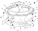
- FIG 1 is a perspective view of an impeller 1 of a radial fan for conveying a gaseous fluid, comprising a base plate 2, a cover plate 3, wherein the cover plate 3 is spaced from the base plate 2 in the axial direction of the impeller 1 and is arranged at a distance 4 between the base plate 2 and the cover plate 3, wherein the cover plate 3 and the base plate 2 have at least one embossed Bead 5, in particular a plurality of embossed beads 5, a plurality of blades 7, wherein at least one blade 7 is arranged between the cover disk 3 and the base disk 2 and is fastened in the region and in the course of at least one bead 5, wherein a surface course of the bead 5 follows a surface course of the blade fastened to the bead 5, at least in an envelope, such that a conveying effect of the bead 5 corresponds at least to a conveying effect of a blade surface 8 reduced due to the bead.
- the blade 7 can thereby advantageously be shortened and at the same time
- the blade 7 is arranged on the bead 5.
- the bead 5 is embossed along a contour of the blade 9, in particular along a contour of an edge region of the blade that is adjacent to the cover plate 3 or the base plate 2.
- the bead 5, in particular a bead outlet 6a of the bead 5 has a curvature-continuous transition into the base plate 2 and into the cover plate.
- a fastening 12 of the blade 7 is shown as an example formed by means of a welded connection, wherein the fastening 12 is shown arranged on the pressure side and suction side of the blade.
- the blade 5 is arranged between a pair of beads (not designated), wherein the pair of beads comprises a first bead 13 and a second bead 14, wherein the first bead 13 is formed on the cover disk 3 and the second bead 14 on the base disk 2.
- the pair of beads comprises a first bead 13 and a second bead 14, wherein the first bead 13 is formed on the cover disk 3 and the second bead 14 on the base disk 2.
- the fastening 12 is designed in several parts, with a first part of the fastening 16 of the blade 7 being designed between the blade 7 and the cover plate 3 and at least a second part of the fastening 17 being designed between the blade 7 and the bead 5.
- the stability of the blade 7 on the cover plate 3 can thus advantageously be improved.
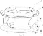
- FIG 2 is another perspective view of a wheel, analogous to Figure 1 , shown.
- a height 10 of the bead 5 varies in the radial direction of the impeller and increases towards the outside.
- Analogous to the Figures 1 and 2 is in Figure 3 shown how the height 10 of the bead 5 decreases towards the outside.
- the height of the bead 5 corresponds to a tenth, preferably an eighth, preferably a sixth part of the distance 4 between the base plate 2 and the cover plate 3. In this way, higher speeds and higher rotational speeds can be advantageously achieved with the same conveying capacity.
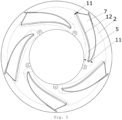
- Figure 4 is shown, analogous to the other figures, a top view of a base plate 2 with beads 5.
- a width 11 of the bead 5 varies in the radial direction of the impeller and decreases towards the outside. It is also shown that the bead 5 has a pressure-side profile, in particular a pressure-side contour profile, which deviates from a suction-side profile of the bead 5, in particular a suction-side contour profile of the bead 5.
- the bead 5 is parallel or profiled to the one in the Figures 1 to 3 illustrated blade 7 is formed.
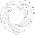
- FIG. 5 and 6 an axial top view of a base plate 2 with blades 7 arranged thereon by means of fastenings 12 is shown.
- the width 11 of the bead 5 takes up Figure 5 to the radially outer edge of the base plate 2, thus to the radially outer edge of the, for example, Figure 1 shown impeller 1.
- Figure 6 the embodiment analogous to Figure 5 in which the width 11 of the beads 5 decreases towards the edge, ie increases in the radial direction outwards.
Landscapes
- Engineering & Computer Science (AREA)
- Mechanical Engineering (AREA)
- General Engineering & Computer Science (AREA)
- Structures Of Non-Positive Displacement Pumps (AREA)
Abstract
Laufrad 1 eines Radiallüfters zur Förderung eines gasförmigen Fluids, das Laufrad 1 umfassend eine Bodenscheibe 2, eine Deckscheibe 3, wobei die Deckscheibe 3 zu der Bodenscheibe 2 in axialer Richtung 15 des Laufrades 1 beabstandet angeordnet ist, wobei die Deckscheibe 3 und/oder die Bodenscheibe 2 wenigstens eine eingeprägte Sicke 5, insbesondere eine Mehrzahl an eingeprägten Sicken 5 aufweisen, eine Mehrzahl an Schaufeln 7, wobei wenigstens eine Schaufel 7 zwischen der Deckscheibe 3 und der Bodenscheibe 2 angeordnet ist und im Bereich und im Verlauf wenigstens einer Sicke 5, befestigt ist, wobei ein Oberflächenverlauf der Sicke 5 einem Oberflächenverlauf der an der Sicke 5 befestigten Schaufel 7, zumindest in einer Einhüllenden, derart folgt, sodass eine Förderwirkung der Sicke 5 zumindest einer Förderwirkung einer auf Grund der Sicke 5 reduzierten Schaufelfläche 8 entspricht.Impeller 1 of a radial fan for conveying a gaseous fluid, the impeller 1 comprising a base disk 2, a cover disk 3, wherein the cover disk 3 is arranged at a distance from the base disk 2 in the axial direction 15 of the impeller 1, wherein the cover disk 3 and/or the base disk 2 have at least one embossed bead 5, in particular a plurality of embossed beads 5, a plurality of blades 7, wherein at least one blade 7 is arranged between the cover disk 3 and the base disk 2 and is fastened in the region and in the course of at least one bead 5, wherein a surface course of the bead 5 follows a surface course of the blade 7 fastened to the bead 5, at least in one envelope, such that a conveying effect of the bead 5 corresponds at least to a conveying effect of a blade area 8 reduced due to the bead 5.
Description
Die vorliegende Erfindung betrifft das technische Gebiet der Laufräder für Radiallüfter zur Förderung eines gasförmigen Fluids.The present invention relates to the technical field of impellers for radial fans for conveying a gaseous fluid.
Laufräder für Radiallüfter sind dem Fachmann bereits aus dem Stand der Technik bekannt.Impellers for radial fans are already known to the expert from the state of the art.
Das Dokument
Weiterhin sind Laufräder von Radiallüftern bekannt, die ebene Bodenscheiben und Deckenscheiben umfassen, auf denen Schaufeln befestigt sind.Furthermore, impellers of radial fans are known, which comprise flat base disks and cover disks on which blades are attached.
Nachteilig ist hierbei stets, dass beispielsweise eine Erhöhung der Drehzahlfestigkeit mit einem Verlust der Förderwirkung des Laufrades einhergeht oder eine Erhöhung der Förderwirkung, die Drehzahlfestigkeit negativ beeinflusst.The disadvantage here is always that, for example, an increase in the speed stability is accompanied by a loss of the conveying effect of the impeller or an increase in the conveying effect negatively affects the speed stability.
Technische Aufgabe der Erfindung ist es daher, eine Verbesserung der Drehzahlfestigkeit bei zumindest gleichbleibender Förderwirkung eines Laufrades eines Radiallüfters vorzuschlagen.The technical object of the invention is therefore to propose an improvement in the speed stability while maintaining at least the same conveying effect of an impeller of a radial fan.
Die technische Aufgabe wird durch einen Gegenstand mit den technischen Merkmalen nach dem unabhängigen Anspruch gelöst. Vorteilhafte Ausführungsformen sind Gegenstand der abhängigen Ansprüche, der Beschreibung und der Zeichnungen.The technical problem is solved by an object having the technical features according to the independent claim. Advantageous embodiments are the subject of the dependent claims, the description and the drawings.
Im Sinne der Erfindung ist vorgesehen, dass die vorgeschlagenen Ausgestaltungen sämtliche Bestandteile des, beispielsweise aus Metall gefertigten, Laufrades, aber auch nur einzelne Bestandteile des Laufrades betreffen können. Unter den Bestandteilen eines Laufrades sind im Sinne der Erfindung, Deckscheibe, Bodenscheibe, sowie Schaufeln zu verstehen. Außerdem ist im Sinne der Erfindung vorgesehen, dass die vorgeschlagenen Ausgestaltungen sämtliche Schaufeln eines Laufrades, aber auch nur einzelne Schaufeln eines Laufrades betreffen können. In anderen Worten kann eine Ausgestaltung nur eines der vorgenannten Bestandteile vorteilhaft sein, eine Ausgestaltung aller Bestandteile erzielt jedoch die meisten Vorteile.In the sense of the invention, it is provided that the proposed designs can relate to all components of the impeller, for example made of metal, but also only to individual components of the impeller. In the sense of the invention, the components of an impeller are understood to mean the cover plate, base plate and blades. In the sense of the invention, it is also provided that the proposed designs can relate to all blades of an impeller, but also only to individual blades of an impeller. In other words, a design of only one of the aforementioned components can be advantageous, but a design of all components achieves the most advantages.
Im Sinne der Erfindung ist unter einer Breite der Sicke eine Breite in einer Draufsicht in axialer Blickrichtung auf das Laufrad zu verstehen.For the purposes of the invention, a width of the bead is understood to mean a width in a plan view in the axial direction of the impeller.
Weiterhin ist im Sinne der Erfindung eine Höhe der Sicke als eine positive, oder negative Höhe in axialer Richtung, ausgehend von der Deck- und/oder Bodenscheibe, des Laufrades zu verstehen.Furthermore, in the sense of the invention, a height of the bead is to be understood as a positive or negative height in the axial direction, starting from the cover and/or base plate, of the impeller.
Gemäß einem Aspekt wird die technische Aufgabe der Erfindung gelöst, durch ein Laufrad eines Radiallüfters zur Förderung eines gasförmigen Fluids, das Laufrad umfassend eine Bodenscheibe, eine Deckscheibe, wobei die Deckscheibe zu der Bodenscheibe in axialer Richtung des Laufrades beabstandet angeordnet ist, wobei die Deckscheibe und/oder die Bodenscheibe wenigstens eine eingeprägte Sicke, insbesondere eine Mehrzahl an eingeprägten Sicken aufweisen, eine Mehrzahl an Schaufeln, wobei wenigstens eine Schaufel zwischen der Deckscheibe und der Bodenscheibe angeordnet ist und im Bereich und im Verlauf wenigstens einer Sicke, befestigt ist, wobei ein Oberflächenverlauf der Sicke einem Oberflächenverlauf der an der Sicke befestigten Schaufel, zumindest in einer Einhüllenden, derart folgt, sodass eine Förderwirkung der Sicke zumindest einer Förderwirkung einer auf Grund der Sicke reduzierten Schaufelfläche entspricht.According to one aspect, the technical object of the invention is achieved by an impeller of a radial fan for conveying a gaseous fluid, the impeller comprising a base plate, a cover plate, wherein the cover plate is arranged at a distance from the base plate in the axial direction of the impeller, wherein the cover plate and/or the base plate have at least one embossed bead, in particular a plurality of embossed bead, a plurality of blades, wherein at least one blade is arranged between the cover plate and the base plate and is fastened in the region and in the course of at least one bead, wherein a surface course of the bead follows a surface course of the blade fastened to the bead, at least in an envelope, such that a conveying effect of the bead corresponds at least to a conveying effect of a blade area reduced due to the bead.
Im Sinne der Erfindung kann unter einer Einhüllenden beispielsweise eine Kontur oder eine Oberfläche verstanden werden, die das sich von ihr umschlossene Objekt, wie beispielsweise die Schaufel, umgibt.In the sense of the invention, an envelope can be understood as, for example, a contour or a surface that surrounds the object enclosed by it, such as the blade.
Vorteilhaft kann hierdurch einerseits eine Verkürzung der Schaufel und gleichzeitig eine Versteifung der Bodenscheibe ermöglicht werden. Es kann beispielsweise vorgesehen sein, Sicken in der Deck- und/oder Bodenscheibe in Richtung der Schaufeln zu prägen. Die Schaufel sitzt sodann auf, oder an, oder in diesen Sicken und wird dadurch gekürzt und in der Form angepasst, wodurch im Betrieb des Laufrades auftretende Hebelverhältnisse verbessert werden können und der Übergang zwischen Schaufel und Deck- und/oder Bodenscheibe entschärft werden kann. Die im Betrieb des Laufrades auftretenden Spannungen im gesamten Laufrad können somit reduziert werden. Insbesondere können Spannungen, die von den Schaufeln in die Deck- und/oder Bodenscheibe eingeleitet werden, vorteilhaft reduziert werden. Die Festigkeit des Laufrades kann dadurch erhöht und höhere Drehzahlen, respektive höhere Umfangsgeschwindigkeiten, können somit erreicht werden.This can advantageously make it possible to shorten the blade and at the same time stiffen the base plate. For example, it can be provided to emboss beads in the cover and/or base plate in the direction of the blades. The blade then sits on, at, or in these beads and is thereby shortened and adapted in shape, which means that the Leverage ratios can be improved and the transition between the blade and the cover and/or base disk can be made less stressed. The stresses that occur in the entire impeller during operation of the impeller can thus be reduced. In particular, stresses that are introduced from the blades into the cover and/or base disk can be advantageously reduced. The strength of the impeller can thus be increased and higher rotational speeds, or higher circumferential speeds, can thus be achieved.
Zusätzlich können Kosten reduziert und eine höhere Flexibilität bei der Konstruktion eines Laufrades ermöglicht werden.In addition, costs can be reduced and greater flexibility in the design of a wheel can be achieved.
In einer technisch vorteilhaften Ausführungsform des Laufrades ist vorgesehen, dass die Schaufel auf der Sicke, insbesondere an der Sicke, bevorzugt in der Sicke angeordnet ist.In a technically advantageous embodiment of the impeller, it is provided that the blade is arranged on the bead, in particular on the bead, preferably in the bead.
Dies kann zusätzlich die Flexibilität bei der Herstellung eines Laufrades vergrößern.This can further increase the flexibility in the manufacture of a wheel.
In einer weiteren technisch vorteilhaften Ausführungsform des Laufrades ist vorgesehen, dass die Sicke entlang einer Kontur der Schaufel, insbesondere entlang einer Kontur eines an der Deckscheibe oder an der Bodenscheibe anliegenden Randbereichs der Schaufel, eingeprägt ist.In a further technically advantageous embodiment of the impeller, it is provided that the bead is embossed along a contour of the blade, in particular along a contour of an edge region of the blade adjacent to the cover disk or the base disk.
Vorteilhaft kann dieses zusätzlich die Stabilität und die Festigkeit des Laufrades verbessern.This can also advantageously improve the stability and strength of the wheel.
Außerdem ist in einer weiteren technisch vorteilhaften Ausführungsform des Laufrades vorgesehen, dass eine Höhe der Sicke in radialer Richtung des Laufrades variiert und insbesondere zunimmt.Furthermore, in a further technically advantageous embodiment of the impeller, it is provided that a height of the bead varies and in particular increases in the radial direction of the impeller.
Hierdurch können besondere Anforderungen beim Einsatz des Laufrades berücksichtigt werden und die Herstellung entsprechend angepasst werden, um zusätzlich eine Erhöhung der Festigkeit des Laufrades zu erreichen.This allows special requirements to be taken into account when using the impeller and the production to be adapted accordingly in order to additionally increase the strength of the impeller.
Darüber hinaus ist in einer weiteren technisch vorteilhaften Ausführungsform des Laufrades vorgesehen, dass die Höhe der Sicke einem zehnten Teil, insbesondere einem fünfzehnten Teil, insbesondere einem zwanzigsten Teil, bevorzugt höchstens einem fünfzigsten Teil, einer Distanz zwischen Bodenscheibe und Deckscheibe entspricht.Furthermore, in a further technically advantageous embodiment of the impeller, it is provided that the height of the bead corresponds to a tenth part, in particular a fifteenth part, in particular a twentieth part, preferably at most a fiftieth part, of a distance between the base plate and the cover plate.
Auch dies kann zusätzlich die Möglichkeiten zur Herstellung unter Berücksichtigung gegebener Anwendungserfordernisse vergrößern.This can also further increase the possibilities for manufacturing taking into account given application requirements.
Weiterhin ist in einer weiteren technisch vorteilhaften Ausführungsform des Laufrades vorgesehen, dass eine Breite der Sicke in radialer Richtung des Laufrades variiert und insbesondere zunimmt.Furthermore, in a further technically advantageous embodiment of the impeller, it is provided that a width of the bead varies and in particular increases in the radial direction of the impeller.
Dies kann ebenfalls zusätzlich eine Erhöhung der Stabilität und Festigkeit des Laufrades ermöglichen und flexible Möglichkeiten zur Herstellung bei gegebenen Anforderungen beim Einsatz des Laufrades bieten.This can also further increase the stability and strength of the impeller and offer flexible manufacturing options for given requirements when using the impeller.
Außerdem ist in einer weiteren technisch vorteilhaften Ausführungsform des Laufrades vorgesehen, dass die Sicke in radialer Richtung des Laufrades unterbrochen, insbesondere nur partiell ausgebildet ist.Furthermore, in a further technically advantageous embodiment of the impeller, it is provided that the bead is interrupted in the radial direction of the impeller, in particular is only partially formed.
Dies kann zusätzlich vorteilhafte Möglichkeiten zur Fertigung und beim Einsatz des Laufrades bieten.This can offer additional advantageous possibilities for the production and use of the impeller.
Darüber hinaus ist in einer weiteren technisch vorteilhaften Ausführungsform des Laufrades vorgesehen, dass die Sicke, insbesondere eine Flanke der Sicke, parallel oder profiliert zu der Schaufel, bevorzugt zu einer Kontur der Schaufel, ausgebildet ist.Furthermore, in a further technically advantageous embodiment of the impeller, it is provided that the bead, in particular a flank of the bead, is formed parallel or profiled to the blade, preferably to a contour of the blade.
In anderen Worten kann die Form der Sicke parallel zur Schaufel sein, sie kann aber auch eine Profilform, beispielsweise in einer Anordnung mittig der Schaufel aufweisen, was sich zusätzlich vorteilhaft auf die Stabilität und Festigkeit des Laufrades auswirken kann.In other words, the shape of the bead can be parallel to the blade, but it can also have a profile shape, for example in an arrangement in the middle of the blade, which can have an additional beneficial effect on the stability and strength of the impeller.
Weiterhin ist in einer weiteren technisch vorteilhaften Ausführungsform des Laufrades vorgesehen, dass die Sicke einen druckseitigen Verlauf, insbesondere druckseitigen Konturverlauf, aufweist, der von einem saugseitigen Verlauf der Sicke, insbesondere saugseitigen Konturverlauf der Sicke, abweicht.Furthermore, in a further technically advantageous embodiment of the impeller, it is provided that the bead has a pressure-side profile, in particular a pressure-side contour profile, which deviates from a suction-side profile of the bead, in particular a suction-side contour profile of the bead.
Auch dies kann vorteilhaft eine flexiblere Herstellung zur Verbesserung der Stabilität und Festigkeit des Laufrades ermöglichen.This can also advantageously enable more flexible production to improve the stability and strength of the impeller.
Darüber hinaus ist in einer weiteren technisch vorteilhaften Ausführungsform des Laufrades vorgesehen, dass die Sicke, insbesondere ein Sickenauslauf der Sicke, einen, bevorzugt partiell, krümmungsstetigen Übergang in die Bodenscheibe und/oder in die Deckscheibe aufweisen.Furthermore, in a further technically advantageous embodiment of the impeller, it is provided that the bead, in particular a bead outlet of the bead, has a, preferably partially, curvature-continuous transition into the base plate and/or into the cover plate.
In stark belasteten Bereichen kann dies vorteilhaft zu einer zusätzlichen Stabilität beitragen.In heavily loaded areas, this can be beneficial for providing additional stability.
Außerdem ist in einer weiteren technisch vorteilhaften Ausführungsform des Laufrades vorgesehen, dass eine Befestigung der Schaufel mittels geschweißter und/oder einer gelaschter und/oder geschraubter und/oder genieteter und/oder geklebter und/oder verstemmter Verbindung ausgebildet ist, wobei die Befestigung insbesondere druckseitig und/oder saugseitig an der Schaufel angeordnet ist.Furthermore, in a further technically advantageous embodiment of the impeller, it is provided that the blade is fastened by means of a welded and/or lashed and/or screwed and/or riveted and/or glued and/or caulked connection, wherein the fastening is arranged in particular on the pressure side and/or suction side of the blade.
Hierdurch können die bereits genannten Vorteile mit Vorteilen einer günstigen Herstellung, oder einer, nach gegebenen Anforderungen angepassten Herstellung, vereint werden.In this way, the advantages already mentioned can be combined with the advantages of inexpensive production or production adapted to given requirements.
Außerdem ist in einer technisch vorteilhaften Ausführung des Laufrades vorgesehen, dass die Befestigung mehrteilig ausgebildet ist, wobei entweder zumindest ein erster Teil der Befestigung zwischen Schaufel und Bodenscheibe und zumindest ein zweiter Teil der Befestigung zwischen Schaufel und Sicke ausgebildet sind, oder wobei zumindest ein erster Teil der Befestigung zwischen Schaufel und Deckscheibe und zumindest ein zweiter Teil der Befestigung zwischen Schaufel und Sicke ausgebildet sind.Furthermore, in a technically advantageous embodiment of the impeller, it is provided that the fastening is designed in several parts, wherein either at least a first part of the fastening is formed between the blade and the base plate and at least a second part of the fastening is formed between the blade and the bead, or wherein at least a first part of the fastening is formed between the blade and the cover plate and at least a second part of the fastening is formed between the blade and the bead.
Vorteilhaft kann somit die Schaufel mit besonderer Stabilität an der Bodenscheibe oder der Deckscheibe oder der Sicke angebracht werden und eine höhere Flexibilität bei der Herstellung kann somit erreicht werden.Advantageously, the blade can be attached to the base plate or the cover plate or the bead with particular stability and a higher flexibility in production can thus be achieved.
Darüber hinaus ist in einer weiteren technisch vorteilhaften Ausführungsform des Laufrades vorgesehen, dass die Schaufel zwischen einem Sickenpaar, angeordnet ist, wobei das Sickenpaar eine erste und eine zweite Sicke umfasst, wobei die erste Sicke an der Deckscheibe und die zweite Sicke an der Bodenscheibe ausgebildet ist, wobei insbesondere die erste und/oder die zweite Sicke nach einem der vorangehenden Ansprüche ausgebildet sind.Furthermore, in a further technically advantageous embodiment of the impeller, it is provided that the blade is arranged between a pair of beads, wherein the pair of beads comprises a first and a second bead, wherein the first bead is arranged on the cover disk and the second bead is arranged on the base disk is formed, wherein in particular the first and/or the second bead are formed according to one of the preceding claims.
Gemäß einem weiteren Aspekt wird die technische Aufgabe der Erfindung gelöst, durch einen Radiallüfter umfassend ein Gehäuse, einen Motor, insbesondere ein Steuergerät, sowie ein Laufrad zur Förderung eines gasförmigen Fluids, dadurch gekennzeichnet, dass das Laufrad nach einem der vorausgehenden Ansprüche ausgebildet ist.According to a further aspect, the technical object of the invention is achieved by a radial fan comprising a housing, a motor, in particular a control device, and an impeller for conveying a gaseous fluid, characterized in that the impeller is designed according to one of the preceding claims.
Auch hierdurch kann eine Flexibilität bei der Herstellung und eine Erhöhung der Festigkeit zusätzlich verbessert werden.This can also further improve flexibility during production and increase strength.
Ausführungsbeispiele der Erfindung sind schematisch in den Figuren dargestellt und werden im Folgenden näher beschrieben.Embodiments of the invention are shown schematically in the figures and are described in more detail below.
Es zeigen:
Figur 1- eine perspektivische Ansicht eines Laufrades;
Figur 2- eine weitere perspektivische Ansicht des Laufrades;
Figur 3- eine weitere perspektivische Ansicht des Laufrades;
Figur 4- eine Draufsicht einer Bodenscheibe;
Figur 5- eine Draufsicht einer Bodenscheibe mit Schaufeln; sowie
Figur 6- eine Draufsicht einer Bodenscheibe mit Schaufeln.
- Figure 1
- a perspective view of a wheel;
- Figure 2
- another perspective view of the wheel;
- Figure 3
- another perspective view of the wheel;
- Figure 4
- a top view of a floor disk;
- Figure 5
- a top view of a bottom disk with blades; and
- Figure 6
- a top view of a bottom disk with blades.
In
Weiterhin ist in
Insbesondere können Kräfte, die im Betrieb mittels der Schaufeln in die Deck- und/oder Bodenscheibe eingeleitet werden, vorteilhaft reduziert werden.In particular, forces which are introduced into the cover and/or base disk during operation by means of the blades can be advantageously reduced.
Weiterhin ist in
In
In
In den
- 11
- Laufradwheel
- 22
- Bodenscheibebottom plate
- 33
- Deckscheibecover plate
- 44
- Distanz zwischen Bodenscheibe und Deckscheibedistance between bottom plate and cover plate
- 55
- Sickenbeads
- 66
- Sickenflächebead surface
- 6a6a
- Sickenauslaufbead outlet
- 77
- Schaufelshovel
- 88
- Schaufelflächeblade surface
- 99
- Schaufelkonturblade contour
- 1010
- Höhe der Sickeheight of the bead
- 1111
- Breite der Sickewidth of the bead
- 1212
- Befestigung der Schaufelattachment of the shovel
- 1313
- erste Sickefirst bead
- 1414
- zweite Sickesecond bead
- 1515
- axiale Richtung des Laufradesaxial direction of the impeller
- 1616
- erster Teil der Befestigungfirst part of the fortification
- 1717
- zweiter Teil der Befestigungsecond part of the fortification
Claims (14)
wobei wenigstens eine Schaufel (7) zwischen der Deckscheibe (3) und der Bodenscheibe (2) angeordnet ist und im Bereich und im Verlauf wenigstens einer Sicke (5), befestigt ist,
wherein at least one blade (7) is arranged between the cover plate (3) and the base plate (2) and is fastened in the region and in the course of at least one bead (5),
wobei das Sickenpaar eine erste Sicke (13) und eine zweite Sicke (14) umfasst,
wobei die erste Sicke (13) an der Deckscheibe (3) und die zweite Sicke (14) an der Bodenscheibe (2) ausgebildet sind,
wobei insbesondere die erste Sicke (13) und/oder die zweite Sicke (14) nach einem der vorangehenden Ansprüche ausgebildet ist/sind.Impeller (1) according to one of the preceding claims, characterized in that the blade (7) is arranged between a pair of beads,
wherein the pair of beads comprises a first bead (13) and a second bead (14),
wherein the first bead (13) is formed on the cover plate (3) and the second bead (14) is formed on the base plate (2),
wherein in particular the first bead (13) and/or the second bead (14) is/are designed according to one of the preceding claims.
Applications Claiming Priority (1)
| Application Number | Priority Date | Filing Date | Title |
|---|---|---|---|
| DE102023116229.2A DE102023116229B4 (en) | 2023-06-21 | 2023-06-21 | Impeller for radial fan |
Publications (1)
| Publication Number | Publication Date |
|---|---|
| EP4481202A1 true EP4481202A1 (en) | 2024-12-25 |
Family
ID=91331027
Family Applications (1)
| Application Number | Title | Priority Date | Filing Date |
|---|---|---|---|
| EP24178789.4A Pending EP4481202A1 (en) | 2023-06-21 | 2024-05-29 | Impeller for radial fan |
Country Status (4)
| Country | Link |
|---|---|
| US (1) | US20240426313A1 (en) |
| EP (1) | EP4481202A1 (en) |
| CN (1) | CN119177947A (en) |
| DE (1) | DE102023116229B4 (en) |
Families Citing this family (1)
| Publication number | Priority date | Publication date | Assignee | Title |
|---|---|---|---|---|
| DE102023133396A1 (en) | 2023-11-29 | 2025-06-05 | Ebm-Papst Mulfingen Gmbh & Co. Kg | CORRUGATED VAN IMPELLER |
Citations (9)
| Publication number | Priority date | Publication date | Assignee | Title |
|---|---|---|---|---|
| DE1998178U (en) * | 1966-10-22 | 1968-12-12 | Roehrs Werner Dr Kg | REDIAL FAN IMPELLER (DRUM RUNNER) WITH CURVED SHOVEL FASTENING TUBES. |
| DE3247453C1 (en) * | 1982-12-22 | 1983-12-15 | Funken & Co GmbH, 5200 Siegburg | Fan impeller and process for its manufacture |
| WO1999027258A1 (en) * | 1997-11-21 | 1999-06-03 | Hermann Stahl Gmbh | Fan wheel |
| JP3757802B2 (en) * | 2001-02-09 | 2006-03-22 | 三菱電機株式会社 | Turbofan, and blower and air conditioner using turbofan |
| EP2846046A1 (en) | 2013-09-10 | 2015-03-11 | Punker GmbH | Ventilator wheel |
| EP3203084A1 (en) * | 2016-02-02 | 2017-08-09 | Punker GmbH | Fan wheel and blower unit |
| JP2018178795A (en) * | 2017-04-07 | 2018-11-15 | 日清紡メカトロニクス株式会社 | Turbo fan |
| WO2019001912A1 (en) * | 2017-06-30 | 2019-01-03 | Ebm-Papst Mulfingen Gmbh & Co. Kg | blower |
| US20210148376A1 (en) * | 2017-06-30 | 2021-05-20 | Nidec Corporation | Impeller and blower |
Family Cites Families (23)
| Publication number | Priority date | Publication date | Assignee | Title |
|---|---|---|---|---|
| JP3291827B2 (en) * | 1993-03-18 | 2002-06-17 | 株式会社日立製作所 | Impeller, diffuser, and method of manufacturing the same |
| DE19755065A1 (en) * | 1997-12-11 | 1999-06-17 | Asea Brown Boveri | Fan wheel for compressor etc. plant bladed between hub and cover disks |
| DE19831736C2 (en) * | 1998-07-15 | 2000-05-31 | Mtu Muenchen Gmbh | Method for repairing and manufacturing an integrally bladed rotor for a turbomachine |
| CA2334071C (en) * | 2000-02-23 | 2005-05-24 | Mitsubishi Heavy Industries, Ltd. | Gas turbine moving blade |
| US6419450B1 (en) * | 2001-05-21 | 2002-07-16 | Grundfos Pumps Manufacturing Corporation | Variable width pump impeller |
| DE10206447B4 (en) * | 2002-02-11 | 2004-06-03 | Mtu Aero Engines Gmbh | Method and device for holding a metallic component to be connected and method for connecting a metallic component to another component |
| JP2003328989A (en) * | 2002-05-16 | 2003-11-19 | Hitachi Industries Co Ltd | How to make an impeller |
| GB2424200B (en) * | 2005-03-17 | 2007-10-24 | Rolls Royce Plc | Apparatus and method of manufacture of a component by hot isostatic pressing |
| WO2007037699A1 (en) * | 2005-09-27 | 2007-04-05 | Umoe Mandal As | Centrifugal fan |
| KR100847523B1 (en) * | 2006-12-29 | 2008-07-22 | 엘지전자 주식회사 | Turbo fan |
| US20080279682A1 (en) * | 2007-03-06 | 2008-11-13 | Larry David Wydra | Impeller Assembly and Method of Using Same |
| US7762778B2 (en) * | 2007-05-17 | 2010-07-27 | Kurz-Kasch, Inc. | Fan impeller |
| EP2226508A1 (en) * | 2009-03-06 | 2010-09-08 | Pompes Salmson | Method of producing an impeller by stamping |
| US20110182736A1 (en) * | 2010-01-25 | 2011-07-28 | Larry David Wydra | Impeller Assembly |
| KR20130110440A (en) * | 2012-03-29 | 2013-10-10 | 삼성전기주식회사 | Impeller and vacuum cleaner motor assembly having the same |
| KR101790421B1 (en) * | 2013-01-23 | 2017-10-25 | 컨셉츠 이티아이 인코포레이티드 | Structures and methods for forcing coupling of flow fields of adjacent bladed elements of turbomachines, and turbomachines incorporating the same |
| DE102013104534A1 (en) * | 2013-05-03 | 2014-11-06 | Hürner-Funken GmbH | Impeller and segment for its production and manufacturing process for the impeller |
| DE102014006756A1 (en) * | 2014-05-05 | 2015-11-05 | Ziehl-Abegg Se | Impeller for diagonal or centrifugal fans, injection molding tool for producing such an impeller and device with such an impeller |
| WO2016127225A1 (en) * | 2015-02-09 | 2016-08-18 | Atlas Copco Airpower, Naamloze Vennootschap | Impeller and method for manufacturing such an impeller |
| JP6931778B2 (en) * | 2016-08-29 | 2021-09-08 | パナソニックIpマネジメント株式会社 | Temperature control system and vehicle |
| NL2018044B1 (en) * | 2016-12-22 | 2018-06-29 | Ihc Holland Ie Bv | Impeller with rotor blades for centrifugal pump |
| CN109404337B (en) * | 2018-11-19 | 2024-10-15 | 珠海格力电器股份有限公司 | Centrifugal wind wheel, air conditioner and assembly method of centrifugal wind wheel |
| JP6982267B2 (en) * | 2020-05-08 | 2021-12-17 | ダイキン工業株式会社 | Closed impeller and manufacturing method of closed impeller |
-
2023
- 2023-06-21 DE DE102023116229.2A patent/DE102023116229B4/en active Active
-
2024
- 2024-05-29 EP EP24178789.4A patent/EP4481202A1/en active Pending
- 2024-06-18 CN CN202410782702.3A patent/CN119177947A/en active Pending
- 2024-06-19 US US18/747,790 patent/US20240426313A1/en active Pending
Patent Citations (9)
| Publication number | Priority date | Publication date | Assignee | Title |
|---|---|---|---|---|
| DE1998178U (en) * | 1966-10-22 | 1968-12-12 | Roehrs Werner Dr Kg | REDIAL FAN IMPELLER (DRUM RUNNER) WITH CURVED SHOVEL FASTENING TUBES. |
| DE3247453C1 (en) * | 1982-12-22 | 1983-12-15 | Funken & Co GmbH, 5200 Siegburg | Fan impeller and process for its manufacture |
| WO1999027258A1 (en) * | 1997-11-21 | 1999-06-03 | Hermann Stahl Gmbh | Fan wheel |
| JP3757802B2 (en) * | 2001-02-09 | 2006-03-22 | 三菱電機株式会社 | Turbofan, and blower and air conditioner using turbofan |
| EP2846046A1 (en) | 2013-09-10 | 2015-03-11 | Punker GmbH | Ventilator wheel |
| EP3203084A1 (en) * | 2016-02-02 | 2017-08-09 | Punker GmbH | Fan wheel and blower unit |
| JP2018178795A (en) * | 2017-04-07 | 2018-11-15 | 日清紡メカトロニクス株式会社 | Turbo fan |
| WO2019001912A1 (en) * | 2017-06-30 | 2019-01-03 | Ebm-Papst Mulfingen Gmbh & Co. Kg | blower |
| US20210148376A1 (en) * | 2017-06-30 | 2021-05-20 | Nidec Corporation | Impeller and blower |
Also Published As
| Publication number | Publication date |
|---|---|
| DE102023116229B4 (en) | 2026-02-26 |
| CN119177947A (en) | 2024-12-24 |
| US20240426313A1 (en) | 2024-12-26 |
| DE102023116229A1 (en) | 2024-12-24 |
Similar Documents
| Publication | Publication Date | Title |
|---|---|---|
| EP0207457B1 (en) | Water pump impeller | |
| EP2761137B1 (en) | Blade of a row of rotor blades or stator blades for use in a turbomachine | |
| EP2478186B1 (en) | Rotor of a turbomachine | |
| EP3916239B1 (en) | Fan wheel with three-dimensionally curved impeller blades | |
| EP2505783B1 (en) | Rotor of an axial compressor stage of a turbo machine | |
| EP2921716B1 (en) | stator blade GROUP | |
| EP1875045B1 (en) | Turbine wheel | |
| EP4481202A1 (en) | Impeller for radial fan | |
| DE19751729A1 (en) | Fan wheel | |
| WO2013060358A1 (en) | Axial ventilator wheel | |
| DE19941133C1 (en) | Blade crown ring for gas turbine aircraft engine has each blade provided with curved transition region between blade surface and blade platform fitting in opening in carrier band | |
| EP2410131B1 (en) | Rotor of a turbomachine | |
| EP3475580B1 (en) | Fan wheel disc and fan wheel | |
| WO2017009065A1 (en) | Side channel compressor or side channel vacuum pump with sealing inlet strips between two annular channels, located on either side of a rotor disc | |
| EP1498612B1 (en) | Turbo molecular pump | |
| EP3592987B1 (en) | Half-spiral housing | |
| EP3183430B1 (en) | Turbine rotor blade | |
| DE102008056352A1 (en) | vacuum pump rotor | |
| WO2018130690A1 (en) | Fan wheel having predefined outflow direction | |
| EP3885535B1 (en) | Sealing ring for a rotor and rotor with such a sealing ring | |
| DE102024123702B3 (en) | impeller for a fan | |
| DE102023133396A1 (en) | CORRUGATED VAN IMPELLER | |
| DE102016209085A1 (en) | Wheel trim assembly for a motor vehicle wheel, motor vehicle with a wheel trim assembly | |
| DE102007037012B4 (en) | Blower unit and hand-held blower | |
| DE102007016805A1 (en) | Axial ventilator for refrigeration system of rail vehicle, has impeller with hub and blades i.e. sickle blades, where sweeping angles between beaded line and tangents are plotted over radius of impeller and comply nonlinear function |
Legal Events
| Date | Code | Title | Description |
|---|---|---|---|
| PUAI | Public reference made under article 153(3) epc to a published international application that has entered the european phase |
Free format text: ORIGINAL CODE: 0009012 |
|
| STAA | Information on the status of an ep patent application or granted ep patent |
Free format text: STATUS: THE APPLICATION HAS BEEN PUBLISHED |
|
| AK | Designated contracting states |
Kind code of ref document: A1 Designated state(s): AL AT BE BG CH CY CZ DE DK EE ES FI FR GB GR HR HU IE IS IT LI LT LU LV MC ME MK MT NL NO PL PT RO RS SE SI SK SM TR |
|
| STAA | Information on the status of an ep patent application or granted ep patent |
Free format text: STATUS: REQUEST FOR EXAMINATION WAS MADE |
|
| 17P | Request for examination filed |
Effective date: 20250610 |