EP4481202A1 - Roue pour ventilateur radial - Google Patents
Roue pour ventilateur radial Download PDFInfo
- Publication number
- EP4481202A1 EP4481202A1 EP24178789.4A EP24178789A EP4481202A1 EP 4481202 A1 EP4481202 A1 EP 4481202A1 EP 24178789 A EP24178789 A EP 24178789A EP 4481202 A1 EP4481202 A1 EP 4481202A1
- Authority
- EP
- European Patent Office
- Prior art keywords
- bead
- impeller
- blade
- base plate
- cover plate
- Prior art date
- Legal status (The legal status is an assumption and is not a legal conclusion. Google has not performed a legal analysis and makes no representation as to the accuracy of the status listed.)
- Pending
Links
Images


Classifications
-
- F—MECHANICAL ENGINEERING; LIGHTING; HEATING; WEAPONS; BLASTING
- F04—POSITIVE - DISPLACEMENT MACHINES FOR LIQUIDS; PUMPS FOR LIQUIDS OR ELASTIC FLUIDS
- F04D—NON-POSITIVE-DISPLACEMENT PUMPS
- F04D29/00—Details, component parts, or accessories
- F04D29/26—Rotors specially for elastic fluids
- F04D29/28—Rotors specially for elastic fluids for centrifugal or helico-centrifugal pumps for radial-flow or helico-centrifugal pumps
- F04D29/281—Rotors specially for elastic fluids for centrifugal or helico-centrifugal pumps for radial-flow or helico-centrifugal pumps for fans or blowers
- F04D29/282—Rotors specially for elastic fluids for centrifugal or helico-centrifugal pumps for radial-flow or helico-centrifugal pumps for fans or blowers the leading edge of each vane being substantially parallel to the rotation axis
-
- F—MECHANICAL ENGINEERING; LIGHTING; HEATING; WEAPONS; BLASTING
- F04—POSITIVE - DISPLACEMENT MACHINES FOR LIQUIDS; PUMPS FOR LIQUIDS OR ELASTIC FLUIDS
- F04D—NON-POSITIVE-DISPLACEMENT PUMPS
- F04D29/00—Details, component parts, or accessories
- F04D29/26—Rotors specially for elastic fluids
- F04D29/28—Rotors specially for elastic fluids for centrifugal or helico-centrifugal pumps for radial-flow or helico-centrifugal pumps
- F04D29/281—Rotors specially for elastic fluids for centrifugal or helico-centrifugal pumps for radial-flow or helico-centrifugal pumps for fans or blowers
-
- F—MECHANICAL ENGINEERING; LIGHTING; HEATING; WEAPONS; BLASTING
- F04—POSITIVE - DISPLACEMENT MACHINES FOR LIQUIDS; PUMPS FOR LIQUIDS OR ELASTIC FLUIDS
- F04D—NON-POSITIVE-DISPLACEMENT PUMPS
- F04D17/00—Radial-flow pumps, e.g. centrifugal pumps; Helico-centrifugal pumps
- F04D17/08—Centrifugal pumps
- F04D17/16—Centrifugal pumps for displacing without appreciable compression
-
- F—MECHANICAL ENGINEERING; LIGHTING; HEATING; WEAPONS; BLASTING
- F04—POSITIVE - DISPLACEMENT MACHINES FOR LIQUIDS; PUMPS FOR LIQUIDS OR ELASTIC FLUIDS
- F04D—NON-POSITIVE-DISPLACEMENT PUMPS
- F04D29/00—Details, component parts, or accessories
- F04D29/18—Rotors
- F04D29/22—Rotors specially for centrifugal pumps
- F04D29/2205—Conventional flow pattern
- F04D29/2222—Construction and assembly
-
- F—MECHANICAL ENGINEERING; LIGHTING; HEATING; WEAPONS; BLASTING
- F04—POSITIVE - DISPLACEMENT MACHINES FOR LIQUIDS; PUMPS FOR LIQUIDS OR ELASTIC FLUIDS
- F04D—NON-POSITIVE-DISPLACEMENT PUMPS
- F04D29/00—Details, component parts, or accessories
- F04D29/26—Rotors specially for elastic fluids
- F04D29/28—Rotors specially for elastic fluids for centrifugal or helico-centrifugal pumps for radial-flow or helico-centrifugal pumps
- F04D29/30—Vanes
-
- F—MECHANICAL ENGINEERING; LIGHTING; HEATING; WEAPONS; BLASTING
- F04—POSITIVE - DISPLACEMENT MACHINES FOR LIQUIDS; PUMPS FOR LIQUIDS OR ELASTIC FLUIDS
- F04D—NON-POSITIVE-DISPLACEMENT PUMPS
- F04D29/00—Details, component parts, or accessories
- F04D29/60—Mounting; Assembling; Disassembling
- F04D29/62—Mounting; Assembling; Disassembling of radial or helico-centrifugal pumps
- F04D29/624—Mounting; Assembling; Disassembling of radial or helico-centrifugal pumps especially adapted for elastic fluid pumps
- F04D29/626—Mounting or removal of fans
-
- F—MECHANICAL ENGINEERING; LIGHTING; HEATING; WEAPONS; BLASTING
- F05—INDEXING SCHEMES RELATING TO ENGINES OR PUMPS IN VARIOUS SUBCLASSES OF CLASSES F01-F04
- F05D—INDEXING SCHEME FOR ASPECTS RELATING TO NON-POSITIVE-DISPLACEMENT MACHINES OR ENGINES, GAS-TURBINES OR JET-PROPULSION PLANTS
- F05D2240/00—Components
- F05D2240/20—Rotors
- F05D2240/30—Characteristics of rotor blades, i.e. of any element transforming dynamic fluid energy to or from rotational energy and being attached to a rotor
- F05D2240/307—Characteristics of rotor blades, i.e. of any element transforming dynamic fluid energy to or from rotational energy and being attached to a rotor related to the tip of a rotor blade
Definitions
- the present invention relates to the technical field of impellers for radial fans for conveying a gaseous fluid.
- Impellers for radial fans are already known to the expert from the state of the art.
- the document EP 2 846 046 A1 discloses, for example, a fan wheel for conveying a gaseous fluid with a plurality of blades which are arranged at a constant angular pitch in an annular volume around a rotation axis and which are each fixed to a support means with their axially opposite end regions.
- At least one blade has an edge region, in particular a frame-shaped peripheral region, and at least one inner region surrounded by the edge region, wherein between the edge region and the inner region at least one bead is formed along an at least L-shaped, preferably U-shaped, in particular peripheral curve and/or wherein the edge region is determined by a first blade surface and the inner region is determined by a second blade surface which is arranged and/or formed geometrically differently from the first blade surface.
- impellers of radial fans which comprise flat base disks and cover disks on which blades are attached.
- the disadvantage here is always that, for example, an increase in the speed stability is accompanied by a loss of the conveying effect of the impeller or an increase in the conveying effect negatively affects the speed stability.
- the technical object of the invention is therefore to propose an improvement in the speed stability while maintaining at least the same conveying effect of an impeller of a radial fan.
- the proposed designs can relate to all components of the impeller, for example made of metal, but also only to individual components of the impeller.
- the components of an impeller are understood to mean the cover plate, base plate and blades.
- the proposed designs can relate to all blades of an impeller, but also only to individual blades of an impeller. In other words, a design of only one of the aforementioned components can be advantageous, but a design of all components achieves the most advantages.
- a width of the bead is understood to mean a width in a plan view in the axial direction of the impeller.
- a height of the bead is to be understood as a positive or negative height in the axial direction, starting from the cover and/or base plate, of the impeller.
- an impeller of a radial fan for conveying a gaseous fluid comprising a base plate, a cover plate, wherein the cover plate is arranged at a distance from the base plate in the axial direction of the impeller, wherein the cover plate and/or the base plate have at least one embossed bead, in particular a plurality of embossed bead, a plurality of blades, wherein at least one blade is arranged between the cover plate and the base plate and is fastened in the region and in the course of at least one bead, wherein a surface course of the bead follows a surface course of the blade fastened to the bead, at least in an envelope, such that a conveying effect of the bead corresponds at least to a conveying effect of a blade area reduced due to the bead.
- an envelope can be understood as, for example, a contour or a surface that surrounds the object enclosed by it, such as the blade.
- it can be provided to emboss beads in the cover and/or base plate in the direction of the blades. The blade then sits on, at, or in these beads and is thereby shortened and adapted in shape, which means that the Leverage ratios can be improved and the transition between the blade and the cover and/or base disk can be made less stressed.
- the stresses that occur in the entire impeller during operation of the impeller can thus be reduced.
- stresses that are introduced from the blades into the cover and/or base disk can be advantageously reduced.
- the strength of the impeller can thus be increased and higher rotational speeds, or higher circumferential speeds, can thus be achieved.
- the blade is arranged on the bead, in particular on the bead, preferably in the bead.
- the bead is embossed along a contour of the blade, in particular along a contour of an edge region of the blade adjacent to the cover disk or the base disk.
- a height of the bead varies and in particular increases in the radial direction of the impeller.
- the height of the bead corresponds to a tenth part, in particular a fifteenth part, in particular a twentieth part, preferably at most a fiftieth part, of a distance between the base plate and the cover plate.
- a width of the bead varies and in particular increases in the radial direction of the impeller.
- the bead is interrupted in the radial direction of the impeller, in particular is only partially formed.
- the bead in particular a flank of the bead, is formed parallel or profiled to the blade, preferably to a contour of the blade.
- the shape of the bead can be parallel to the blade, but it can also have a profile shape, for example in an arrangement in the middle of the blade, which can have an additional beneficial effect on the stability and strength of the impeller.
- the bead has a pressure-side profile, in particular a pressure-side contour profile, which deviates from a suction-side profile of the bead, in particular a suction-side contour profile of the bead.
- This can also advantageously enable more flexible production to improve the stability and strength of the impeller.
- the bead in particular a bead outlet of the bead, has a, preferably partially, curvature-continuous transition into the base plate and/or into the cover plate.
- the blade is fastened by means of a welded and/or lashed and/or screwed and/or riveted and/or glued and/or caulked connection, wherein the fastening is arranged in particular on the pressure side and/or suction side of the blade.
- the fastening is designed in several parts, wherein either at least a first part of the fastening is formed between the blade and the base plate and at least a second part of the fastening is formed between the blade and the bead, or wherein at least a first part of the fastening is formed between the blade and the cover plate and at least a second part of the fastening is formed between the blade and the bead.
- the blade can be attached to the base plate or the cover plate or the bead with particular stability and a higher flexibility in production can thus be achieved.
- the blade is arranged between a pair of beads, wherein the pair of beads comprises a first and a second bead, wherein the first bead is arranged on the cover disk and the second bead is arranged on the base disk is formed, wherein in particular the first and/or the second bead are formed according to one of the preceding claims.
- a radial fan comprising a housing, a motor, in particular a control device, and an impeller for conveying a gaseous fluid, characterized in that the impeller is designed according to one of the preceding claims.
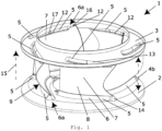
- FIG 1 is a perspective view of an impeller 1 of a radial fan for conveying a gaseous fluid, comprising a base plate 2, a cover plate 3, wherein the cover plate 3 is spaced from the base plate 2 in the axial direction of the impeller 1 and is arranged at a distance 4 between the base plate 2 and the cover plate 3, wherein the cover plate 3 and the base plate 2 have at least one embossed Bead 5, in particular a plurality of embossed beads 5, a plurality of blades 7, wherein at least one blade 7 is arranged between the cover disk 3 and the base disk 2 and is fastened in the region and in the course of at least one bead 5, wherein a surface course of the bead 5 follows a surface course of the blade fastened to the bead 5, at least in an envelope, such that a conveying effect of the bead 5 corresponds at least to a conveying effect of a blade surface 8 reduced due to the bead.
- the blade 7 can thereby advantageously be shortened and at the same time
- the blade 7 is arranged on the bead 5.
- the bead 5 is embossed along a contour of the blade 9, in particular along a contour of an edge region of the blade that is adjacent to the cover plate 3 or the base plate 2.
- the bead 5, in particular a bead outlet 6a of the bead 5 has a curvature-continuous transition into the base plate 2 and into the cover plate.
- a fastening 12 of the blade 7 is shown as an example formed by means of a welded connection, wherein the fastening 12 is shown arranged on the pressure side and suction side of the blade.
- the blade 5 is arranged between a pair of beads (not designated), wherein the pair of beads comprises a first bead 13 and a second bead 14, wherein the first bead 13 is formed on the cover disk 3 and the second bead 14 on the base disk 2.
- the pair of beads comprises a first bead 13 and a second bead 14, wherein the first bead 13 is formed on the cover disk 3 and the second bead 14 on the base disk 2.
- the fastening 12 is designed in several parts, with a first part of the fastening 16 of the blade 7 being designed between the blade 7 and the cover plate 3 and at least a second part of the fastening 17 being designed between the blade 7 and the bead 5.
- the stability of the blade 7 on the cover plate 3 can thus advantageously be improved.
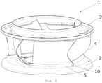
- FIG 2 is another perspective view of a wheel, analogous to Figure 1 , shown.
- a height 10 of the bead 5 varies in the radial direction of the impeller and increases towards the outside.
- Analogous to the Figures 1 and 2 is in Figure 3 shown how the height 10 of the bead 5 decreases towards the outside.
- the height of the bead 5 corresponds to a tenth, preferably an eighth, preferably a sixth part of the distance 4 between the base plate 2 and the cover plate 3. In this way, higher speeds and higher rotational speeds can be advantageously achieved with the same conveying capacity.
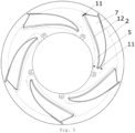
- Figure 4 is shown, analogous to the other figures, a top view of a base plate 2 with beads 5.
- a width 11 of the bead 5 varies in the radial direction of the impeller and decreases towards the outside. It is also shown that the bead 5 has a pressure-side profile, in particular a pressure-side contour profile, which deviates from a suction-side profile of the bead 5, in particular a suction-side contour profile of the bead 5.
- the bead 5 is parallel or profiled to the one in the Figures 1 to 3 illustrated blade 7 is formed.
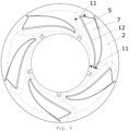
- FIG. 5 and 6 an axial top view of a base plate 2 with blades 7 arranged thereon by means of fastenings 12 is shown.
- the width 11 of the bead 5 takes up Figure 5 to the radially outer edge of the base plate 2, thus to the radially outer edge of the, for example, Figure 1 shown impeller 1.
- Figure 6 the embodiment analogous to Figure 5 in which the width 11 of the beads 5 decreases towards the edge, ie increases in the radial direction outwards.
Landscapes
- Engineering & Computer Science (AREA)
- Mechanical Engineering (AREA)
- General Engineering & Computer Science (AREA)
- Structures Of Non-Positive Displacement Pumps (AREA)
Applications Claiming Priority (1)
| Application Number | Priority Date | Filing Date | Title |
|---|---|---|---|
| DE102023116229.2A DE102023116229B4 (de) | 2023-06-21 | 2023-06-21 | Laufrad für Radiallüfter |
Publications (1)
| Publication Number | Publication Date |
|---|---|
| EP4481202A1 true EP4481202A1 (fr) | 2024-12-25 |
Family
ID=91331027
Family Applications (1)
| Application Number | Title | Priority Date | Filing Date |
|---|---|---|---|
| EP24178789.4A Pending EP4481202A1 (fr) | 2023-06-21 | 2024-05-29 | Roue pour ventilateur radial |
Country Status (4)
| Country | Link |
|---|---|
| US (1) | US20240426313A1 (fr) |
| EP (1) | EP4481202A1 (fr) |
| CN (1) | CN119177947A (fr) |
| DE (1) | DE102023116229B4 (fr) |
Families Citing this family (1)
| Publication number | Priority date | Publication date | Assignee | Title |
|---|---|---|---|---|
| DE102023133396A1 (de) | 2023-11-29 | 2025-06-05 | Ebm-Papst Mulfingen Gmbh & Co. Kg | Sickenschaufel-laufrad |
Citations (9)
| Publication number | Priority date | Publication date | Assignee | Title |
|---|---|---|---|---|
| DE1998178U (de) * | 1966-10-22 | 1968-12-12 | Roehrs Werner Dr Kg | Redialluefter-laufrad (trommellaeufer) mit umgebogenen schaufelbefestigungslaschen. |
| DE3247453C1 (de) * | 1982-12-22 | 1983-12-15 | Funken & Co GmbH, 5200 Siegburg | Ventilatorlaufrad und Verfahren zu seiner Herstellung |
| WO1999027258A1 (fr) * | 1997-11-21 | 1999-06-03 | Hermann Stahl Gmbh | Roue de ventilateur |
| JP3757802B2 (ja) * | 2001-02-09 | 2006-03-22 | 三菱電機株式会社 | ターボファン、およびターボファンを用いた送風装置、空気調和機 |
| EP2846046A1 (fr) | 2013-09-10 | 2015-03-11 | Punker GmbH | Roue de ventilateur |
| EP3203084A1 (fr) * | 2016-02-02 | 2017-08-09 | Punker GmbH | Roue de ventilateur et systeme de ventilateur |
| JP2018178795A (ja) * | 2017-04-07 | 2018-11-15 | 日清紡メカトロニクス株式会社 | ターボファン |
| WO2019001912A1 (fr) * | 2017-06-30 | 2019-01-03 | Ebm-Papst Mulfingen Gmbh & Co. Kg | Roue de soufflante |
| US20210148376A1 (en) * | 2017-06-30 | 2021-05-20 | Nidec Corporation | Impeller and blower |
Family Cites Families (23)
| Publication number | Priority date | Publication date | Assignee | Title |
|---|---|---|---|---|
| JP3291827B2 (ja) * | 1993-03-18 | 2002-06-17 | 株式会社日立製作所 | 羽根車及びディフューザ、並びにその製作方法 |
| DE19755065A1 (de) * | 1997-12-11 | 1999-06-17 | Asea Brown Boveri | Flügelrad |
| DE19831736C2 (de) * | 1998-07-15 | 2000-05-31 | Mtu Muenchen Gmbh | Verfahren zur Reparatur und Herstellung eines integral beschaufelten Rotors für eine Strömungsmaschine |
| CA2334071C (fr) * | 2000-02-23 | 2005-05-24 | Mitsubishi Heavy Industries, Ltd. | Aube mobile de turbine a gaz |
| US6419450B1 (en) * | 2001-05-21 | 2002-07-16 | Grundfos Pumps Manufacturing Corporation | Variable width pump impeller |
| DE10206447B4 (de) * | 2002-02-11 | 2004-06-03 | Mtu Aero Engines Gmbh | Verfahren und Vorrichtung zum Halten eines zu verbindenden, metallischen Bauteils und Verfahren zum Verbinden eines metallischen Bauteils mit einem weiteren Bauteil |
| JP2003328989A (ja) * | 2002-05-16 | 2003-11-19 | Hitachi Industries Co Ltd | 羽根車の製作方法 |
| GB2424200B (en) * | 2005-03-17 | 2007-10-24 | Rolls Royce Plc | Apparatus and method of manufacture of a component by hot isostatic pressing |
| WO2007037699A1 (fr) * | 2005-09-27 | 2007-04-05 | Umoe Mandal As | Ventilateur centrifuge |
| KR100847523B1 (ko) * | 2006-12-29 | 2008-07-22 | 엘지전자 주식회사 | 터보팬 |
| US20080279682A1 (en) * | 2007-03-06 | 2008-11-13 | Larry David Wydra | Impeller Assembly and Method of Using Same |
| US7762778B2 (en) * | 2007-05-17 | 2010-07-27 | Kurz-Kasch, Inc. | Fan impeller |
| EP2226508A1 (fr) * | 2009-03-06 | 2010-09-08 | Pompes Salmson | Procédé de fabrication d'une roue à aubes par emboutissage |
| US20110182736A1 (en) * | 2010-01-25 | 2011-07-28 | Larry David Wydra | Impeller Assembly |
| KR20130110440A (ko) * | 2012-03-29 | 2013-10-10 | 삼성전기주식회사 | 임펠러 및 이를 포함한 진공청소기 모터 어셈블리 |
| KR101790421B1 (ko) * | 2013-01-23 | 2017-10-25 | 컨셉츠 이티아이 인코포레이티드 | 터보머신들의 인접한 블레이드 요소들의 흐름장들의 결합을 가하는 구조들 및 방법들, 그리고 그들을 포함하는 터보머신들 |
| DE102013104534A1 (de) * | 2013-05-03 | 2014-11-06 | Hürner-Funken GmbH | Laufrad sowie Segment zu dessen Herstellung und Herstellungsverfahren für das Laufrad |
| DE102014006756A1 (de) * | 2014-05-05 | 2015-11-05 | Ziehl-Abegg Se | Laufrad für Diagonal- oder Radialventilatoren, Spritzgusswerkzeug zur Herstellung eines solchen Laufrades sowie Gerät mit einem solchen Laufrad |
| WO2016127225A1 (fr) * | 2015-02-09 | 2016-08-18 | Atlas Copco Airpower, Naamloze Vennootschap | Rotor de compresseur à moyeu creux et à nervures prolongeant des pales à l'intérieur du moyeu et procédé de fabrication d'un rotor de ce type |
| JP6931778B2 (ja) * | 2016-08-29 | 2021-09-08 | パナソニックIpマネジメント株式会社 | 温度調和システムおよび車両 |
| NL2018044B1 (en) * | 2016-12-22 | 2018-06-29 | Ihc Holland Ie Bv | Impeller with rotor blades for centrifugal pump |
| CN109404337B (zh) * | 2018-11-19 | 2024-10-15 | 珠海格力电器股份有限公司 | 离心风轮、空调及离心风轮的装配方法 |
| JP6982267B2 (ja) * | 2020-05-08 | 2021-12-17 | ダイキン工業株式会社 | クローズドインペラ及びクローズドインペラの製造方法 |
-
2023
- 2023-06-21 DE DE102023116229.2A patent/DE102023116229B4/de active Active
-
2024
- 2024-05-29 EP EP24178789.4A patent/EP4481202A1/fr active Pending
- 2024-06-18 CN CN202410782702.3A patent/CN119177947A/zh active Pending
- 2024-06-19 US US18/747,790 patent/US20240426313A1/en active Pending
Patent Citations (9)
| Publication number | Priority date | Publication date | Assignee | Title |
|---|---|---|---|---|
| DE1998178U (de) * | 1966-10-22 | 1968-12-12 | Roehrs Werner Dr Kg | Redialluefter-laufrad (trommellaeufer) mit umgebogenen schaufelbefestigungslaschen. |
| DE3247453C1 (de) * | 1982-12-22 | 1983-12-15 | Funken & Co GmbH, 5200 Siegburg | Ventilatorlaufrad und Verfahren zu seiner Herstellung |
| WO1999027258A1 (fr) * | 1997-11-21 | 1999-06-03 | Hermann Stahl Gmbh | Roue de ventilateur |
| JP3757802B2 (ja) * | 2001-02-09 | 2006-03-22 | 三菱電機株式会社 | ターボファン、およびターボファンを用いた送風装置、空気調和機 |
| EP2846046A1 (fr) | 2013-09-10 | 2015-03-11 | Punker GmbH | Roue de ventilateur |
| EP3203084A1 (fr) * | 2016-02-02 | 2017-08-09 | Punker GmbH | Roue de ventilateur et systeme de ventilateur |
| JP2018178795A (ja) * | 2017-04-07 | 2018-11-15 | 日清紡メカトロニクス株式会社 | ターボファン |
| WO2019001912A1 (fr) * | 2017-06-30 | 2019-01-03 | Ebm-Papst Mulfingen Gmbh & Co. Kg | Roue de soufflante |
| US20210148376A1 (en) * | 2017-06-30 | 2021-05-20 | Nidec Corporation | Impeller and blower |
Also Published As
| Publication number | Publication date |
|---|---|
| DE102023116229B4 (de) | 2026-02-26 |
| CN119177947A (zh) | 2024-12-24 |
| US20240426313A1 (en) | 2024-12-26 |
| DE102023116229A1 (de) | 2024-12-24 |
Similar Documents
| Publication | Publication Date | Title |
|---|---|---|
| EP0207457B1 (fr) | Roue de pompe à eau | |
| EP2761137B1 (fr) | Pale d'une rangée de pales de rotor ou de stator pour une turbomachine | |
| EP2478186B1 (fr) | Rotor de turbomachine | |
| EP3916239B1 (fr) | Roue de soufflerie pourvu de pales de rotor courbées tridimensionnelles | |
| EP2505783B1 (fr) | Rotor d'un étage de compresseur axial d'une turbomachine | |
| EP2921716B1 (fr) | Groupe de série d'aubes | |
| EP1875045B1 (fr) | Roue de turbine | |
| EP4481202A1 (fr) | Roue pour ventilateur radial | |
| DE19751729A1 (de) | Lüfterrad | |
| WO2013060358A1 (fr) | Roue de ventilateur axial | |
| DE19941133C1 (de) | Gebauter Leitkranz für eine Gasturbine, insbesondere ein Flugtriebwerk | |
| EP2410131B1 (fr) | Rotor d'une turbomachine | |
| EP3475580B1 (fr) | Disque de roue de ventilateur et roue de ventilateur | |
| WO2017009065A1 (fr) | Compresseur à canaux latéraux ou pompe à vide à canaux latéraux muni de bandes d'étanchéité d'entrée entre deux canaux annulaires qui se trouvent de chaque côté d'un disque de rotor | |
| EP1498612B1 (fr) | Pompe turbomoléculaire | |
| EP3592987B1 (fr) | Carter semi-hélicoïdal | |
| EP3183430B1 (fr) | Aube mobile de turbine | |
| DE102008056352A1 (de) | Vakuumpumpenrotor | |
| WO2018130690A1 (fr) | Roue de ventilateur à direction d'écoulement prédéfinie | |
| EP3885535B1 (fr) | Bague d'étanchéité pour un rotor et rotor doté d'une telle bague d'étanchéité | |
| DE102024123702B3 (de) | Laufrad für einen Ventilator | |
| DE102023133396A1 (de) | Sickenschaufel-laufrad | |
| DE102016209085A1 (de) | Radverkleidungsbaugruppe für ein Kraftfahrzeugrad, Kraftfahrzeug mit einer Radverkleidungsbaugruppe | |
| DE102007037012B4 (de) | Gebläseeinheit und handgetragenes Blasgerät | |
| DE102007016805A1 (de) | Axialventilator, insbesondere für die Kühlanlage eines Schienenfahrzeuges |
Legal Events
| Date | Code | Title | Description |
|---|---|---|---|
| PUAI | Public reference made under article 153(3) epc to a published international application that has entered the european phase |
Free format text: ORIGINAL CODE: 0009012 |
|
| STAA | Information on the status of an ep patent application or granted ep patent |
Free format text: STATUS: THE APPLICATION HAS BEEN PUBLISHED |
|
| AK | Designated contracting states |
Kind code of ref document: A1 Designated state(s): AL AT BE BG CH CY CZ DE DK EE ES FI FR GB GR HR HU IE IS IT LI LT LU LV MC ME MK MT NL NO PL PT RO RS SE SI SK SM TR |
|
| STAA | Information on the status of an ep patent application or granted ep patent |
Free format text: STATUS: REQUEST FOR EXAMINATION WAS MADE |
|
| 17P | Request for examination filed |
Effective date: 20250610 |