EP4481249A1 - Actionneur et procédé de réglage de grandeurs de réglage - Google Patents
Actionneur et procédé de réglage de grandeurs de réglage Download PDFInfo
- Publication number
- EP4481249A1 EP4481249A1 EP24183740.0A EP24183740A EP4481249A1 EP 4481249 A1 EP4481249 A1 EP 4481249A1 EP 24183740 A EP24183740 A EP 24183740A EP 4481249 A1 EP4481249 A1 EP 4481249A1
- Authority
- EP
- European Patent Office
- Prior art keywords
- actuator
- locking
- actuators
- eine
- fixing
- Prior art date
- Legal status (The legal status is an assumption and is not a legal conclusion. Google has not performed a legal analysis and makes no representation as to the accuracy of the status listed.)
- Pending
Links
Images


Classifications
-
- F—MECHANICAL ENGINEERING; LIGHTING; HEATING; WEAPONS; BLASTING
- F16—ENGINEERING ELEMENTS AND UNITS; GENERAL MEASURES FOR PRODUCING AND MAINTAINING EFFECTIVE FUNCTIONING OF MACHINES OR INSTALLATIONS; THERMAL INSULATION IN GENERAL
- F16K—VALVES; TAPS; COCKS; ACTUATING-FLOATS; DEVICES FOR VENTING OR AERATING
- F16K31/00—Actuating devices; Operating means; Releasing devices
- F16K31/004—Actuating devices; Operating means; Releasing devices actuated by piezoelectric means
-
- F—MECHANICAL ENGINEERING; LIGHTING; HEATING; WEAPONS; BLASTING
- F16—ENGINEERING ELEMENTS AND UNITS; GENERAL MEASURES FOR PRODUCING AND MAINTAINING EFFECTIVE FUNCTIONING OF MACHINES OR INSTALLATIONS; THERMAL INSULATION IN GENERAL
- F16K—VALVES; TAPS; COCKS; ACTUATING-FLOATS; DEVICES FOR VENTING OR AERATING
- F16K31/00—Actuating devices; Operating means; Releasing devices
- F16K31/02—Actuating devices; Operating means; Releasing devices electric; magnetic
- F16K31/025—Actuating devices; Operating means; Releasing devices electric; magnetic actuated by thermo-electric means
-
- F—MECHANICAL ENGINEERING; LIGHTING; HEATING; WEAPONS; BLASTING
- F16—ENGINEERING ELEMENTS AND UNITS; GENERAL MEASURES FOR PRODUCING AND MAINTAINING EFFECTIVE FUNCTIONING OF MACHINES OR INSTALLATIONS; THERMAL INSULATION IN GENERAL
- F16K—VALVES; TAPS; COCKS; ACTUATING-FLOATS; DEVICES FOR VENTING OR AERATING
- F16K31/00—Actuating devices; Operating means; Releasing devices
- F16K31/02—Actuating devices; Operating means; Releasing devices electric; magnetic
- F16K31/04—Actuating devices; Operating means; Releasing devices electric; magnetic using a motor
- F16K31/047—Actuating devices; Operating means; Releasing devices electric; magnetic using a motor characterised by mechanical means between the motor and the valve, e.g. lost motion means reducing backlash, clutches, brakes or return means
-
- F—MECHANICAL ENGINEERING; LIGHTING; HEATING; WEAPONS; BLASTING
- F16—ENGINEERING ELEMENTS AND UNITS; GENERAL MEASURES FOR PRODUCING AND MAINTAINING EFFECTIVE FUNCTIONING OF MACHINES OR INSTALLATIONS; THERMAL INSULATION IN GENERAL
- F16K—VALVES; TAPS; COCKS; ACTUATING-FLOATS; DEVICES FOR VENTING OR AERATING
- F16K35/00—Means to prevent accidental or unauthorised actuation
- F16K35/02—Means to prevent accidental or unauthorised actuation to be locked or disconnected by means of a pushing or pulling action
- F16K35/022—Means to prevent accidental or unauthorised actuation to be locked or disconnected by means of a pushing or pulling action the locking mechanism being actuated by a separate actuating element
-
- F—MECHANICAL ENGINEERING; LIGHTING; HEATING; WEAPONS; BLASTING
- F16—ENGINEERING ELEMENTS AND UNITS; GENERAL MEASURES FOR PRODUCING AND MAINTAINING EFFECTIVE FUNCTIONING OF MACHINES OR INSTALLATIONS; THERMAL INSULATION IN GENERAL
- F16K—VALVES; TAPS; COCKS; ACTUATING-FLOATS; DEVICES FOR VENTING OR AERATING
- F16K37/00—Special means in or on valves or other cut-off apparatus for indicating or recording operation thereof, or for enabling an alarm to be given
- F16K37/0025—Electrical or magnetic means
- F16K37/0041—Electrical or magnetic means for measuring valve parameters
-
- F—MECHANICAL ENGINEERING; LIGHTING; HEATING; WEAPONS; BLASTING
- F16—ENGINEERING ELEMENTS AND UNITS; GENERAL MEASURES FOR PRODUCING AND MAINTAINING EFFECTIVE FUNCTIONING OF MACHINES OR INSTALLATIONS; THERMAL INSULATION IN GENERAL
- F16K—VALVES; TAPS; COCKS; ACTUATING-FLOATS; DEVICES FOR VENTING OR AERATING
- F16K37/00—Special means in or on valves or other cut-off apparatus for indicating or recording operation thereof, or for enabling an alarm to be given
- F16K37/0025—Electrical or magnetic means
- F16K37/005—Electrical or magnetic means for measuring fluid parameters
-
- F—MECHANICAL ENGINEERING; LIGHTING; HEATING; WEAPONS; BLASTING
- F24—HEATING; RANGES; VENTILATING
- F24D—DOMESTIC- OR SPACE-HEATING SYSTEMS, e.g. CENTRAL HEATING SYSTEMS; DOMESTIC HOT-WATER SUPPLY SYSTEMS; ELEMENTS OR COMPONENTS THEREFOR
- F24D19/00—Details
- F24D19/10—Arrangement or mounting of control or safety devices
- F24D19/1006—Arrangement or mounting of control or safety devices for water heating systems
- F24D19/1009—Arrangement or mounting of control or safety devices for water heating systems for central heating
- F24D19/1015—Arrangement or mounting of control or safety devices for water heating systems for central heating using a valve or valves
- F24D19/1018—Radiator valves
-
- F—MECHANICAL ENGINEERING; LIGHTING; HEATING; WEAPONS; BLASTING
- F24—HEATING; RANGES; VENTILATING
- F24D—DOMESTIC- OR SPACE-HEATING SYSTEMS, e.g. CENTRAL HEATING SYSTEMS; DOMESTIC HOT-WATER SUPPLY SYSTEMS; ELEMENTS OR COMPONENTS THEREFOR
- F24D19/00—Details
- F24D19/10—Arrangement or mounting of control or safety devices
- F24D19/1006—Arrangement or mounting of control or safety devices for water heating systems
- F24D19/1009—Arrangement or mounting of control or safety devices for water heating systems for central heating
- F24D19/1015—Arrangement or mounting of control or safety devices for water heating systems for central heating using a valve or valves
- F24D19/1024—Arrangement or mounting of control or safety devices for water heating systems for central heating using a valve or valves a multiple way valve
- F24D19/103—Arrangement or mounting of control or safety devices for water heating systems for central heating using a valve or valves a multiple way valve bimetal operated
-
- F—MECHANICAL ENGINEERING; LIGHTING; HEATING; WEAPONS; BLASTING
- F24—HEATING; RANGES; VENTILATING
- F24D—DOMESTIC- OR SPACE-HEATING SYSTEMS, e.g. CENTRAL HEATING SYSTEMS; DOMESTIC HOT-WATER SUPPLY SYSTEMS; ELEMENTS OR COMPONENTS THEREFOR
- F24D2220/00—Components of central heating installations excluding heat sources
- F24D2220/02—Fluid distribution means
- F24D2220/0257—Thermostatic valves
Definitions
- the invention relates to an actuator and a method for adjusting control variables and is applicable in particular in control and regulation technology, for example in the operation of heating systems.
- Simple, commercially available actuators for heating surfaces such as underfloor heating systems only have two permanent states: either “open” or “closed”. And according to the current state of technology, one of these two states requires electrical current or another form of energy for the entire active period.
- the expansion drive has an expansion element and a spring element. If the expansion element expands due to external influences, its expansion is converted by the spring element into a force that rotates the window handle coupling and thus opens the window fittings.
- the invention is based on the object of creating an actuator which is versatile, easy and cost-effective to manufacture, has a clear mechanical and electrical structure and can be used in an energy-saving manner.
- the actuator according to the invention should also significantly reduce energy consumption in many areas of application, be able to fix any number of setpoints, manipulated variables or positions and have a significantly longer service life than known drives of this type.
- the method for adjusting manipulated variables is intended to ensure reliable and energy-efficient operation of the actuator according to the invention.
- the actuator according to the invention controls, for example, the flow of gases or liquids in pipes, or the setting angle of a wing, or the stroke of a valve and much more through the mechanical movement of an actuator or an actuating part such as a lever arm or a wheel.
- control element - or the control variable - can be transferred to a wide variety of applications.
- a particular advantage of the invention is that the setpoint values set with the actuator according to the invention do not require electrical current or any other form of energy to maintain them over their entire active period, in that the actuator has a first actuator designed as an expansion element and alternatively either a second actuator designed as an expansion element or as a spring element and comprises a mechanism for fixing setpoint values specified by a signal generator by means of a locking system.
- a further advantage of the invention is the variety of possible implementation forms and fields of application, in that the expansion elements are designed thermomechanically or electromechanically or bionic, whereby the expansion elements cause volume/length changes and the control variable is decoupled from the volume/length change after fixing.
- a significant advantage of the method according to the invention is that length and/or angle values specified as a target value are set via actuators by means of expansion elements by means of a signal transmitter and are subsequently fixed when the target value is reached, whereby no energy is required to maintain the fixation after fixation has taken place.
- control variable is decoupled from the volume/length change, and the fixation is carried out by means of a mechanism with a grid system.
- the fixation is cancelled by signals from the signal generator and new target values can be set.
- the fixation can take place automatically when the expansion elements are deactivated.
- An optimal procedure for adjusting the control variables is achieved by detecting the position of the actuators and transmitting it to a control device, and the control device compares the activities of the expansion elements with the setpoints to be controlled, whereby if no setpoints are to be changed, the system remains passive and thus saves energy and reduces its own wear.
- a preferred application of the invention is heating technology.
- An active thermal actuator for an underfloor heating system consumes approximately 1-2.5 watts of electrical energy.
- An apartment usually has several rooms, i.e. several actuators, a house several apartments, a city several houses throughout the entire heating period! This example of the technical function/principle of the actuator for underfloor heating systems is used in many other technical applications, in a similar form and in large numbers.
- the idea of the invention is based on the principle of volume or length changes of materials as a result of manipulation by external influences, as is typical for various expansion material drives (actuators).
- Expansion drives/actuators in the sense of our invention are based on the ability of certain materials to significantly change their volume or length as a result of an external influence. Typical examples of such influences are changes in temperature, humidity or electrical voltage. If these values increase, the volume or length of the material usually increases as well. If these values decrease, the volume or length usually decreases.
- the volume/length change of the expansion drives/actuators is directly dependent on the influence that causes this change. This is the reason for the constant energy consumption of, for example, thermal actuators for underfloor heating systems in one of the two states “closed” or “open”.
- the core of the present invention is the decoupling of the manipulated variable from its direct cause, the volume or length change of one or more actuators.
- the schematic structure of the actuator according to the invention can be described as follows: There is an actuator X, eg an expansion drive in the form of a cylinder or band. If this actuator X is caused to expand in a certain direction by an event, eg by switching on electrical energy, then it is able to push another element - eg a lever H - in front of it.
- an actuator X eg an expansion drive in the form of a cylinder or band. If this actuator X is caused to expand in a certain direction by an event, eg by switching on electrical energy, then it is able to push another element - eg a lever H - in front of it.
- the actuator is now caused to contract to its original state by a second event, e.g. switching off the electrical power, then the lever H remains at the reached position, e.g. 100% of the possible travel.
- the actuator X is not mechanically connected to the lever H and is therefore not able to pull the lever H back.
- the lever H remains where the actuator X pushed it, at 100% of the possible path.
- the lever H In this position, the lever H is fixed indefinitely by a suitable mechanism M. It can passively fix any setpoint, in this example the setpoint 100%. The actuator does not consume any energy in this state. If the setpoint remains constant over a period of time, then the actuator saves exactly as much energy as a conventional active actuator would need to hold this 100% position.
- the setpoint or manipulated variable should be reduced from 100% to 50%.
- a second actuator Y e.g. an elastic drive or a compression or tension spring. Due to its arrangement, the actuator Y is able to act in the opposite direction to actuator X. If the actuator Y is activated by an event, the fixation of the lever H is released simultaneously or with a time delay.
- the actuator Y then pushes the lever H in front of it until it has reached the target value of 50%.
- a control signal that signals that the target value of 50% has been reached switches off the extension of the actuator Y.
- the actuator Y returns to its original length if necessary.
- the lever H on the other hand, is fixed in the position reached by the mechanism M and controls the target value of 50% passively over the long term.
- a new event requires a different setpoint. If this new setpoint is greater than 50%, e.g. 75%, then actuator X sets the new position. If the new setpoint is less than 50%, then actuator Y regulates until the new position, e.g. 25%, is reached. Then mechanism M fixes the new position.
- the mechanism M automatically fixes the position of the lever H in any number of values between 0-100% as soon as the influence of the actuators ceases and the mechanism M receives a corresponding signal.
- This control logic compares the activity of the actuators X and Y with the setpoint or manipulated variable to be controlled. If no setpoints need to be changed, the system remains passively fixed, thereby saving energy and at the same time reducing its own wear.
- Fig. 00a shows the state of the art of a typical thermal actuator with the first possible setpoint or manipulated variable.
- Point P1 is at 0% of the travel.
- Fig. 00b shows the state of the art with the second possible setpoint or manipulated variable.
- Point P1 is at 100% of the travel.
- the passive, variable, fixing actuator according to the invention is described in the following embodiments in two different designs.
- the Z1 design works with a controllable actuator/expansion element and an uncontrolled, passive spring element as a counterforce.
- the Z1 design is the more compact and probably also the more cost-effective variant compared to the second design Z2.
- the Z2 design works with two separately controllable actuators/expansion elements. This enables more precise control of the setpoints or manipulated variables and possibly other advantages, among other things due to the elimination of the permanent spring tension.
- points P1, P2 and, if applicable, P3 are marked for tapping the mechanical control functions. There are any number of suitable positions at which this control function can be tapped according to requirements.
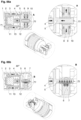
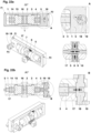
- the basis of the Z1 design is a first housing part 1 fixed to the application to be controlled.
- thermoelectric or inductive element manipulates the actual actuator, which in the illustrations consists of the abstracted parts 3 and 4 as an example.
- This actuator 3, 4 can consist of a thermally operating expansion element, for example. If this expansion element is manipulated, for example by heating the energy source on the energy converter 2, the actuator 3, 4 experiences a significant change in length. In the present embodiment, it expands.
- a locking mechanism A, B for example consisting of the parts first locking element 5, second locking element 8, locking drive 9 and locking spring 10, must first release the fixation of the working piston 5.
- the energy source on the energy converter 2 is deactivated, whereby the actuator 3, 4 ceases to work. Without a fixation, the strong spring 13 would push the actuator 3, 4 and the working piston 5 back to their original position.
- the gradation of the necessary/possible locking steps of the first and second locking elements 5 and 8 is primarily determined by the required positioning accuracy and the forces occurring. Examples are shown in the Fig. 01-07 seven possible fixing positions or steps.
- Fig. 04 The maximum possible target, actuating, control or working travel with fixed working piston 5 is shown statically as an example.
- the mechanical actuating function i.e. the travel and the force of the design Z1, can be used or taken at points P1 and P2 using suitable connections (not shown).
- a suitable sensor consisting for example of the transmitter 6 and receiver 7, is integrated. (see detail B in Fig. 01-07 )
- the values of the sensors 6, 7 can be interpreted by suitable systems (not shown) and used to monitor and change the setpoints.
- the second housing part 11 and the third housing part 12 should also be mentioned. They are firmly connected to the first housing part 1 and serve to support the overall function.
- the detailed structure of the entire housing can be derived from the Fig. 01-07 concept presented.
- Fig. 05a - Fig. 05b - shows the setpoint "passive, 100%, fixed”.
- Any setpoint or manipulated variable provided for by the design can be fixed in an energy-saving manner thanks to this simple structure and process.
- the Z2 designs do not work with a spring, but with a second, controllable actuator/expansion element.
- the advantages of the Z2 designs lie not only in the more precise control of the setpoints, but also in the lower wear, which can be achieved by eliminating the continuous load on the spring.
- the designs with two controllable actuators made it possible to create variants that are essentially similar but have different features in detail.
- the housing shapes and, if necessary, the actuating characteristics can be adapted to the given requirements by adjusting the angle of the two actuators to each other.
- Any other working angle of the actuators between 0 - 360° to each other is technically possible and may make sense.
- the travel ranges of both actuators can be controlled independently of each other.
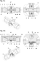
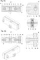
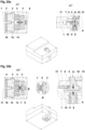
- Fig. 08-36 the four mentioned designs Z2 are shown in different, similar states/positions. It can be seen that the energy sources or energy converters 2, 16 and the actuator components 3, 4, 14, 15 are each present twice and act on a differently designed working piston 5.
- Fig. 08a and 08b shows the variant with counter-acting actuators directed 180° inwards, consisting of actuators 3, 4, 14, 15 in the static state.
- the setpoint is fixed at 50% of the travel by the locking mechanism A, B with the parts first locking element 5, second locking element 8, locking drive 9 and locking spring 10.
- the energy converters 2, 16 have no influence on the system and the actuators 3, 4, 14, 15 are in a passive state.
- the housing parts first housing part 1 and fourth housing part 17 are shown as examples in the perspective views for better understanding.
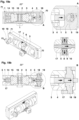
- Fig. 09a and 09b the energy converters 2, 16 are activated and have brought the actuators 4, 14 closer to the working piston 5.
- the working piston 5 remains fixed.
- the sensor consisting of sensor transmitter 6 and sensor receiver 7, is activated and can read the current position. (see arrows in detail B)
- the control value 50% can be taken off at points P1, P2 and P3.
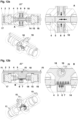
- Fig. 10a and 10b the working piston 5 is released/released by the locking mechanism A, B with the parts first locking element 5, second locking element 8, locking drive 9 and locking spring 10 and can be moved to a new position/setpoint by the action of the energy sources/energy converters 2, 16 with the help of the actuators 3, 4, 14, 15. During this process, the points P1, P2 and P3 change their position.
- the sensor 6, 7 can read the actual value over the entire dynamic process.
- Fig. 11a and 11b the actuator 3, 4 pushes the working piston 5 to the right due to the effect of the energy converter 2.
- the positions of the points P1, P2 and P3 change and the sensor 6, 7 reads the current position (see the movement of the arrows in detail B).
- the lever arm 19 in detail B illustrates the movement and the resulting possibilities as an example. (The principle of an eccentric is shown here)
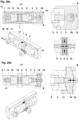
- Fig. 12a and 12b the sensor 6, 7 has detected/read the desired position and a control signal triggers the locking mechanism A, B with the parts first locking element 5, second locking element 8, locking drive 9 and locking spring 10.
- the points P1, P2 and P3 are fixed in a new position.
- Fig. 14a and 14b shows a passively fixed position on the left side.
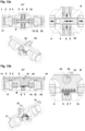
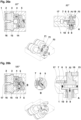
- Fig. 15a and 15b shows the variant with counter-acting actuators 3, 4, 14, 15 directed 180° outwards in the static state.
- the current setpoint or control variable is fixed in the middle of the possible travel (50%) by the locking mechanism A, B with the parts first locking element 5, second locking element 8, locking drive 9 and locking spring 10.
- the energy converters 2, 16 have no influence on the system and the actuators 3, 4, 14, 15 are in a passive state.
- the housing parts 1, 17 are shown as examples in the perspective views for better understanding.
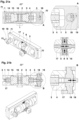
- Fig. 16a and 16b the energy converters 2, 16 are activated and have brought the parts 4, 14 closer to the working piston 5.
- the working piston 5 remains fixed.
- the sensor consisting of the transmitter 6 and receiver 7 is activated and can read the current position. (The abstract representation of its operation using the arrows as in PVF No. 02 has been omitted here).
- the control value '50% fixed' can be taken as an example at points P1, P2 and P3.
- Fig. 17a and 17b the working piston 5 is released/released by the locking mechanism A, B with the parts first locking element 5, second locking element 8, locking drive 9 and locking spring 10 and can be moved to a new setpoint or control value by the action of the energy converters 2, 16 with the help of the actuators 3, 4, 14, 15. During this process, the points P1, P2 and P3 change their position.
- the sensor 6, 7 can read the actual value over the entire dynamic process.
- Fig. 18a and 18b the actuator 3, 4 pushes the working piston 5 to the right due to the effect of the energy converter 2.
- the positions of the points P1, P2 and P3 change and the sensor 6, 7 reads the current position.
- Detail B shows the principle of an exemplary eccentric mechanism in section.
- the eccentric shaft 18, the lever arm 19 and the point P3 illustrate the movement that results from the use of the eccentric.
- the Fig. 18a and 18b show about 3 ⁇ 4 of the possible travel range unfixed.
- exemplary locking mechanism A, B closes with the parts first locking element 5, second locking element 8, locking drive 9 and locking spring 10 and fixes the current position 100% right'.
- Fig. 21a and 21b the energy converters 2, 16 and the actuators 3, 4, 14, 15 can be seen in their passive state.
- the points P1, P2 and P3 remain passively fixed, here '100% right'.
- Fig. 22a and 22b shows the passively fixed position '100% left'.
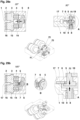
- Fig. 23a and 23b shows the variant with actuators 3, 4, 14, 15 acting next to each other in the same direction at an angle of 0° in the static state.
- the current setpoint is fixed in the middle of the possible travel (50%) by the locking mechanism A, B with the parts first locking element 5, second locking element 8, locking drive 9 and locking spring 10.
- the energy converters 2, 16 have no influence on the system and the actuators 3, 4, 14, 15 are in a passive state.
- the housing parts 1, 17 are shown as examples in the perspective views for better understanding.
- Fig. 24a and 24b the energy converters 2, 16 are activated and have brought the parts 4, 14 to the working piston 5.
- the working piston 5 remains fixed.
- the sensor consisting of sensor transmitter 6 and sensor receiver 7 is activated and can measure the current Read position. For example, the control value '50% fixed' can be read at points P1, P2 and P3.
- Fig. 25a and 25b the working piston 5 is released/released by the locking mechanism A, B with the parts first locking element 5, second locking element 8, locking drive 9 and locking spring 10 and can be moved to a new position/setpoint by the action of the energy converters 2, 16 using the actuators 3, 4, 14, 15. During this process, the points P1, P2 and P3 change their position.
- the sensor 6, 7 can read the actual value over the entire dynamic process.
- Fig. 28a and 28b the energy converters 2, 16 and the two actuators 3, 4, 14, 15 can be seen in their passive state.
- the points P1, P2 and P3 remain passively fixed, here '100% right'.
- Fig. 29a and 29b shows the passively fixed position '100% left'.
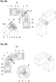
- Fig. 30a and 30b shows the variant with actuators 3, 4, 14, 15 acting at an angle of 90° to each other in the static state.
- the current setpoint is fixed in the middle of the possible travel (50%) by the locking mechanism A, B with the parts first locking element 5, second locking element 8, locking drive 9 and locking spring 10.
- the energy converters 2, 16 have no influence on the system and the actuators 3, 4, 14, 15 are in a passive state.
- the housing parts 1, 17 are shown as examples in the perspective views for better understanding.
- Fig. 31a and 31b the energy converters 2, 16 are activated and have brought the parts 4, 14 to the working piston 5.
- the working piston 5 remains fixed.
- the sensor consisting of sensor transmitter 6 and sensor receiver 7 is activated and can measure the current Read position. For example, the control value '50% fixed' can be read at points P1, P2 and P3.
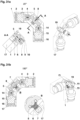
- Fig. 32a and 32b the working piston 5 is released/released by the locking mechanism A, B with the parts first locking element 5, second locking element 8, locking drive 9 and locking spring 10 and can be moved to a new position/setpoint by the action of the energy converters 2, 16 using the actuators 3, 4, 14, 15. During this process, the points P1, P2 and P3 change their position.
- the sensor 6, 7 can read the actual value over the entire dynamic process.
- Fig. 33a and 33b the actuator 3, 4 rotates the working piston 5 to the right due to the effect of the energy converter 2 (see arrows).
- the working piston 5 is axially mounted in this design and rotates around the center cross in Fig. 33a 00°.
- the positions of the points P1, P2 and P3 change and the sensor 6, 7 reads the current position (see small symbolic arrows in Fig. 33b Detail B).
- the two perspective views illustrate the rotation of the lever arm 19. Shown here is '100%, right, unfixed' of the possible travel.
- Fig. 35a and 35b the energy converters 2, 16 and the two actuators 3, 4, 14, 15 can be seen in their passive state.
- the points P1, P2 and P3 remain passively fixed, here '100% right'.
- the locking mechanism A, B with the parts first locking element 5, second locking element 8, locking drive 9 and locking spring 10 is described in more detail below.
- the concept of the actuator according to the invention can be adapted to the respective requirements in terms of its structural design, strength and size.
- the typical spectrum of the performance of thermal actuators for example, ranges from around 100 to 1500 Newtons (approx. 150 kg) actuating force with a maximum stroke of around 5 to 25 millimeters.
- the locking mechanism can, for example, consist of a linear tooth profile - as can be seen on the working piston 5 - and a matching counterpart locking element 8.
- the counterpart locking element 8 is pressed or pulled into the tooth profile of the working piston 5, e.g. by a spring 10, and thus passively blocks the change in the setpoint or control variable.
- the fixation is released by pulling or pushing the counterpart 8 out of the tooth profile of the working piston 5 using a suitable ratchet drive 9, e.g. an electric coil.
- a suitable ratchet drive e.g. an electric coil.
- the sensor - consisting of the parts sensor transmitter 6 and sensor receiver 7 - is described in more detail below.
- the sensor 6, 7 generally serves to determine the current, actual position of the working piston 5 with the points P1, P2, P3 and to compare the actual value with the setpoint or manipulated variable.
- One suitable sensor group is certainly the resistive sensors, i.e. sensors that can measure changes in electrical resistance, for example.
- any other mode of operation such as mechanical, capacitive, inductive, magnetic, piezoelectric, thermoelectric or optical, is also conceivable and may be useful.
- Fig. 09b shown as examples in detail B and the following.
- the sensor is followed by a suitable signal processing/evaluation system using different, but mostly electrical/electronic systems.
- a logic unit that reads the sensor signals regulates the setpoint or manipulated variable for P1, P2, P3.
Landscapes
- Engineering & Computer Science (AREA)
- General Engineering & Computer Science (AREA)
- Mechanical Engineering (AREA)
- Control Of Position Or Direction (AREA)
Applications Claiming Priority (1)
| Application Number | Priority Date | Filing Date | Title |
|---|---|---|---|
| DE102023116549.6A DE102023116549A1 (de) | 2023-06-23 | 2023-06-23 | Stellantrieb und Verfahren zum Verstellen von Stellgrößen |
Publications (1)
| Publication Number | Publication Date |
|---|---|
| EP4481249A1 true EP4481249A1 (fr) | 2024-12-25 |
Family
ID=91664067
Family Applications (1)
| Application Number | Title | Priority Date | Filing Date |
|---|---|---|---|
| EP24183740.0A Pending EP4481249A1 (fr) | 2023-06-23 | 2024-06-21 | Actionneur et procédé de réglage de grandeurs de réglage |
Country Status (2)
| Country | Link |
|---|---|
| EP (1) | EP4481249A1 (fr) |
| DE (1) | DE102023116549A1 (fr) |
Citations (10)
| Publication number | Priority date | Publication date | Assignee | Title |
|---|---|---|---|---|
| DE2948637A1 (de) | 1979-12-04 | 1981-06-11 | Hans-Joachim 6480 Wächtersbach Frei | Heizungssteuerungseinrichtung |
| DE3217415A1 (de) * | 1982-05-08 | 1983-11-10 | Hellmuth 3320 Salzgitter Möhlenhoff | Schaltungsanordnung zum ferngesteuerten betaetigen mindestens eines ventils einer heizungsanlage und damit ausgeruestete vorrichtung |
| WO2002086316A1 (fr) * | 2001-04-19 | 2002-10-31 | Bayerische Motorenwerke Ag | Mecanisme de commande realise dans un materiau a memoire de forme |
| US20060145544A1 (en) * | 2004-09-21 | 2006-07-06 | Browne Alan L | Active material based actuators for large displacements and rotations |
| DE102006006241A1 (de) * | 2006-02-09 | 2007-08-16 | Otto Egelhof Gmbh & Co. Kg | Linearbewegungsaktuator |
| US20080018198A1 (en) * | 2006-02-09 | 2008-01-24 | Juergen Sohn | Linear motion actuator |
| EP1546554B1 (fr) * | 2002-07-24 | 2008-10-22 | M 2 Medical A/S | Actionneur en alliage a memoire de forme |
| DE102015105542A1 (de) * | 2015-04-10 | 2016-10-13 | Otto Egelhof Gmbh & Co. Kg | Stellantrieb zur Ansteuerung einer Stellbewegung |
| US20200224785A1 (en) * | 2017-07-14 | 2020-07-16 | Bifold Fluidpower Limited | Failsafe valve actuator |
| EP3665542B1 (fr) * | 2017-10-10 | 2020-12-02 | EUT Edelstahl Umformtechnik GmbH | Dispositif de réglage autorégulé pour une vanne de régulation de fluide, système de thermorégulation et un système de distribution comprenant celui-ci, ainsi que procédé associé |
Family Cites Families (2)
| Publication number | Priority date | Publication date | Assignee | Title |
|---|---|---|---|---|
| DE102007053741B4 (de) * | 2007-11-12 | 2020-01-30 | ABUS Seccor GmbH | Elektronisches Schließ-System mit Memorymetall-Aktor |
| DE102020114284B3 (de) * | 2020-05-28 | 2021-01-28 | Michael Weltzer | Fenstergriffkupplung mit Dehnstoffantrieb und Fenster mit Fenstergriffkupplung |
-
2023
- 2023-06-23 DE DE102023116549.6A patent/DE102023116549A1/de active Pending
-
2024
- 2024-06-21 EP EP24183740.0A patent/EP4481249A1/fr active Pending
Patent Citations (10)
| Publication number | Priority date | Publication date | Assignee | Title |
|---|---|---|---|---|
| DE2948637A1 (de) | 1979-12-04 | 1981-06-11 | Hans-Joachim 6480 Wächtersbach Frei | Heizungssteuerungseinrichtung |
| DE3217415A1 (de) * | 1982-05-08 | 1983-11-10 | Hellmuth 3320 Salzgitter Möhlenhoff | Schaltungsanordnung zum ferngesteuerten betaetigen mindestens eines ventils einer heizungsanlage und damit ausgeruestete vorrichtung |
| WO2002086316A1 (fr) * | 2001-04-19 | 2002-10-31 | Bayerische Motorenwerke Ag | Mecanisme de commande realise dans un materiau a memoire de forme |
| EP1546554B1 (fr) * | 2002-07-24 | 2008-10-22 | M 2 Medical A/S | Actionneur en alliage a memoire de forme |
| US20060145544A1 (en) * | 2004-09-21 | 2006-07-06 | Browne Alan L | Active material based actuators for large displacements and rotations |
| DE102006006241A1 (de) * | 2006-02-09 | 2007-08-16 | Otto Egelhof Gmbh & Co. Kg | Linearbewegungsaktuator |
| US20080018198A1 (en) * | 2006-02-09 | 2008-01-24 | Juergen Sohn | Linear motion actuator |
| DE102015105542A1 (de) * | 2015-04-10 | 2016-10-13 | Otto Egelhof Gmbh & Co. Kg | Stellantrieb zur Ansteuerung einer Stellbewegung |
| US20200224785A1 (en) * | 2017-07-14 | 2020-07-16 | Bifold Fluidpower Limited | Failsafe valve actuator |
| EP3665542B1 (fr) * | 2017-10-10 | 2020-12-02 | EUT Edelstahl Umformtechnik GmbH | Dispositif de réglage autorégulé pour une vanne de régulation de fluide, système de thermorégulation et un système de distribution comprenant celui-ci, ainsi que procédé associé |
Also Published As
| Publication number | Publication date |
|---|---|
| DE102023116549A1 (de) | 2024-12-24 |
Similar Documents
| Publication | Publication Date | Title |
|---|---|---|
| EP2004428B1 (fr) | Soupape de commande | |
| DE60308538T2 (de) | Ventil für Raumfahrtanwendungen mit SMA-AKTOR | |
| EP2743552B1 (fr) | Soupape | |
| EP2405166B1 (fr) | Soupape électromagnétique | |
| DE102015110186A1 (de) | Stellantrieb für eine Kupplung, insbesondere eines Kraftfahrzeugs | |
| DE102017111726A1 (de) | Kolbenschieberventil | |
| EP1199501B1 (fr) | Actionneur d'une soupape, en particulier une soupape de turbine | |
| EP2868953B1 (fr) | Soupape | |
| EP4481249A1 (fr) | Actionneur et procédé de réglage de grandeurs de réglage | |
| DE102013225530A1 (de) | Haushaltsgerät mit einem Magnetventil | |
| DE102016005003A1 (de) | Bremsvorrichtung für linearachsengeführte Systeme | |
| EP2312187A1 (fr) | Appareil avec une partie de levage réglable linéairement | |
| EP3737882A1 (fr) | Entraînement de soupape présentant une fonction de déplacement rapide | |
| DE102013106215A1 (de) | Kolbenschieberventil | |
| EP3184867A1 (fr) | Vanne coaxiale à commande directe, équilibrée en pression comprenant un entraînement en cascade | |
| EP3064687B1 (fr) | Unite d'actionnement de porte | |
| DE102007028563A1 (de) | Kühlanlage | |
| DE102013016759A1 (de) | Anordnung zur Ansteuerung eines Getriebebremszylinders | |
| DE2138538C2 (de) | Verschlußeinrichtung für Luft öffnungen oder dergleichen | |
| DE102021115132A1 (de) | Ventilvorrichtung | |
| EP2859233A2 (fr) | Actionneur pour actionner un élément de commande | |
| DE102015225858A1 (de) | Schaltventil, insbesondere für ein Hydrauliksystem | |
| DE102007022059A1 (de) | Hubmagnetanordnung | |
| DE102013225537A1 (de) | Haushaltsgerät mit einem Magnetventil | |
| DE102009032374B3 (de) | Druckregelventil |
Legal Events
| Date | Code | Title | Description |
|---|---|---|---|
| PUAI | Public reference made under article 153(3) epc to a published international application that has entered the european phase |
Free format text: ORIGINAL CODE: 0009012 |
|
| STAA | Information on the status of an ep patent application or granted ep patent |
Free format text: STATUS: THE APPLICATION HAS BEEN PUBLISHED |
|
| AK | Designated contracting states |
Kind code of ref document: A1 Designated state(s): AL AT BE BG CH CY CZ DE DK EE ES FI FR GB GR HR HU IE IS IT LI LT LU LV MC ME MK MT NL NO PL PT RO RS SE SI SK SM TR |
|
| STAA | Information on the status of an ep patent application or granted ep patent |
Free format text: STATUS: REQUEST FOR EXAMINATION WAS MADE |
|
| 17P | Request for examination filed |
Effective date: 20250623 |