EP4481255A2 - Rohrelement mit klemmnut - Google Patents
Rohrelement mit klemmnut Download PDFInfo
- Publication number
- EP4481255A2 EP4481255A2 EP24210754.8A EP24210754A EP4481255A2 EP 4481255 A2 EP4481255 A2 EP 4481255A2 EP 24210754 A EP24210754 A EP 24210754A EP 4481255 A2 EP4481255 A2 EP 4481255A2
- Authority
- EP
- European Patent Office
- Prior art keywords
- sub
- longitudinal axis
- coupling
- respect
- oriented
- Prior art date
- Legal status (The legal status is an assumption and is not a legal conclusion. Google has not performed a legal analysis and makes no representation as to the accuracy of the status listed.)
- Pending
Links
Images



Classifications
-
- F—MECHANICAL ENGINEERING; LIGHTING; HEATING; WEAPONS; BLASTING
- F16—ENGINEERING ELEMENTS AND UNITS; GENERAL MEASURES FOR PRODUCING AND MAINTAINING EFFECTIVE FUNCTIONING OF MACHINES OR INSTALLATIONS; THERMAL INSULATION IN GENERAL
- F16L—PIPES; JOINTS OR FITTINGS FOR PIPES; SUPPORTS FOR PIPES, CABLES OR PROTECTIVE TUBING; MEANS FOR THERMAL INSULATION IN GENERAL
- F16L21/00—Joints with sleeve or socket
- F16L21/06—Joints with sleeve or socket with a divided sleeve or ring clamping around the pipe ends
- F16L21/065—Joints with sleeve or socket with a divided sleeve or ring clamping around the pipe ends tightened by tangentially-arranged threaded pins
-
- F—MECHANICAL ENGINEERING; LIGHTING; HEATING; WEAPONS; BLASTING
- F16—ENGINEERING ELEMENTS AND UNITS; GENERAL MEASURES FOR PRODUCING AND MAINTAINING EFFECTIVE FUNCTIONING OF MACHINES OR INSTALLATIONS; THERMAL INSULATION IN GENERAL
- F16L—PIPES; JOINTS OR FITTINGS FOR PIPES; SUPPORTS FOR PIPES, CABLES OR PROTECTIVE TUBING; MEANS FOR THERMAL INSULATION IN GENERAL
- F16L21/00—Joints with sleeve or socket
- F16L21/06—Joints with sleeve or socket with a divided sleeve or ring clamping around the pipe ends
-
- F—MECHANICAL ENGINEERING; LIGHTING; HEATING; WEAPONS; BLASTING
- F16—ENGINEERING ELEMENTS AND UNITS; GENERAL MEASURES FOR PRODUCING AND MAINTAINING EFFECTIVE FUNCTIONING OF MACHINES OR INSTALLATIONS; THERMAL INSULATION IN GENERAL
- F16L—PIPES; JOINTS OR FITTINGS FOR PIPES; SUPPORTS FOR PIPES, CABLES OR PROTECTIVE TUBING; MEANS FOR THERMAL INSULATION IN GENERAL
- F16L17/00—Joints with packing adapted to sealing by fluid pressure
- F16L17/02—Joints with packing adapted to sealing by fluid pressure with sealing rings arranged between outer surface of pipe and inner surface of sleeve or socket
- F16L17/04—Joints with packing adapted to sealing by fluid pressure with sealing rings arranged between outer surface of pipe and inner surface of sleeve or socket with longitudinally split or divided sleeve
-
- F—MECHANICAL ENGINEERING; LIGHTING; HEATING; WEAPONS; BLASTING
- F16—ENGINEERING ELEMENTS AND UNITS; GENERAL MEASURES FOR PRODUCING AND MAINTAINING EFFECTIVE FUNCTIONING OF MACHINES OR INSTALLATIONS; THERMAL INSULATION IN GENERAL
- F16L—PIPES; JOINTS OR FITTINGS FOR PIPES; SUPPORTS FOR PIPES, CABLES OR PROTECTIVE TUBING; MEANS FOR THERMAL INSULATION IN GENERAL
- F16L17/00—Joints with packing adapted to sealing by fluid pressure
- F16L17/06—Joints with packing adapted to sealing by fluid pressure with sealing rings arranged between the end surfaces of the pipes or flanges or arranged in recesses in the pipe ends or flanges
-
- B—PERFORMING OPERATIONS; TRANSPORTING
- B21—MECHANICAL METAL-WORKING WITHOUT ESSENTIALLY REMOVING MATERIAL; PUNCHING METAL
- B21D—WORKING OR PROCESSING OF SHEET METAL OR METAL TUBES, RODS OR PROFILES WITHOUT ESSENTIALLY REMOVING MATERIAL; PUNCHING METAL
- B21D17/00—Forming single grooves in sheet metal or tubular or hollow articles
- B21D17/04—Forming single grooves in sheet metal or tubular or hollow articles by rolling
Definitions
- This invention concerns improved groove shapes for pipe elements joined by mechanical couplings, and coupling key shapes compatible with improved groove shapes.
- one type of prior art mechanical coupling 10 for joining pipe elements 12 and 14 end to end relies on arcuate projections, known as keys 16 that mechanically engage circumferential grooves 18 in the pipe elements. While these couplings have proved to be very effective and efficient, the prior art configuration is subject to certain limitations. For example, when such a joint is subjected to loads, especially loads arising from internal pressure induced end loads, axial tensile forces and bending, the joint may not be able to withstand such loads up to the full tensile strength of certain types of pipe.
- external rings containing grooves may be welded to pipe elements to provide for mechanical engagement with the coupling's keys in a configuration that does not alter the pipe element's sidewall, either by removing material (machined grooves) or by deforming the sidewall (rolled grooves).
- the invention concerns a pipe element having first and second oppositely disposed ends.
- the pipe element comprises a sidewall surrounding a longitudinal axis and defining a bore.
- the sidewall has an outer surface.
- a first groove is positioned in the outer surface.
- the first groove extends circumferentially around the bore and is positioned proximate to the first end.
- the first groove is defined by a first plurality of sub-surfaces of the outer surface including:
- the first sub-surface has an orientation angle from 80° to 90° with respect to the longitudinal axis. Further by way of example, the first sub-surface has an orientation angle of 89° with respect to the longitudinal axis. In another example, the third sub-surface has an orientation angle from 1° to 25° with respect to the longitudinal axis. In a further example, the third sub-surface has an orientation angle of 10° with respect to the longitudinal axis. In another example the second sub-surface has an orientation angle of 90° with respect to the longitudinal axis. Further by way of example, the second sub-surface has an orientation angle from 40° to 70° with respect to the longitudinal axis. In an example embodiment the second sub-surface has an orientation angle of 50° with respect to the longitudinal axis. In a further example embodiment the fourth sub-surface has an orientation angle from +5° to -5° with respect to the longitudinal axis.
- the pipe element further comprises a second groove positioned in the outer surface.
- the second groove extends circumferentially around the bore and positioned proximate to the second end.
- the second groove is defined by a second plurality of sub-surfaces of the outer surface including:
- first and fifth sub-surfaces have an orientation angle from 80° to 90° with respect to the longitudinal axis. Further by way of example, the first and fifth sub-surfaces have an orientation angle 89° with respect to the longitudinal axis. In another example, the third and seventh sub-surfaces have an orientation angle from 1° to 25° with respect to the longitudinal axis. By way of further example, the third and seventh sub-surfaces have an orientation angle of 10° with respect to the longitudinal axis. In another example, the second and sixth sub-surfaces have an orientation angle of 90° with respect to the longitudinal axis. In another example, the second and sixth sub-surfaces have an orientation angle from 40° to 70° with respect to the longitudinal axis. Further by way of example, the second and sixth sub-surfaces have an orientation angle of 50° with respect to the longitudinal axis. In another example, the fourth and eighth sub-surfaces have an orientation angle from +5° to -5° with respect to the longitudinal axis.
- the invention further encompasses, in combination, a pipe element as described above and a coupling.
- the coupling comprises a plurality of segments attached to one another end to end surrounding the first end of the pipe element.
- Adjustable attachment members are positioned at each end of the segments for attaching the segments to one another.
- At least one arcuate projection is positioned on one side of each of the segments and engages with the first groove.
- the at least one arcuate projection comprises a plurality of mating surfaces including:
- a gap is positioned between the fourth mating surface and the fourth sub-surface.
- the at least one arcuate projection comprises a recess therein forming the gap between fourth mating surface and the fourth sub-surface.
- a further example embodiment comprises, in combination, a pipe element as described above and a coupling.
- the coupling comprises a plurality of segments attached to one another end to end surrounding the first end of the pipe element.
- Adjustable attachment members are positioned at each end of the segments for attaching the segments to one another.
- At least one arcuate projection is positioned on one side of each of the segments and engages with the first groove.
- the at least one arcuate projection comprises a plurality of mating surfaces including:
- a gap is positioned between the fourth mating surface and the fourth sub-surface.
- the at least one arcuate projection comprises a recess therein forming the gap between the fourth mating surface and the fourth sub-surface.
- the coupling comprises no more than two segments.
- the invention also encompasses a coupling for joining pipe elements.
- the coupling comprises a plurality of segments attached to one another end to end surrounding a central space for receiving the pipe elements.
- Adjustable attachment members are positioned at each end of the segments for attaching the segments to one another.
- At least a first arcuate projection is positioned on a first side of each of the segments.
- the first arcuate projections comprise a plurality of mating surfaces including:
- the first mating surface has an orientation angle from 80° to 90° with respect to the longitudinal axis. In another example embodiment the first mating surface has an orientation angle of 89° with respect to the longitudinal axis.
- the third mating surface has an orientation angle from 1° to 25° relative to the longitudinal axis. In another example the third mating surface has an orientation angle of 10° relative to the longitudinal axis.
- the second mating surface has an orientation angle of 90° with respect to the longitudinal axis. In another example the second mating surface has an orientation angle from 40° to 70° relative to the longitudinal axis. Further by way of example the second mating surface has an orientation angle of 50° relative to the longitudinal axis.
- the fourth mating surface has an orientation angle from +5° to -5° with respect to the longitudinal axis.
- the first and fifth mating surfaces have an orientation angle from 80° to 90° with respect to the longitudinal axis. Further by way of example, the first and fifth mating surfaces have an orientation angle of 89° with respect to the longitudinal axis.
- the third and seventh mating surfaces have an orientation angle from 1° to 25° relative to the longitudinal axis. Further by way of example, the third and seventh mating surfaces have an orientation angle of 10° relative to the longitudinal axis. Also by way of example, the second and sixth mating surfaces have an orientation angle of 90° with respect to the longitudinal axis.
- the second and sixth mating surfaces have an orientation angle from 40° to 70° relative to the longitudinal axis. In a further example, the second and sixth mating surfaces have an orientation angle of 50° relative to the longitudinal axis. In another example, the fourth and eighth mating surfaces have an orientation angle from +5° to -5° with respect to the longitudinal axis.
- the invention also encompasses, in combination, a coupling as described above and a pipe element.
- the pipe element comprises a sidewall surrounding the longitudinal axis and defining a bore.
- the sidewall has an outer surface.
- a first groove is positioned in the outer surface.
- the first groove extends circumferentially around the bore and is positioned proximate to the first end.
- the first groove is defined by a first plurality of sub-surfaces of the outer surface including:
- a gap is positioned between the fourth mating surface and the fourth sub-surface.
- the first arcuate projection comprises a recess therein forming the gap between the fourth mating surface and the fourth sub-surface.
- Another example embodiment comprises, in combination, a coupling as described above and a pipe element.
- the pipe element comprises:
- a gap is positioned between the fourth mating surface and the fourth sub-surface.
- the first arcuate projection comprises a recess therein forming the gap between the fourth mating surface and the fourth sub-surface.
- the coupling comprises no more than two segments.
- the invention also encompasses a method of assembling a coupling having an arcuate projection with a pipe element.
- the method comprises:
- the invention also encompasses a method of using a coupling having an arcuate projection engaged with a groove of a pipe element.
- the method comprises: applying a tensile force between the pipe element and the coupling, thereby causing a portion of the arcuate projection to engage the first sub-surface and another portion of the arcuate projection to engage the third sub-surface.
- each segment (26 being shown in section) has two arcuate projections, also known as keys 50 and 52 positioned on opposite sides of each segment. Keys 52 and 50 project toward the central space 30 and mechanically engage respective circumferential grooves 54 and 88 in each pipe element.
- a fluid tight joint is ensured by a ring seal 56 captured and compressed between the segments 26 and 28 and the pipe elements 22 and 24 when fasteners 44 (see Figure 2 ) are adjustably tightened to draw the segments 26 and 28 toward one another and into engagement with the pipe elements to form the joint.
- FIG 4 shows pipe element 24 and its groove 54 in detail.
- pipe element 24 comprises a sidewall 58 surrounding a longitudinal axis 60 and defining a bore 62.
- Groove 54 is positioned in an outer surface 64 of the sidewall 58.
- Groove 54 extends circumferentially about the bore 62 and is positioned proximate to an end 66 of the pipe element 24.
- the position of the groove 54 with respect to the pipe end 66 is coordinated with the coupling 20 so as to provide lands 70 for sealing engagement with the glands 72 of the ring seal 56.
- groove 54 comprises a first sub-surface 74 shown oriented perpendicular (90°) relative to the longitudinal axis 60.
- the orientation angle 73 of first sub-surface 74 may range from 80° to 90° with respect to the longitudinal axis 60, with an orientation angle of about 89° being advantageous.
- First sub-surface 74 faces away from the end 66 of the pipe element 24.
- a second sub-surface 76 is oriented at an angle with respect to the longitudinal axis 60. Second sub-surface 76 is positioned in spaced relation away from the first sub-surface 74 and faces the end 66 of the pipe element 24.
- a third sub-surface 78 is contiguous with the first sub-surface 74, is oriented at an angle with respect to the longitudinal axis 60 and slopes toward the second sub-surface 76.
- a fourth sub-surface 80 is contiguous with both the second and third sub-surfaces.
- the fourth sub-surface 80 is shown oriented parallel (0° angle) to the longitudinal axis 60, but its orientation angle 79 may range from +5° to -5° for a practical design.
- the terms "perpendicular”, “parallel” and “oriented at an angle” mean perpendicular or parallel or oriented at an angle with respect to a reference axis within normal manufacturing tolerances for the pipe element in question.
- second sub-surface 76 may have an orientation angle 82 from about 40° to about 70° relative to the longitudinal axis 60; an orientation angle 82 of about 50° is considered advantageous for certain applications.
- the third sub-surface 78 may have an orientation angle 84 from about 1° to about 25° relative to the longitudinal axis 60, and an orientation angle 84 of about 10° is considered advantageous for certain applications.
- pipe element 24 may have a second end 86 oppositely disposed from the end 66 (which may thus be considered the "first" end), the second end 86 having a second groove 88 with a groove configuration similar to the first groove 54.
- second groove 88 comprises a fifth sub-surface 90 shown oriented perpendicular (90°) to the longitudinal axis 60.
- the orientation angle 91 of fifth sub-surface 90 may range from 80° to 90° with respect to the longitudinal axis 60, with an orientation angle of about 89° being advantageous.
- Fifth sub-surface 90 faces away from the second end 86 of the pipe element 24.
- a sixth sub-surface 92 is oriented at an angle with respect to the longitudinal axis 60.
- Sixth sub-surface 92 is positioned in spaced relation away from the fifth sub-surface 90 and faces the second end 86 of the pipe element 24.
- a seventh sub-surface 94 is contiguous with the fifth sub-surface 90, is oriented at an angle with respect to the longitudinal axis 60 and slopes toward the sixth sub-surface 92.
- An eighth sub-surface 96 is contiguous with both the sixth and seventh sub-surfaces. The eighth sub-surface 96 is shown oriented parallel (0° angle) to the longitudinal axis 60, but its orientation angle 97 may range from about +5° to about -5° for a practical design.
- the outer roller 105 being an idler, is usually forced toward the inner roller 101 with a hydraulic ram 113, deforming the pipe element and forming the groove 54 having a shape dictated by the shapes of the inner and outer rollers 101 and 105.
- Grooves 54 and 88 may also be formed by machining operations.
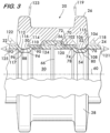
- Figures 2 and 3 show a combination pipe element (22 and/or 24) and coupling 20 connecting the pipe elements end to end.
- Figure 3 shows in detail, the cross sectional geometry of the arcuate projections or keys 50 and 52 effecting mechanical engagement with circumferential grooves 88 and 54 in each pipe element 22 and 24 initially upon assembly of the joint, i.e. prior to the application of internal pressure induced end loads, axial tensile forces and bending loads.
- key 52 comprises a plurality of mating surfaces including a first mating surface 102 shown oriented perpendicular to the longitudinal axis 60 and in facing relation with the first sub-surface 74. Note initially upon assembly there usually will be a gap between first mating surface 102 and first sub-surface 74 because the angular relationship between sub-surface 78 and sub-surface 80 tends to bias the location of key 52 away from sub-surface 74 .
- a second mating surface 104 is oriented at an angle with respect to the longitudinal axis 60, is spaced away from the first mating surface 102, and contacts the second sub-surface 76 initially upon assembly.
- a third mating surface 106 is oriented at an angle with respect to the longitudinal axis 60 and is contiguous with the first mating surface 102. Third mating surface 106 contacts third sub-surface 78 initially upon assembly.
- a fourth mating surface 108 is between the second and third mating surfaces 104 and 106, is in facing relation with the fourth sub-surface 80 and in spaced apart relation therefrom thereby forming a gap 115. The gap 115 is ensured by the fourth mating surface 108 comprising a recess in the arcuate projection (key) 52.
- key 50 also comprises a plurality of mating surfaces including a fifth mating surface 110 shown oriented perpendicular to the longitudinal axis 60 and in facing relation with the fifth sub-surface 90.
- An eighth mating surface 116 is between the sixth and seventh mating surfaces 112 and 114, is in facing relation with the eighth sub-surface 96 and in spaced apart relation therefrom thereby forming a gap 117.
- the gap 117 is ensured by the eighth mating surface 116 comprising a recess in the arcuate projection (key) 50.
- the mating surfaces will have orientation angles matched to the respective sub-surfaces they contact.
- the first mating surface 102 may have an orientation angle 119 from about 80° to about 90° with respect to the longitudinal axis 60, with an orientation angle of about 89° being advantageous.
- the second mating surface 104 may have an orientation angle 118 from about 40° to about 70° with respect to the longitudinal axis 60. An orientation angle 118 of about 50° is considered advantageous for certain applications.
- the third mating surface 106 may have an orientation angle 120 from about 1° to about 25° with respect to the longitudinal axis 60. An orientation angle 120 of about 10° is considered advantageous for certain applications.
- the orientation angle 121 of the fourth mating surface 108 may range from about +5° to about -5° with respect to the longitudinal axis 60.
- the fifth mating surface 110 may have an orientation angle 123 from about 80° to about 90° with respect to the longitudinal axis 60, with an orientation angle of about 89° being advantageous.
- the sixth mating surface 112 may have an orientation angle 122 from about 40° to about 70° with respect to the longitudinal axis 60. An orientation angle 122 of about 50° is considered advantageous for certain applications.
- the seventh mating surface 114 may have an orientation angle 124 from about 1° to about 25° with respect to the longitudinal axis 60. An orientation angle 124 of about 10° is considered advantageous for certain applications.
- the orientation angle 125 of the eighth mating surface 116 may range from about +5° to about -5° with respect to the longitudinal axis 60.
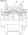
- Figure 3A illustrates another example embodiment wherein coupling 20a joins pipe elements 22a and 24a.
- the sub-surface 92a on pipe element 22a and its mating surface 112a on key 50a of coupling 20a are oriented at about 90° to the longitudinal axis 60.
- sub-surface 76a on pipe element 24a and its mating surface 104a on key 52a of coupling 20a are oriented at about 90° to the longitudinal axis 60.
- the joint is shown subjected to internal pressure induced end loads and /or axial tensile forces, as explained in detail below.
- Example pipe elements 22 and 24 when used in combination with the example coupling 20 (or coupling 20a, respectively) provide a marked improvement over prior art direct mechanical roll groove or machined groove coupling systems.
- the improved performance is due to a better axial load distribution, which, unlike prior art couplings, is not borne entirely at the first and fifth sub-surfaces 74 and 90. Rather, a portion of the axial load is borne by the sub-surfaces 74 and 90 as a result of contact between the third mating surface 106 and the third sub-surface 78 and the seventh mating surface 114 and the seventh sub-surface 94.
- These mating surfaces on the coupling and sub-surfaces on the pipe elements are oriented at an angle with respect to the longitudinal axis 60.
- the load sharing which provides improved performance is effected by the geometries of the keys 50 and 52 and the respective grooves 88 ad 54 which they engage as well as the method of assembling and using the coupling and pipe elements according to the invention.
- one method of assembly described for pipe element 24 and coupling 20 with reference to Figure 3 , comprises contacting the third sub-surface 78 of groove 54 with a portion (third mating surface 106) of the arcuate projection (key) 52, and contacting the second sub-surface 76 of groove 54 with another portion (second mating surface 104) of the arcuate projection (key) 52.
- the assembly proceeds similarly; contacting the seventh sub-surface 94 of groove 88 with a portion (seventh mating surface 114) of the arcuate projection (key) 50, and contacting the sixth sub-surface 92 of groove 88 with another portion (sixth mating surface 112) of the arcuate projection (key) 52.
- FIG. 3 An example method of using the coupling 20 having arcuate projections 50, 52 engaged with grooves 88, 54 of the pipe elements 22 and 24 is illustrated with reference to Figures 3 and 3B and comprises assembling coupling segments 26 and 28 about pipe elements 22 and 24, such that keys 50 and 52 are located within grooves 88 and 54, respectively ( Figure 3 ).
- Fasteners 44 are then installed and tightened to connect attachment members 32 and 34 and ensure that at least mating surfaces 106 and 114 come into contact with sub-surfaces 78 and 94 respectively.
- Pipe elements and their associated couplings according to the invention have demonstrated a marked improvement in the goal of realizing a greater portion of the potential strength of the pipe element when compared to prior art pipe elements and couplings.
Landscapes
- Engineering & Computer Science (AREA)
- General Engineering & Computer Science (AREA)
- Mechanical Engineering (AREA)
- Physics & Mathematics (AREA)
- Fluid Mechanics (AREA)
- Mutual Connection Of Rods And Tubes (AREA)
- Earth Drilling (AREA)
- Clamps And Clips (AREA)
- Joints With Sleeves (AREA)
- Rigid Pipes And Flexible Pipes (AREA)
- Butt Welding And Welding Of Specific Article (AREA)
- Gasket Seals (AREA)
- Flanged Joints, Insulating Joints, And Other Joints (AREA)
- Joints Allowing Movement (AREA)
- Quick-Acting Or Multi-Walled Pipe Joints (AREA)
Priority Applications (1)
| Application Number | Priority Date | Filing Date | Title |
|---|---|---|---|
| EP25223400.0A EP4691662A3 (de) | 2016-01-26 | 2017-01-19 | Rohrelement mit klemmnut |
Applications Claiming Priority (5)
| Application Number | Priority Date | Filing Date | Title |
|---|---|---|---|
| US201662287015P | 2016-01-26 | 2016-01-26 | |
| EP17744704.2A EP3408573B1 (de) | 2016-01-26 | 2017-01-19 | Kombination umfassend eine kupplung und ein rohrelement mit keilnut |
| EP21170048.9A EP3885621B1 (de) | 2016-01-26 | 2017-01-19 | Kombination umfassend eine kupplung und ein rohrelement mit keilnut |
| EP23153887.7A EP4191112B1 (de) | 2016-01-26 | 2017-01-19 | Rohrelement mit klemmnut |
| PCT/US2017/014015 WO2017132036A1 (en) | 2016-01-26 | 2017-01-19 | Pipe element having wedging groove |
Related Parent Applications (4)
| Application Number | Title | Priority Date | Filing Date |
|---|---|---|---|
| EP17744704.2A Division EP3408573B1 (de) | 2016-01-26 | 2017-01-19 | Kombination umfassend eine kupplung und ein rohrelement mit keilnut |
| EP23153887.7A Division-Into EP4191112B1 (de) | 2016-01-26 | 2017-01-19 | Rohrelement mit klemmnut |
| EP23153887.7A Division EP4191112B1 (de) | 2016-01-26 | 2017-01-19 | Rohrelement mit klemmnut |
| EP21170048.9A Division EP3885621B1 (de) | 2016-01-26 | 2017-01-19 | Kombination umfassend eine kupplung und ein rohrelement mit keilnut |
Related Child Applications (1)
| Application Number | Title | Priority Date | Filing Date |
|---|---|---|---|
| EP25223400.0A Division EP4691662A3 (de) | 2016-01-26 | 2017-01-19 | Rohrelement mit klemmnut |
Publications (2)
| Publication Number | Publication Date |
|---|---|
| EP4481255A2 true EP4481255A2 (de) | 2024-12-25 |
| EP4481255A3 EP4481255A3 (de) | 2025-06-18 |
Family
ID=59359804
Family Applications (5)
| Application Number | Title | Priority Date | Filing Date |
|---|---|---|---|
| EP17744704.2A Active EP3408573B1 (de) | 2016-01-26 | 2017-01-19 | Kombination umfassend eine kupplung und ein rohrelement mit keilnut |
| EP21170048.9A Active EP3885621B1 (de) | 2016-01-26 | 2017-01-19 | Kombination umfassend eine kupplung und ein rohrelement mit keilnut |
| EP25223400.0A Pending EP4691662A3 (de) | 2016-01-26 | 2017-01-19 | Rohrelement mit klemmnut |
| EP23153887.7A Active EP4191112B1 (de) | 2016-01-26 | 2017-01-19 | Rohrelement mit klemmnut |
| EP24210754.8A Pending EP4481255A3 (de) | 2016-01-26 | 2017-01-19 | Rohrelement mit klemmnut |
Family Applications Before (4)
| Application Number | Title | Priority Date | Filing Date |
|---|---|---|---|
| EP17744704.2A Active EP3408573B1 (de) | 2016-01-26 | 2017-01-19 | Kombination umfassend eine kupplung und ein rohrelement mit keilnut |
| EP21170048.9A Active EP3885621B1 (de) | 2016-01-26 | 2017-01-19 | Kombination umfassend eine kupplung und ein rohrelement mit keilnut |
| EP25223400.0A Pending EP4691662A3 (de) | 2016-01-26 | 2017-01-19 | Rohrelement mit klemmnut |
| EP23153887.7A Active EP4191112B1 (de) | 2016-01-26 | 2017-01-19 | Rohrelement mit klemmnut |
Country Status (24)
| Country | Link |
|---|---|
| US (3) | US10550971B2 (de) |
| EP (5) | EP3408573B1 (de) |
| JP (1) | JP6708742B2 (de) |
| KR (1) | KR102136475B1 (de) |
| CN (1) | CN108603622B (de) |
| AU (1) | AU2017211019B2 (de) |
| BR (2) | BR122021013909B1 (de) |
| CA (2) | CA3012045C (de) |
| CL (1) | CL2018001993A1 (de) |
| CO (1) | CO2018006705A2 (de) |
| DK (1) | DK3408573T3 (de) |
| ES (3) | ES2901348T3 (de) |
| MA (1) | MA42583B1 (de) |
| MX (2) | MX2018009094A (de) |
| MY (2) | MY189795A (de) |
| NZ (1) | NZ742764A (de) |
| PE (1) | PE20181286A1 (de) |
| PH (1) | PH12018501562A1 (de) |
| PL (3) | PL3408573T3 (de) |
| RU (1) | RU2693347C1 (de) |
| SA (2) | SA518391829B1 (de) |
| SG (2) | SG10202110846XA (de) |
| TW (2) | TWI669461B (de) |
| WO (1) | WO2017132036A1 (de) |
Families Citing this family (10)
| Publication number | Priority date | Publication date | Assignee | Title |
|---|---|---|---|---|
| SG11201803931WA (en) | 2015-12-28 | 2018-06-28 | Victaulic Co Of America | Adapter coupling |
| BR122021013909B1 (pt) | 2016-01-26 | 2022-04-05 | Victaulic Company | Elemento de tubo, e, métodos para montar um acoplamento tendo uma projeção arqueada com um elemento de tubo e para usar um acoplamento |
| US10859190B2 (en) | 2016-05-16 | 2020-12-08 | Victaulic Company | Sprung coupling |
| KR102173234B1 (ko) * | 2018-12-14 | 2020-11-03 | 이진숙 | 그루브 조인트용 파이프 |
| USD903835S1 (en) * | 2019-03-28 | 2020-12-01 | Victaulic Company | Coupling segment |
| USD903833S1 (en) * | 2019-03-28 | 2020-12-01 | Victaulic Company | Coupling segment |
| USD903834S1 (en) * | 2019-03-28 | 2020-12-01 | Victaulic Company | Coupling segment |
| US11781683B2 (en) | 2019-11-15 | 2023-10-10 | Victaulic Company | Shrouded coupling |
| CN111350887B (zh) * | 2020-04-13 | 2021-12-07 | 江苏金泰新减速机有限公司 | 一种工业输送工程中用的导管无缝连接装置 |
| JP7481013B2 (ja) | 2021-08-25 | 2024-05-10 | 株式会社Tozen | 管継手 |
Family Cites Families (33)
| Publication number | Priority date | Publication date | Assignee | Title |
|---|---|---|---|---|
| US3015502A (en) * | 1957-11-29 | 1962-01-02 | Victaulic Co Of America | Grooved tubing for connection with sleeve type coupling |
| US3967837A (en) * | 1974-11-04 | 1976-07-06 | Construction Forms, Inc. | High pressure coupling apparatus |
| US3995466A (en) * | 1975-09-19 | 1976-12-07 | Victaulic Company Of America | Machine for roll grooving of pipe |
| AU509587B2 (en) | 1976-01-19 | 1980-05-15 | Sekisui Kagaku Kogyo Kabushiki Kaisha | Pipe joint endless locking ring and groove arrangement |
| US4593944A (en) | 1984-01-23 | 1986-06-10 | Vetco Offshore, Inc. | Pile driving connector |
| US4640536A (en) * | 1986-02-27 | 1987-02-03 | Nelson Industries, Inc. | Tube clamp assembly |
| US4880068A (en) | 1988-11-21 | 1989-11-14 | Varel Manufacturing Company | Rotary drill bit locking mechanism |
| SU1702877A3 (ru) * | 1989-08-17 | 1991-12-30 | Г.А. Струнгис | Разъемное неподвижное уплотнительное устройство |
| SU1702897A1 (ru) * | 1989-11-03 | 1992-01-07 | Дальневосточный научно-исследовательский и проектно-технологический институт механизации и электрификации сельского хозяйства | Устройство дл обнаружени и извлечени посторонних включений из почвы |
| GB2241547A (en) | 1990-02-28 | 1991-09-04 | Senior Tift Ltd | Snap action fluid tight coupling for corrugated tube |
| US5080400A (en) * | 1990-04-30 | 1992-01-14 | Abb Vetro Gray Inc. | Double lobe tubular connector clamp |
| JPH06341577A (ja) * | 1990-12-20 | 1994-12-13 | Kurano Seisakusho:Kk | グループ式パイプ配設方法 |
| US5813705A (en) | 1996-06-18 | 1998-09-29 | Victaulic Company Of America | Snap-action pipe coupling retainer |
| JP3797534B2 (ja) * | 2000-02-18 | 2006-07-19 | 川口工業株式会社 | 管体の連結構造 |
| US6450545B1 (en) | 2001-02-21 | 2002-09-17 | Parker Hennifin Corporation | Fluid coupling plug |
| US8267432B2 (en) * | 2004-03-26 | 2012-09-18 | Victaulic Company | Coupling having angularly oriented key surfaces |
| WO2005094292A2 (en) | 2004-03-26 | 2005-10-13 | Victaulic Company Of America | Pipe coupling having wedge shaped keys |
| US7086131B2 (en) * | 2004-05-14 | 2006-08-08 | Victaulic Company | Deformable mechanical pipe coupling |
| JP4575973B2 (ja) * | 2007-10-05 | 2010-11-04 | シーケーディ株式会社 | 流体機器接続構造及び流体機器ユニット |
| US8033579B2 (en) * | 2007-10-05 | 2011-10-11 | Ckd Corporation | Fluid device connecting structure |
| WO2009102698A1 (en) * | 2008-02-12 | 2009-08-20 | Victaulic Company | Couplings having stiffening ribs and keys with oppositely disposed camming surfaces |
| US8136847B2 (en) * | 2009-05-14 | 2012-03-20 | Victaulic Company | Coupling having angularly oriented shoulder surfaces |
| US8777277B2 (en) * | 2010-12-02 | 2014-07-15 | Victaulic Company | Pipe element having shoulder, groove and bead and methods and apparatus for manufacture thereof |
| EP2750815B1 (de) * | 2011-09-02 | 2015-07-22 | Victaulic Company | Druckformungsverfahren und vorrichtung |
| US20130125373A1 (en) | 2011-11-21 | 2013-05-23 | Philip W. Bancroft | Coupling with projections having angularly oriented surface portions |
| US9500307B2 (en) | 2012-01-20 | 2016-11-22 | Mueller International, Llc | Slip-on coupling gasket |
| US9039046B2 (en) * | 2012-01-20 | 2015-05-26 | Mueller International, Llc | Coupling with tongue and groove |
| US9333548B2 (en) * | 2013-08-12 | 2016-05-10 | Victaulic Company | Method and device for forming grooves in pipe elements |
| KR101488337B1 (ko) * | 2014-05-12 | 2015-01-30 | 연우지에스티 주식회사 | 커플링 |
| US10189070B2 (en) * | 2014-08-29 | 2019-01-29 | Victaulic Company | Roller for roll forming |
| BR122021013909B1 (pt) | 2016-01-26 | 2022-04-05 | Victaulic Company | Elemento de tubo, e, métodos para montar um acoplamento tendo uma projeção arqueada com um elemento de tubo e para usar um acoplamento |
| US11378208B2 (en) | 2016-12-14 | 2022-07-05 | ASC Engineered Solutions, LLC | Pipe couplings |
| US10641419B2 (en) | 2016-12-14 | 2020-05-05 | Anvil International, Llc | Pipe coupling with closed ring |
-
2017
- 2017-01-19 BR BR122021013909-1A patent/BR122021013909B1/pt active IP Right Grant
- 2017-01-19 DK DK17744704.2T patent/DK3408573T3/da active
- 2017-01-19 MY MYPI2018000803A patent/MY189795A/en unknown
- 2017-01-19 KR KR1020187023071A patent/KR102136475B1/ko active Active
- 2017-01-19 CA CA3012045A patent/CA3012045C/en active Active
- 2017-01-19 PL PL17744704T patent/PL3408573T3/pl unknown
- 2017-01-19 US US15/409,688 patent/US10550971B2/en active Active
- 2017-01-19 SG SG10202110846XA patent/SG10202110846XA/en unknown
- 2017-01-19 EP EP17744704.2A patent/EP3408573B1/de active Active
- 2017-01-19 CN CN201780008196.0A patent/CN108603622B/zh active Active
- 2017-01-19 BR BR112018015033-9A patent/BR112018015033B1/pt active IP Right Grant
- 2017-01-19 EP EP21170048.9A patent/EP3885621B1/de active Active
- 2017-01-19 WO PCT/US2017/014015 patent/WO2017132036A1/en not_active Ceased
- 2017-01-19 NZ NZ74276417A patent/NZ742764A/en unknown
- 2017-01-19 ES ES17744704T patent/ES2901348T3/es active Active
- 2017-01-19 ES ES21170048T patent/ES2951087T3/es active Active
- 2017-01-19 CA CA3081928A patent/CA3081928C/en active Active
- 2017-01-19 PL PL23153887.7T patent/PL4191112T3/pl unknown
- 2017-01-19 MY MYPI2021003715A patent/MY210549A/en unknown
- 2017-01-19 EP EP25223400.0A patent/EP4691662A3/de active Pending
- 2017-01-19 EP EP23153887.7A patent/EP4191112B1/de active Active
- 2017-01-19 SG SG11201804215VA patent/SG11201804215VA/en unknown
- 2017-01-19 PL PL21170048.9T patent/PL3885621T3/pl unknown
- 2017-01-19 MX MX2018009094A patent/MX2018009094A/es unknown
- 2017-01-19 RU RU2018130671A patent/RU2693347C1/ru active
- 2017-01-19 EP EP24210754.8A patent/EP4481255A3/de active Pending
- 2017-01-19 ES ES23153887T patent/ES3008464T3/es active Active
- 2017-01-19 JP JP2018535848A patent/JP6708742B2/ja active Active
- 2017-01-19 AU AU2017211019A patent/AU2017211019B2/en active Active
- 2017-01-19 PE PE2018001295A patent/PE20181286A1/es unknown
- 2017-01-19 MA MA42583A patent/MA42583B1/fr unknown
- 2017-01-25 TW TW106102779A patent/TWI669461B/zh active
- 2017-01-25 TW TW108125844A patent/TWI693359B/zh active
-
2018
- 2018-06-18 SA SA518391829A patent/SA518391829B1/ar unknown
- 2018-06-18 SA SA521421727A patent/SA521421727B1/ar unknown
- 2018-06-27 CO CONC2018/0006705A patent/CO2018006705A2/es unknown
- 2018-07-20 PH PH12018501562A patent/PH12018501562A1/en unknown
- 2018-07-23 CL CL2018001993A patent/CL2018001993A1/es unknown
- 2018-07-25 MX MX2022009992A patent/MX2022009992A/es unknown
-
2019
- 2019-11-25 US US16/693,973 patent/US11725759B2/en active Active
-
2023
- 2023-07-21 US US18/356,733 patent/US20230358349A1/en active Pending
Also Published As
Similar Documents
| Publication | Publication Date | Title |
|---|---|---|
| US20230358349A1 (en) | Pipe Element Having Wedging Groove | |
| US12129941B2 (en) | Coupling having arcuate stiffness ribs | |
| US20080029971A1 (en) | Seal ring and method | |
| US20180100609A1 (en) | Coupling and Seal | |
| GB2550960A (en) | Pipe connecting apparatus | |
| HK1256126B (en) | Pipe element having wedging groove | |
| US9765927B2 (en) | Flange fitting | |
| EP0455464A2 (de) | Rohrkupplung | |
| WO2018100022A1 (en) | Flange coupling |
Legal Events
| Date | Code | Title | Description |
|---|---|---|---|
| PUAI | Public reference made under article 153(3) epc to a published international application that has entered the european phase |
Free format text: ORIGINAL CODE: 0009012 |
|
| STAA | Information on the status of an ep patent application or granted ep patent |
Free format text: STATUS: THE APPLICATION HAS BEEN PUBLISHED |
|
| AC | Divisional application: reference to earlier application |
Ref document number: 3408573 Country of ref document: EP Kind code of ref document: P Ref document number: 3885621 Country of ref document: EP Kind code of ref document: P Ref document number: 4191112 Country of ref document: EP Kind code of ref document: P |
|
| AK | Designated contracting states |
Kind code of ref document: A2 Designated state(s): AL AT BE BG CH CY CZ DE DK EE ES FI FR GB GR HR HU IE IS IT LI LT LU LV MC MK MT NL NO PL PT RO RS SE SI SK SM TR |
|
| RIC1 | Information provided on ipc code assigned before grant |
Ipc: B21D 17/04 20060101ALI20250204BHEP Ipc: F16L 17/04 20060101AFI20250204BHEP |
|
| PUAL | Search report despatched |
Free format text: ORIGINAL CODE: 0009013 |
|
| AK | Designated contracting states |
Kind code of ref document: A3 Designated state(s): AL AT BE BG CH CY CZ DE DK EE ES FI FR GB GR HR HU IE IS IT LI LT LU LV MC MK MT NL NO PL PT RO RS SE SI SK SM TR |
|
| RIC1 | Information provided on ipc code assigned before grant |
Ipc: B21D 17/04 20060101ALI20250513BHEP Ipc: F16L 17/04 20060101AFI20250513BHEP |
|
| STAA | Information on the status of an ep patent application or granted ep patent |
Free format text: STATUS: REQUEST FOR EXAMINATION WAS MADE |
|
| 17P | Request for examination filed |
Effective date: 20251216 |