EP4481268A1 - Dispositif optique pour véhicule automobile et procédé d'assemblage associé - Google Patents
Dispositif optique pour véhicule automobile et procédé d'assemblage associé Download PDFInfo
- Publication number
- EP4481268A1 EP4481268A1 EP23180690.2A EP23180690A EP4481268A1 EP 4481268 A1 EP4481268 A1 EP 4481268A1 EP 23180690 A EP23180690 A EP 23180690A EP 4481268 A1 EP4481268 A1 EP 4481268A1
- Authority
- EP
- European Patent Office
- Prior art keywords
- light
- cover
- light guide
- optical device
- inner cover
- Prior art date
- Legal status (The legal status is an assumption and is not a legal conclusion. Google has not performed a legal analysis and makes no representation as to the accuracy of the status listed.)
- Withdrawn
Links
Images


Classifications
-
- F—MECHANICAL ENGINEERING; LIGHTING; HEATING; WEAPONS; BLASTING
- F21—LIGHTING
- F21S—NON-PORTABLE LIGHTING DEVICES; SYSTEMS THEREOF; VEHICLE LIGHTING DEVICES SPECIALLY ADAPTED FOR VEHICLE EXTERIORS
- F21S43/00—Signalling devices specially adapted for vehicle exteriors, e.g. brake lamps, direction indicator lights or reversing lights
- F21S43/10—Signalling devices specially adapted for vehicle exteriors, e.g. brake lamps, direction indicator lights or reversing lights characterised by the light source
- F21S43/13—Signalling devices specially adapted for vehicle exteriors, e.g. brake lamps, direction indicator lights or reversing lights characterised by the light source characterised by the type of light source
- F21S43/14—Light emitting diodes [LED]
-
- F—MECHANICAL ENGINEERING; LIGHTING; HEATING; WEAPONS; BLASTING
- F21—LIGHTING
- F21S—NON-PORTABLE LIGHTING DEVICES; SYSTEMS THEREOF; VEHICLE LIGHTING DEVICES SPECIALLY ADAPTED FOR VEHICLE EXTERIORS
- F21S43/00—Signalling devices specially adapted for vehicle exteriors, e.g. brake lamps, direction indicator lights or reversing lights
- F21S43/20—Signalling devices specially adapted for vehicle exteriors, e.g. brake lamps, direction indicator lights or reversing lights characterised by refractors, transparent cover plates, light guides or filters
- F21S43/235—Light guides
- F21S43/236—Light guides characterised by the shape of the light guide
- F21S43/237—Light guides characterised by the shape of the light guide rod-shaped
-
- F—MECHANICAL ENGINEERING; LIGHTING; HEATING; WEAPONS; BLASTING
- F21—LIGHTING
- F21S—NON-PORTABLE LIGHTING DEVICES; SYSTEMS THEREOF; VEHICLE LIGHTING DEVICES SPECIALLY ADAPTED FOR VEHICLE EXTERIORS
- F21S43/00—Signalling devices specially adapted for vehicle exteriors, e.g. brake lamps, direction indicator lights or reversing lights
- F21S43/20—Signalling devices specially adapted for vehicle exteriors, e.g. brake lamps, direction indicator lights or reversing lights characterised by refractors, transparent cover plates, light guides or filters
- F21S43/235—Light guides
- F21S43/242—Light guides characterised by the emission area
- F21S43/245—Light guides characterised by the emission area emitting light from one or more of its major surfaces
-
- F—MECHANICAL ENGINEERING; LIGHTING; HEATING; WEAPONS; BLASTING
- F21—LIGHTING
- F21S—NON-PORTABLE LIGHTING DEVICES; SYSTEMS THEREOF; VEHICLE LIGHTING DEVICES SPECIALLY ADAPTED FOR VEHICLE EXTERIORS
- F21S43/00—Signalling devices specially adapted for vehicle exteriors, e.g. brake lamps, direction indicator lights or reversing lights
- F21S43/20—Signalling devices specially adapted for vehicle exteriors, e.g. brake lamps, direction indicator lights or reversing lights characterised by refractors, transparent cover plates, light guides or filters
- F21S43/235—Light guides
- F21S43/247—Light guides with a single light source being coupled into the light guide
-
- F—MECHANICAL ENGINEERING; LIGHTING; HEATING; WEAPONS; BLASTING
- F21—LIGHTING
- F21S—NON-PORTABLE LIGHTING DEVICES; SYSTEMS THEREOF; VEHICLE LIGHTING DEVICES SPECIALLY ADAPTED FOR VEHICLE EXTERIORS
- F21S43/00—Signalling devices specially adapted for vehicle exteriors, e.g. brake lamps, direction indicator lights or reversing lights
- F21S43/20—Signalling devices specially adapted for vehicle exteriors, e.g. brake lamps, direction indicator lights or reversing lights characterised by refractors, transparent cover plates, light guides or filters
- F21S43/235—Light guides
- F21S43/253—Two or more juxtaposed light guides
-
- F—MECHANICAL ENGINEERING; LIGHTING; HEATING; WEAPONS; BLASTING
- F21—LIGHTING
- F21S—NON-PORTABLE LIGHTING DEVICES; SYSTEMS THEREOF; VEHICLE LIGHTING DEVICES SPECIALLY ADAPTED FOR VEHICLE EXTERIORS
- F21S43/00—Signalling devices specially adapted for vehicle exteriors, e.g. brake lamps, direction indicator lights or reversing lights
- F21S43/20—Signalling devices specially adapted for vehicle exteriors, e.g. brake lamps, direction indicator lights or reversing lights characterised by refractors, transparent cover plates, light guides or filters
- F21S43/27—Attachment thereof
-
- F—MECHANICAL ENGINEERING; LIGHTING; HEATING; WEAPONS; BLASTING
- F21—LIGHTING
- F21S—NON-PORTABLE LIGHTING DEVICES; SYSTEMS THEREOF; VEHICLE LIGHTING DEVICES SPECIALLY ADAPTED FOR VEHICLE EXTERIORS
- F21S43/00—Signalling devices specially adapted for vehicle exteriors, e.g. brake lamps, direction indicator lights or reversing lights
- F21S43/50—Signalling devices specially adapted for vehicle exteriors, e.g. brake lamps, direction indicator lights or reversing lights characterised by aesthetic components not otherwise provided for, e.g. decorative trim, partition walls or covers
-
- F—MECHANICAL ENGINEERING; LIGHTING; HEATING; WEAPONS; BLASTING
- F21—LIGHTING
- F21S—NON-PORTABLE LIGHTING DEVICES; SYSTEMS THEREOF; VEHICLE LIGHTING DEVICES SPECIALLY ADAPTED FOR VEHICLE EXTERIORS
- F21S43/00—Signalling devices specially adapted for vehicle exteriors, e.g. brake lamps, direction indicator lights or reversing lights
- F21S43/50—Signalling devices specially adapted for vehicle exteriors, e.g. brake lamps, direction indicator lights or reversing lights characterised by aesthetic components not otherwise provided for, e.g. decorative trim, partition walls or covers
- F21S43/51—Attachment thereof
Definitions
- the present invention relates to an optical device for an automotive vehicle, and more particularly to an optical device having a double cover assembly to cover a part of the optical device.
- Optical devices are used in automobiles and the like, for lighting the path ahead and also for providing signaling functions. These lighting functions include low beam light, high beam lights, turn indicator, parking/position lamp, tail/ stop lamp, day running lights (DRL), fog lamp and/ or signature lamp.
- Most of the modern optical devices use light guides that are attached facing one or more light sources. The light produced by these light sources enters the light guide through a light entry portion and is propagated through the light guide by multiple total internal reflection.
- different light guides each associated with a specific function may be provided, for example individual light guides associated with an amber light source and a white light source for turn indicator and DRL function respectively may be provided.
- the optical devices using light guides are known to be affected by light leakage issues.
- the leakage may affect the optical efficiency of the optical device further affecting the lighting function as well. It is paramount in optical devices disclosed above (specifically having multiple light guides) that the light from one light guide does not leak to the other light guide. Also any undesired leakage of light from the light guide towards outside needs to be prevented.
- the leakage may affect the lighting functionality and may create a safety issue due to light mixing, especially light color mixing and undesired exposure of the light guide. Further, the light leakage may affect the visual styling of the vehicle headlamp which may be perceived negatively by the user.
- Some optical devices may be designed such that the light guides need to cross each other in a physical plane. This crossing of light guides is needed in order to fulfill the requirements pertaining to light guide curvature and also to meet regulation. In such optical devices the light leakage is a huge issue and may aggravate the above disclosed issues.
- some optical modules are provided with a cover that are configured to cover a portion of the light guide.
- These covers are usually fixed to the housing or a mask by means of clipping structures such as press clips or snap fit clips.
- clipping structures such as press clips or snap fit clips.
- the cover having clipping structures may involve assembly constraints and may not be able to properly fit to the housing and may not be able to arrest the movement of the cover during harsh vehicle operation conditions leading to failure.
- An object of the present invention is to solve the disadvantages described above of known optical devices.
- the object of the present invention is to provide an optical device that can prevent light leakage between the light guides and from light guides towards outside of the optical device.
- an optical device for an automotive vehicle comprises: at least one light source configured to produce a light beam, at least one light guide configured to propagate said light beam.
- the at least one light guide includes a light entry portion arranged facing the at least one light source to receive said light beam.
- the optical guide comprises at least one support structure configured to support the at least one light guide, and at least one double cover assembly mounted on at least one support structure, configured to cover the light entry portion of the at least one light guide.
- An inner cover of the at least one double cover assembly and the at least one support structure may create a hinge in an assembled state, further, the hinge is configured to rotatably secure the at least one double cover assembly and the at least one support structure around a hinge axis.
- the double cover assembly is arranged over the light entry portions of the light guides thus masking light leakage from the said face of the light guide from being visible. Further, an outer cover of the double cover assembly covers at least a portion of a second light guide thus preventing leakage of the light from the second light guide towards outside.
- the at least one double cover assembly comprises an inner cover hingedly mounted on the at least one support structure such that the inner cover can be rotated to cover the light entry portion of the at least one light guide.
- the at least one double cover assembly further comprises an outer cover pivotally connected to the inner cover at a predetermined edge to cover at least a portion of the second light guide.
- the outer cover is configured to be secured to the inner cover by a locking mechanism.
- the outer cover is configured to be integrally formed with the inner cover and a connecting portion is formed between them to allow the rotation of the outer cover relative to the inner cover.
- the thickness of the connecting portion is reduced or lower or less than the thickness of the inner cover and the outer cover, to provide flexibility to said connection portion.
- the connecting portion is made flexible, the outer cover can be rotated with respect to the inner cover to prevent light leakage from at least one light guide placed between the inner cover and the outer cover, towards the outside.
- the connecting portion is configured to be formed continuously along the edges of the outer cover and the inner cover.
- the connecting portion is configured to be formed intermittently along the edges of the outer cover and the inner cover, to allow the rotation of the outer cover relative to the inner cover.
- the connecting portion comprises multiple bridge sections having reduced or lower or less thickness, compared to the thickness of the inner and outer cover.
- the connecting portion is made flexible to allow relative rotation between the outer cover and the inner cover.
- flexible means that the connecting portion is adapted to be folded, between an open configuration and a closed configuration of the outer cover, without being damaged or broken. In the open configuration of the outer cover, the outer cover is pivoted away from the inner cover.
- the outer cover is configured to be pivotally connected to the inner cover through hinges or straps.
- any suitable pivot joint can be used to connect the outer cover with the inner cover.
- the outer cover is configured to be pivotally connected to a top edge of the inner cover.
- the outer cover is configured to be pivotally connected to a bottom edge of the inner cover.
- the outer cover is configured to be rotated over the second light guide and secured with the inner cover by a locking mechanism.
- the locking mechanism comprises any of a press-fit mechanism or a snap-fit mechanism or hooks or glue tape or any similar connection means.
- the optical device comprises at least two light guides and at least two light sources, and further, each of the light guides is arranged facing respectively one of the at least two light sources.
- Each of the light guides along with the respective light sources may enable using different lighting functions such as turn indicator and day running light functions.
- the optical device may include a single light guide arranged facing a single or plurality of light sources. In said configuration, the optical device may be configured to perform a single lighting function or different lighting functions.
- a method of assembling at least one double cover assembly, according to the present invention, on at least one support structure of an optical device comprises the steps of mounting a first light guide on the at least one support structure of the optical device, further, a light entry portion of the first light guide is arranged facing a light source.
- the assembly process further comprises the step of mounting at least one double cover assembly on said support structure wherein an inner cover of the double cover assembly is configured to be hingedly mounted on the at least one support structure to cover the light entry portion of the at least one light guide.
- the assembly process further comprises a step of mounting a second light guide over the inner cover of the at least one double cover assembly.
- the second light guide assembled over the inner cover enables the light guides to be placed on the opposite sides of the inner cover, thus preventing light leakage between the two light guides.
- the assembly process further comprises a step of rotating an outer cover of the at least one double cover assembly to cover the light entry portion of the second light guide, thus preventing light leakage from the light entry portion of the second light guide towards outside.
- the assembly process further comprises a step of securing the outer cover with the inner cover by a locking mechanism.
- the locking mechanism can be any of a clipping structure, a press-fit mechanism, a snap-fit assembly, hooks or glue tape.
- the assembly process allows an easy and secure assembly of the double cover assembly on the support structure and further prevents light leakage from the light guides.
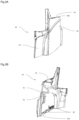
- FIG 1 shows an optical device 100 for an automotive vehicle according to an embodiment of the present invention.
- the optical device 100 of the present invention comprises at least one light source 10 (as seen in Figure 2 ) configured to produce a light beam.
- the light beam produced by the light sources 10 may be used for various lighting functions such as low beam light, high beam lights, turn indicator, parking/position lamp, tail/ stop lamp, day running lights (DRL), fog lamp and/ or signature lamp.
- the light sources 10 may be of amber and white color respectively, to achieve the above said functions.
- the light sources 10 may be of red color to achieve stop lamp or tail lamp function, further, the light sources 10 may be adapted to achieve fog lamp function as well.
- the optical device 100 may comprise at least one light guide 20 configured to propagate said light beam.
- the at least one light guide 20 includes a light entry portion 22 arranged facing the at least one light source 10 to receive said light beam.
- the light beam that enters the at least one light guide 20 through the light entry portion 22 may be propagated towards a light exit portion (not shown) of the light guide 20 by means of multiple total internal reflection.
- the light beam exiting from said exit portion may be viewable from outside the optical device 100 to carry out the desired lighting function.
- Light guides are usually supported by a light guide support structure which may be further supported on a housing of the optical device.
- the support structure may also function as a mask that may be configured to mask other components of the optical device.
- the optical device 100 further comprises at least one support structure 30 configured to support the at least one light guide 20.
- the support structure 30 may allow supporting the at least one light guide 20 with respect to the light sources 10.
- the light guide 20 is arranged such that optimal distance is maintained between the light sources 10 and the at least one light guide 20. The optimal distance signifies the best possible position of the light guide with respect to the light sources so as to allow optimized or maximized amount of light beam produced by the light source 10 transmitted through the entry portion 22.
- the optical device 100 may comprise at least one double cover assembly 40 that is mounted on the at least one support structure 30 and may be configured to cover the light entry portion 22 of the at least one light guide 20.
- the at least one double cover assembly 40 is a physical structure or part that may be assembled over the specific portion of the light guide 20 so that the light guide may not be visible from outside the optical device 100.
- the at least one double cover assembly 40 comprises an inner cover 42 to be hingedly mounted on the at least one support structure 30.
- the at least one double cover assembly 40 further comprises an outer cover 44 pivotally connected to the inner cover 42.
- a locking mechanism 60 is provided to secure the free end of the outer cover 44 with the inner cover 42.
- the light guides 20, 20' are placed on the opposite sides of the inner cover 42, thus preventing light leakage between a first light guide 20 and a second light guide 20'.
- the outer cover 44 when closed, masks at least a portion of the second light guide 20' to prevent light leakage from the light entry portion 22' of the second light guide 20' towards outside.
- the outer cover 44 is secured in its closed state, to the inner cover 42 by a press-fit mechanism or a snap-fit mechanism or hooks or glue tape or any similar connection means.
- the outer cover 44 and the inner cover 42 are integrally formed as a single part.
- a continuous connecting portion 43 may be formed between the inner cover 42 and the outer cover 44 to allow the pivoting motion of the outer cover 44.
- intermittent bridges of the connecting portions may be formed between the inner cover 42 and the outer cover 44.
- the thickness of the connecting portion 43 is lower or less than the thickness of the inner cover 42 and the outer cover 44 allowing the connecting portion 43 to be flexible. The flexibility of the connecting portion 43 allows the outer cover 44 to be rotated with respect to the inner cover 42 to cover the light entry portion 22' of the second light guide 20' positioned between the inner cover 42 and the outer cover 44.
- the outer cover 44 may be pivotally connected to a top edge 422 or a bottom edge 424 of the inner cover 42.
- the top and bottom must be understood as in the normal mounting orientation of the double cover assembly 40 on the vehicle.
- the double cover assembly is made from plastic or any suitable material.
- the outer cover 44 and the inner cover 42 may be pivotally connected through hinges or straps.
- the optical device 100 comprises at least a first light guide 20, and a second light guide 20', configured to propagate light from at least two light sources 10.
- the two light guides 20, 20' may be associated with two light sources 10 such as amber color light source and white color light source for enabling turn indicator function and day running light function respectively.
- the first light guide 20 is associated with an amber color light source
- the second light guide 20' is associated with an white color light source, or opposite.
- both light guides may be associated respectively with at least one amber color light source and one white color light source.
- the at least one double cover assembly 40 comprises an inner cover 42 hingedly mounted on the support structure 30 and an outer cover 44 pivotally connected to the inner cover 42 through a connecting portion 43.
- the first light guide 20 and the second light guide 20' are assembled on opposite sides of the inner cover 42 and the outer cover 44 is closed to cover at least some portion of the second light guide 20'.
- the light guides 20, 20' are on opposite sides of the inner cover 42, the light from the first light guide 20 does not leak into the second light guide 20', and the light from the second light guide 20' does not leak into the first light guide 20.
- the outer cover 44 is closed to cover at least some portion of the second light guide 20', the light from the entry portion 22' of the second light guide 20' does not leak to the outside.
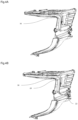
- FIG. 4A illustrates at least one support structure 30 at the initial step of assembly.
- the assembly process comprises the steps of providing a first light guide 20 on the at least one support structure 30 of the optical device 100.
- the first light guide 20 is provided such that a light entry portion 22 of the first light guide 20 is arranged facing a light source 10.
- the distance between the first light guide 20 and the light source 10 may be maintained such that an optimized or maximized amount of light beam produced by the light source 10 is transmitted through the entry portion 22.
- At least one double cover assembly 40 may be provided on said support structure 30 such that an inner cover 42 of the double cover assembly 40 covers the light entry portion 22 of the first light guide 20.
- the inner cover 42 of the at least one double cover assembly 40 may be configured to form a hinge with the at least one support structure 30.
- an outer cover 44 of the double cover assembly 40 is in open configuration, as shown in Figure 4C , wherein the free end of the outer cover 44 is away from the inner cover 42.
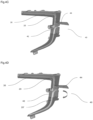
- the assembly process comprises a step of providing a second light guide 20' over the inner cover 42 of the at least one double cover assembly 40.
- the second light guide 20' may be provided on the opposite side of the inner cover 42 as compared to the first light guide 20. Similar to the first light guide 20, light entry portion 22' of the second light guide 20' is arranged facing another light source 10.
- the inner cover 42 of the at least one double cover assembly 40 may be secured on the support 30 using clipping structures that are configured to mate with locking structures of the at least one support structure 30.
- the outer cover 44 of the double cover assembly 40 is rotated from its open configuration to closed configuration, about a flexible connecting portion 43 to cover the light entry portion 22' of the second light guide 20'. Further, the outer cover 44 is secured to the inner cover 42 by locking a free end of the outer cover 44 on the inner cover 42 by a locking mechanism 60.
- Reference Number Description 10 10 light source 20 light guide 22 light entry portion 30 support structure 40 double cover assembly 42 Inner cover 43 connecting portion 44 outer cover 60 locking mechanism 100 optical device 422 top edge of the inner cover 424 bottom edge of the inner cover
Landscapes
- Engineering & Computer Science (AREA)
- General Engineering & Computer Science (AREA)
- Physics & Mathematics (AREA)
- Microelectronics & Electronic Packaging (AREA)
- Optics & Photonics (AREA)
- Non-Portable Lighting Devices Or Systems Thereof (AREA)
Priority Applications (1)
| Application Number | Priority Date | Filing Date | Title |
|---|---|---|---|
| EP23180690.2A EP4481268A1 (fr) | 2023-06-21 | 2023-06-21 | Dispositif optique pour véhicule automobile et procédé d'assemblage associé |
Applications Claiming Priority (1)
| Application Number | Priority Date | Filing Date | Title |
|---|---|---|---|
| EP23180690.2A EP4481268A1 (fr) | 2023-06-21 | 2023-06-21 | Dispositif optique pour véhicule automobile et procédé d'assemblage associé |
Publications (1)
| Publication Number | Publication Date |
|---|---|
| EP4481268A1 true EP4481268A1 (fr) | 2024-12-25 |
Family
ID=86942096
Family Applications (1)
| Application Number | Title | Priority Date | Filing Date |
|---|---|---|---|
| EP23180690.2A Withdrawn EP4481268A1 (fr) | 2023-06-21 | 2023-06-21 | Dispositif optique pour véhicule automobile et procédé d'assemblage associé |
Country Status (1)
| Country | Link |
|---|---|
| EP (1) | EP4481268A1 (fr) |
Citations (6)
| Publication number | Priority date | Publication date | Assignee | Title |
|---|---|---|---|---|
| CN202501405U (zh) * | 2011-11-21 | 2012-10-24 | 光阳工业股份有限公司 | 导光条固定装置、导光模组及灯组 |
| US8702291B2 (en) * | 2010-01-04 | 2014-04-22 | John Stephan | Illuminatable apparatus and method of manufacturing same |
| CN209458847U (zh) * | 2019-04-16 | 2019-10-01 | 华域视觉科技(上海)有限公司 | 一种光导护套结构及车灯 |
| US20190309923A1 (en) * | 2016-12-21 | 2019-10-10 | HELLA GmbH & Co. KGaA | Lighting device for vehicles |
| CN211502624U (zh) * | 2020-02-20 | 2020-09-15 | 常州星宇车灯股份有限公司 | 一种带光导的防漏光灯具结构 |
| US10906457B2 (en) * | 2016-02-04 | 2021-02-02 | Ts Tech Co., Ltd. | Lighting device |
-
2023
- 2023-06-21 EP EP23180690.2A patent/EP4481268A1/fr not_active Withdrawn
Patent Citations (6)
| Publication number | Priority date | Publication date | Assignee | Title |
|---|---|---|---|---|
| US8702291B2 (en) * | 2010-01-04 | 2014-04-22 | John Stephan | Illuminatable apparatus and method of manufacturing same |
| CN202501405U (zh) * | 2011-11-21 | 2012-10-24 | 光阳工业股份有限公司 | 导光条固定装置、导光模组及灯组 |
| US10906457B2 (en) * | 2016-02-04 | 2021-02-02 | Ts Tech Co., Ltd. | Lighting device |
| US20190309923A1 (en) * | 2016-12-21 | 2019-10-10 | HELLA GmbH & Co. KGaA | Lighting device for vehicles |
| CN209458847U (zh) * | 2019-04-16 | 2019-10-01 | 华域视觉科技(上海)有限公司 | 一种光导护套结构及车灯 |
| CN211502624U (zh) * | 2020-02-20 | 2020-09-15 | 常州星宇车灯股份有限公司 | 一种带光导的防漏光灯具结构 |
Similar Documents
| Publication | Publication Date | Title |
|---|---|---|
| US5884997A (en) | Light bar | |
| CN101486367B (zh) | 跨骑式车辆 | |
| NL8403354A (nl) | Modulaire staaflichteenheid met laag profiel. | |
| JP2010537883A (ja) | リアビューミラー | |
| FR2872257B1 (fr) | Module d'eclairage pour vehicule automobile et projecteur comportant un tel module | |
| JP4116715B2 (ja) | 自動車用ヘッドランプ | |
| US4754375A (en) | Combination reflector for wide angle warning light | |
| US6685325B1 (en) | Vehicle side mirror assembly with integral illumination and signal lighting | |
| CN115042696A (zh) | 一种分体式前灯组的安装结构及车辆 | |
| JPH08216773A (ja) | 車両のフロント部に配置された照明装置 | |
| US7527404B2 (en) | Lighting and/or signalling apparatus for a motor vehicle | |
| JPH01175539A (ja) | 自動車用ハイマウンテッドストップランプ | |
| JP4388297B2 (ja) | 農作業機のフロントグリル構造 | |
| JP3235039B2 (ja) | ランプ構造 | |
| EP4198380B1 (fr) | Dispositif optique pour un phare de véhicule automobile | |
| CN100439791C (zh) | 车辆用灯具 | |
| CN222503610U (zh) | 大灯组件及车辆 | |
| JP3257166B2 (ja) | ランプ構造 | |
| JPS6335860Y2 (fr) | ||
| JPH0346402Y2 (fr) | ||
| CN219693081U (zh) | 一种车灯光学模组总成及车灯 | |
| EP4653759A1 (fr) | Lampe de véhicule | |
| CN216158964U (zh) | 机动车辆前照灯及机动车辆 | |
| JP3915141B2 (ja) | 車両用灯具 | |
| JP2579622Y2 (ja) | 車輌用灯具 |
Legal Events
| Date | Code | Title | Description |
|---|---|---|---|
| PUAI | Public reference made under article 153(3) epc to a published international application that has entered the european phase |
Free format text: ORIGINAL CODE: 0009012 |
|
| STAA | Information on the status of an ep patent application or granted ep patent |
Free format text: STATUS: THE APPLICATION HAS BEEN PUBLISHED |
|
| AK | Designated contracting states |
Kind code of ref document: A1 Designated state(s): AL AT BE BG CH CY CZ DE DK EE ES FI FR GB GR HR HU IE IS IT LI LT LU LV MC ME MK MT NL NO PL PT RO RS SE SI SK SM TR |
|
| STAA | Information on the status of an ep patent application or granted ep patent |
Free format text: STATUS: THE APPLICATION IS DEEMED TO BE WITHDRAWN |
|
| 18D | Application deemed to be withdrawn |
Effective date: 20250626 |