EP4481652A1 - Procédé de couplage - Google Patents
Procédé de couplage Download PDFInfo
- Publication number
- EP4481652A1 EP4481652A1 EP24179762.0A EP24179762A EP4481652A1 EP 4481652 A1 EP4481652 A1 EP 4481652A1 EP 24179762 A EP24179762 A EP 24179762A EP 4481652 A1 EP4481652 A1 EP 4481652A1
- Authority
- EP
- European Patent Office
- Prior art keywords
- transponder
- event
- criterion
- coupling
- identifier
- Prior art date
- Legal status (The legal status is an assumption and is not a legal conclusion. Google has not performed a legal analysis and makes no representation as to the accuracy of the status listed.)
- Pending
Links
Images



Classifications
-
- G—PHYSICS
- G06—COMPUTING OR CALCULATING; COUNTING
- G06Q—INFORMATION AND COMMUNICATION TECHNOLOGY [ICT] SPECIALLY ADAPTED FOR ADMINISTRATIVE, COMMERCIAL, FINANCIAL, MANAGERIAL OR SUPERVISORY PURPOSES; SYSTEMS OR METHODS SPECIALLY ADAPTED FOR ADMINISTRATIVE, COMMERCIAL, FINANCIAL, MANAGERIAL OR SUPERVISORY PURPOSES, NOT OTHERWISE PROVIDED FOR
- G06Q10/00—Administration; Management
- G06Q10/08—Logistics, e.g. warehousing, loading or distribution; Inventory or stock management
- G06Q10/087—Inventory or stock management, e.g. order filling, procurement or balancing against orders
-
- H—ELECTRICITY
- H04—ELECTRIC COMMUNICATION TECHNIQUE
- H04W—WIRELESS COMMUNICATION NETWORKS
- H04W4/00—Services specially adapted for wireless communication networks; Facilities therefor
- H04W4/02—Services making use of location information
- H04W4/029—Location-based management or tracking services
-
- H—ELECTRICITY
- H04—ELECTRIC COMMUNICATION TECHNIQUE
- H04W—WIRELESS COMMUNICATION NETWORKS
- H04W4/00—Services specially adapted for wireless communication networks; Facilities therefor
- H04W4/80—Services using short range communication, e.g. near-field communication [NFC], radio-frequency identification [RFID] or low energy communication
-
- H—ELECTRICITY
- H04—ELECTRIC COMMUNICATION TECHNIQUE
- H04W—WIRELESS COMMUNICATION NETWORKS
- H04W4/00—Services specially adapted for wireless communication networks; Facilities therefor
- H04W4/30—Services specially adapted for particular environments, situations or purposes
- H04W4/38—Services specially adapted for particular environments, situations or purposes for collecting sensor information
Definitions
- the invention relates to a coupling method, in particular a computer-implemented coupling method, for coupling a digital object to a transponder. Furthermore, the invention relates to a computer program, a data processing device, in particular configured to execute the computer program, a positioning system and a use.
- positioning systems are used to track objects and/or people.
- Real-time positioning systems are particularly well known for automatically identifying and tracking the location of objects or people in real time.
- RTLS Real-time positioning systems
- a positioning system is implemented in a closed or enclosed area, such as a building or a building arrangement with, for example, a plurality of distributed and interconnected building parts.
- positioning in a positioning system can be based on two different principles, which are illustrated in the Figures 1a (self-locating principle) and 1b (external locating principle) are shown schematically.
- the Figure 1 a positioning system 198 for self-locating with at least one transmitter 196 (usually a plurality of transmitters) and at least one (central) data processing device 190 in order to locate at least one object 188.
- the moving object 188 to be located or a receiver of the object 188 receives signals with different signal strengths from the permanently mounted transmitters 196 or transponders, the positions of which are known in the positioning system and in particular in the object. From these data, the object 188 can determine its own position and in particular transmit it to the at least one data processing device 190.
- the Figure 1b shows a positioning system 100 for external positioning with at least one receiving device 104 (as a rule, a plurality of (fixed-mounted) receiving devices 104 can be provided) and a (central) data processing device 102, which is communicatively connected to the at least one receiving device 104. Furthermore, in the Figure 1b to recognize that a wireless transponder 106 is attached to the object 188 to be tracked (or a user). The fixed reference points in the form of the receiving devices 104 are set up to receive the transponder signals (e.g. periodically transmitted) of the at least one transponder 106.
- a respective receiving device 104 can be set up to transmit at least the data content of the at least one received transponder signal to the data processing device 102, in particular of a background system.
- the data processing device 102 can be set up to evaluate the received data content. This makes it possible to determine the position of the object in the data processing device 102 and/or to determine, for example, that a transponder 106 or the corresponding object 188 has left or entered a defined sub-area of the closed area, in particular at a definable point in time. This can lead to the generation and storage of a corresponding event in the data processing device of the background system.
- a positioning system especially in the form of an RTLS, is usually based on some form of radio frequency (RF) communication technology, such as UWB (Ultra-Wideband), RFID (Radio Frequency Identification), WiFi or Bluetooth (especially Bluetooth LE).
- RF radio frequency
- UWB Ultra-Wideband
- RFID Radio Frequency Identification
- WiFi Wireless Fidelity
- Bluetooth especially Bluetooth LE
- optical e.g. infrared
- acoustic e.g. ultrasonic
- Objects and transponders therefore require a digital representation in the background system, in particular in the form of a coupling data set, containing, for example, an object identifier of the object and a transponder identifier of the transponder. Coupling or linking is carried out in particular by so-called pairing, in which a transponder identifier and an object identifier can be linked to one another in the coupling data set in the background system.
- a transponder in order to carry out the coupling or pairing, is first manually selected by a user, in particular from a large number of available transponders.
- the transponder identifier of the selected transponder is then recorded using a reader or an input device.
- the user also selects an object to be linked to the transponder.
- the object identifier can be recorded using a reader or input device or a digital interface.
- the identifiers mentioned are then stored in the (common) coupling data set and the transponder is attached to the object.
- a previously described tracking system can be used in a production system for producing at least one product from at least one component.
- a production system there are usually a large number of physical objects (e.g. transport devices in the form of load carriers, components, products, etc.) and a large number of digital objects in a so-called ERP system (Enterprise Resource Planning System) of the tracking system.
- a digital object e.g. handling unit, production order, serial number, etc.
- a digital object is used in particular to control a production process for producing at least one product from at least one component.
- a digital object in the form of an ERP object can be newly created as needed and/or selected from a memory. This is done either automatically in the tracking system or by manual input.
- a digital object and a physical object are linked or coupled to one another.
- the link is usually made via a piece of paper on the physical object, on which a unique object identifier of the digital object is applied (e.g. in the form of an alphanumeric text, barcode, etc.).
- a unique object identifier of the digital object e.g. in the form of an alphanumeric text, barcode, etc.
- changing the data stored in the tracking system e.g. a status change, change in quantity
- changing the data stored in the tracking system is done by manually entering and/or scanning the digital object identifier applied to the paper.
- a tracking system physical objects can be automatically tracked and the digital object linked to the physical object via a transponder can be controlled, in particular depending on the detected location of the physical object or the transponder attached to it.
- the digital object and the transponder of the physical object can be digitally linked or coupled to one another, and this transponder can be attached to the physical object that corresponds to the digital object.
- Digital objects can be active for a limited period of time (e.g. production orders). Therefore, a large number of coupling processes (and possibly decoupling processes) of digital objects and transponders are necessary during the operation of a production system controlled by a tracking system.
- the invention is based on the object of creating a possibility with which the disadvantages of the prior art are at least reduced and in particular a reliable tracking of objects with a tracking system is made possible.
- the transponder to be coupled can be determined in a more reliable manner, since as a rule only the transponder to be coupled experiences an event sequence that meets the predefined (specific) event criterion, while an event sequence of the other transponder does not meet the event criterion.
- the coupling method according to the invention serves to couple at least one digital object with at least one transponder in a positioning system for tracking the location of the at least one physical object to which the transponder can be attached or is attached.
- the positioning system according to the invention is based in particular on the so-called external positioning principle (see also Fig. 1b ).
- the location system can comprise at least one (central) data processing device and at least one receiving device communicatively connected to the data processing device (and in particular permanently mounted), in particular a plurality of such receiving devices.
- the positioning system in particular an RTLS, can be implemented in a closed or enclosed area, such as a building or a building arrangement with, for example, a plurality of distributed and interconnected building parts.
- the positioning system can also expressly comprise an external surface or several external surfaces of a building or a plurality of buildings; just as a positioning system can comprise several geographically separate locations whose connections (traffic routes, roads, rails, waterways, flight routes, etc.) are not covered by the positioning system.
- the closed area can be monitored with the positioning system and objects or their transponders in this area can be tracked.
- a plurality of receiving devices can be distributed in the said area in such a way that at least part of the area, preferably the entire area, is covered by the respective reception ranges of the respective receiving devices.
- a transponder signal which is transmitted by a transponder located in the closed or limited area can be received by at least one receiving device of the plurality of receiving devices.
- a receiving device has in particular an antenna that is permanently mounted in the said area.
- a receiving device can in particular comprise an antenna and at least one antenna signal evaluation module for evaluating transponder signals.
- the coupling method comprises providing a digital object with an object identifier of the digital object.
- a digital object or virtual object is in particular an object data record containing at least the object identifier.
- an object identifier is a system-wide unique identifier.
- the digital object can be uniquely identified in the tracking system using the object identifier.
- a digital object can be a production order, a handling unit, a serial number, etc.
- a digital object or a corresponding object data record can contain at least one other piece of data in addition to the object identifier, for example a variable piece of data about the (current) number of products in the corresponding physical object and/or about the (current) status of the corresponding physical object.
- an object data record can contain further data that particularly specify the digital object, for example describing the object type (e.g. production order type).
- the digital object can be linked to a corresponding real or physical object.
- the real object can preferably be a transport device, such as a transport box, a transport vehicle, but also another object, such as a product, component, etc.
- the physical object can be a transport device that can initially be filled with physical elements (e.g. components or semi-finished products) that are processed during production to form the physical product in accordance with the production order and supplemented with further components.
- the first transponder can be attached to the real object, such as the transport device, that is linked to the digital object.
- the corresponding physical object can be tracked and the object or production order can be monitored in a known manner by the data processing device. For example, virtual and physical decoupling can take place after the production order has been completed.
- the coupling method according to the invention comprises obtaining a first transponder data set of the first transponder received by at least one receiving device of a positioning system.
- the positioning system may comprise a receiving module or a receiving module configured to receive the first transponder data set from a receiving device of the positioning system.
- the receiving device can in particular be part of a short-range receiver or form this.
- the at least one receiving device can be set up to receive a transponder signal from a transponder located in a (defined) coupling area.
- a coupling area or a pairing area can be (completely) monitored by the at least one receiving device or covered by its reception range.
- An area "monitored" by at least one receiving device i.e., for example, the antenna of the receiving device
- a transponder can preferably be an active transponder, in particular comprising an energy storage device for supplying the at least one electrically operated transponder component with electrical energy.
- the transponder can preferably be a high frequency (HF) communication technology transponder, such as a UWB (ultra-wideband) transponder, RFID (radio frequency identification) transponder, WiFi transponder or Bluetooth transponder.
- HF high frequency
- the transponder is particularly preferably a BLE transponder or a BLE beacon.
- such a transponder can have a corresponding transmission module (with an antenna) and a processing module, set up to generate transponder signals to be sent via the transmission module.
- the positioning system is in particular a real-time positioning system or RTLS, in particular according to the ISO/IEC 24730 standard.
- the at least one transponder can comprise at least one event sensor.
- An event sensor is set up to detect a first event progression of the first transponder. This means in particular that a temporal event progression experienced by the transponder can be detected, in particular measured, by the at least one first event sensor in the form of (time-dependent) event parameter values.
- a detected event progression is formed in particular by a plurality (in particular a series) of (time-dependent) event parameter values that were measured one after the other by the event sensor of the transponder.
- transponder data set can technically be formed from a plurality of sub-transponder data sets that the maintenance module can receive (sequentially).
- the first event sequence obtained is evaluated based on at least one predefined event criterion.
- the predefined event criterion can be stored in a data memory of the positioning system.
- the evaluation comprises at least determining, preferably by an evaluation module of the data processing device, whether the first event sequence contained in the received first transponder data set satisfies the at least one predefined event criterion (or not).
- the predefined event criterion indicates in particular whether a received event sequence is such that coupling should take place.
- a coupling according to the invention comprises the generation or creation of a coupling data set containing the object identifier of the digital object and the first transponder identifier of the first transponder that can be or is attached to the physical object.
- An object identifier of the physical object corresponds in particular to the transponder identifier of the transponder that is attached to this physical object.
- the generated coupling data set is stored, in particular in a data storage device of the positioning system, in particular the data processing device.
- Determining whether the first event history satisfies the predefined event criterion can preferably comprise comparing the first event history with the at least one reference event history range.
- the first event history can satisfy the predefined event criterion at least if the first event history lies (in particular completely) in the reference event history range.
- Completely means in particular that between a predefined start point and a predefined end point of the first event history, all measured event parameter values of the first event history lie within the reference event history range.
- the event criterion is in particular (only) fulfilled if the recorded movement is a falling movement, a shaking movement, a tapping movement and/or a rotary movement, the measured values of which are in the corresponding reference movement range (tapping movement reference range, shaking movement reference range and/or rotary movement reference range). Coupling can be carried out in a particularly reliable manner. It goes without saying that other types of reference movement ranges can also be predefined.
- the at least one event sensor can be a button.
- the button can be set up to detect a tactile response of the first transponder.
- the predefined event criterion can include at least one reference pressure response range.
- the reference pressure response range specifies a certain tactile pattern (for example defined by length and/or max. and/or min. tactile force).
- a button can be provided as the button, which must be actuated in a defined manner (e.g. certain tactile pattern and/or certain tactile time duration).
- the event criterion is met (only) if the recorded tactile response is a tactile pattern whose measured values lie in the corresponding reference tactile response range. Coupling can be carried out in a particularly reliable manner.
- the at least one event sensor can be a temperature sensor.
- the temperature sensor can be set up to record a temperature profile of the first transponder.
- the predefined event criterion can comprise at least one reference temperature profile range.
- a temperature profile for example defined by length and/or max. and/or min. temperature
- the event criterion is in particular (only) met if the recorded temperature profile is a temperature profile whose measured values lie in the corresponding reference temperature profile range. Coupling can take place in a particularly reliable manner.
- the at least one event sensor can be a brightness sensor.
- the brightness sensor can be set up to detect a brightness profile of the first transponder.
- the predefined The event criterion can include at least one reference brightness range.
- a brightness profile for example defined by length and/or max. and/or min. brightness
- the event criterion is in particular (only) fulfilled if the detected brightness range is a brightness profile whose measured values lie in the corresponding reference brightness range. Coupling can be carried out in a particularly reliable manner.
- the provision of the object identifier of the digital object can comprise selecting a digital object from a plurality of digital objects stored in an object memory of the positioning system.
- the positioning system can comprise a generation module for generating digital objects.
- a generated digital object can be (temporarily) stored in an object memory of the positioning system.
- the selection (or the creation of a digital object) can be based on at least one predefined selection criterion.
- the at least one selection criterion can be a location event criterion.
- the positioning system can comprise at least two geographically different coupling areas to which different digital objects are to be coupled.
- the transponder data set can contain at least one location data item (e.g. geographical information and/or antenna identification of the receiving device that received the respective transponder signal).
- At least the coupling area in which the transponder to be coupled is located can be derived from the location data item.
- the digital object can then be selected which is to be used for the identified location or coupling area and the transponder located therein. This can result, for example, from an assignment table in which an object type is assigned to each coupling area.
- the allocation table can be stored in the data processing device.
- a digital object can contain an order criterion, such as a priority date, production area date, user date and/or capacity date.
- the selection of a digital object from a plurality of digital objects stored in an object storage of the location system can additionally or alternatively be based on the priority date, production area date, user date and/or capacity date.
- a order rule can be predefined that determines the selection order depending on the location event criterion, the priority date, production area date, user date and/or capacity date.
- the digital object to be coupled can be selected manually.
- an object storage can be a FIFO storage (first in first out storage).
- the event generating device can be configured to generate a (defined) event history which a (first) transponder always experiences when it passes through the event generating device, at least when activating the event generating device.
- the event generating device may comprise a guide (for example a downpipe with at least one guide element for deflecting a transponder moving through the downpipe, a slideway with a certain shape and/or the like) arranged to guide a transponder, at least when the event generation device is activated.
- a guide for example a downpipe with at least one guide element for deflecting a transponder moving through the downpipe, a slideway with a certain shape and/or the like
- activation can include opening a door or flap, a separation module and/or the like.
- the transponder guided by the guide and, for example, due to the weight acting on the transponder, can then experience a movement predefined by the guide (up to a defined end point, for example in the form of a pickup). It goes without saying that a movement of a transponder can also be caused by an actuator.
- an event generation device can comprise at least one temperature control device (e.g. a heater and/or a cooler).
- the temperature control device can be set up to control the temperature of a transponder that is (temporarily) located at the temperature control device, for example guided past it by a guide.
- the transponder can thereby experience at least one predefined temperature change.
- an event generation device can comprise at least one lighting device (e.g. a lamp and/or a shading system).
- the lighting device can be set up to illuminate a transponder that is (temporarily) located on the lighting device, for example guided past it by a guide.
- the transponder can thereby experience at least one predefined change in brightness.
- an event generation device can comprise at least one button device (e.g. a hydraulic or electrical button pulse generator).
- the button device can be set up to exert a specific touch pattern on the transponder that is (temporarily) located at the button device, for example guided past it by a guide.
- the transponder can thereby experience at least one predefined touch pattern.
- Coupling according to the invention can be carried out in an even more reliable and error-free manner when using the event generation device.
- a respective transponder emits a transponder signal.
- the transponder can be set up to periodically emit transponder signals.
- each transponder signal emitted by a transponder can contain as data content at least the transponder identifier and preferably at least one event parameter value detected by the at least one event sensor.
- an event parameter value can also be contained as data content in the transponder signal only when there is a change in the measured event parameter value compared to at least one previous event parameter value and/or when a predefined event parameter limit value is exceeded or undershot (for example a minimum acceleration value, a minimum acceleration change, a minimum temperature value, a minimum temperature change, a minimum pressure value, a minimum pressure change, a minimum brightness value, a minimum brightness change and/or the like).
- a predefined event parameter limit value for example a minimum acceleration value, a minimum acceleration change, a minimum temperature value, a minimum temperature change, a minimum pressure value, a minimum pressure change, a minimum brightness value, a minimum brightness change and/or the like.
- further data can be included as data content in the transponder signal, such as a time stamp.
- the receiving device can in particular comprise an antenna signal evaluation module.
- the antenna signal evaluation module can (among other things) be set up to determine a signal strength datum (e.g. RSSI (Received Signal Strength Indicator)) and/or orientation datum (e.g. direction of the transmitting transponder, e.g. determined by means of an evaluation of the angle of arrival (AoA) of the transponder signal).
- signal propagation times can also be determined by the antenna signal evaluation module.
- the at least one signal strength data item and/or the at least one orientation data item and/or a runtime data item can be added to the at least one transponder data set by the antenna signal evaluation module.
- the at least one data item can also be transmitted to the data processing device in a separate message.
- the at least one signal strength datum satisfies a signal strength criterion (preferably a minimum signal strength) and/or whether the at least one orientation datum satisfies an orientation criterion (for example a predefined directional range). If a corresponding criterion is not met, it can be assumed, for example, that the corresponding transponder is not in the coupling range. Coupling with a digital object can therefore be omitted. In other words, the digital object can only be coupled with the first transponder if it is at least determined that the at least one signal strength datum satisfies the signal strength criterion and/or the at least one orientation datum satisfies the orientation criterion. The number of faulty couplings can be reduced even further.
- a signal strength criterion preferably a minimum signal strength
- an orientation criterion for example a predefined directional range
- an event progression for this transponder can be determined from the (time-dependent) event parameter values of a plurality of transponder signals received (one after the other in time) from a transponder.
- each transponder signal preferably contains an event parameter value and transponder signals are periodically transmitted with the event parameter value currently detected, the event progression for this transponder can be determined (in a simple manner).
- the generation of the coupling data set can further comprise generating a coupling data set identifier.
- a system-wide unique coupling data set identifier can be generated for each generated coupling data set.
- a coupling data set can be uniquely identifiable in the location system using the coupling data set identifier.
- the coupling data set can contain the coupling data set identifier.
- each coupling data set can be identified in a secure manner using the respective coupling data set identifier.
- At least one further coupling data item can be added to a coupling data record via at least one interface.
- the at least one further coupling data item can in particular be a status data item of the real object (or the previously described status of the object), a priority data item, a production area data item, a user data item, a capacity data item and/or the like.
- the status data item can, for example, be a current quantity, indicate a current status of a production order or the like.
- a priority data item can in particular be used to specify a sequence, for example the processing sequence for production orders.
- a digital object can also be assigned to a defined production area from at least two different production areas and/or to a defined user from at least two different users.
- a capacity data can in particular indicate the assignment to a specified production capacity, such as a machine, a workstation or a processing technology.
- the transponder can include a visual and/or acoustic display (e.g. LED, loudspeaker, etc.).
- the at least one display can be controlled in such a way (via a return channel to the corresponding transponder) that successful coupling is indicated by the display (e.g. an LED lights up (e.g. in a certain color red, green, etc.) and/or a predefined tone or a predefined sequence of tones is emitted).
- haptic feedback may also be possible and/or feedback to a mobile device of a user who initiated the coupling.
- a digital object may be necessary to link to two transponders or two physical objects.
- a virtual or digital (ERP) object comprises, for example, several physical objects (e.g. transport devices and/or boxes and/or products) that are to be tracked individually, it may be necessary to link two or more transponders to the one digital object.
- the event criterion can comprise a first reference event history range and a second reference event history range for the determination, which can differ from one another. Also, only a single reference event history range can be provided for both determination steps.
- the second transponder can be coupled to the digital object, in particular by adding the second transponder identifier to the provided coupling data set only if it is at least determined that the second event sequence satisfies the predefined event criterion.
- the first transponder with the already existing coupling can be positioned in a reading area with the receiving device.
- the event generation device (which can comprise, for example, a separation module for separating a plurality of available transponders) can then be caused to move a second transponder, for example, along a fall path formed by a guide, the movement pattern of which is recorded as described above.
- the second transponder identifier of the second transponder to be coupled is thus known.
- the object identifier of the digital object is known from the already existing coupling of the first transponder in the reading area.
- a further coupling with its own coupling data set and, if applicable, object data set identifier can take place.
- the number of transponders to be coupled can be entered via an interface in order to automatically couple a number of transponders.
- additional parameters can be added to the coupling data sets via the interface (e.g. subsets).
- additional transponders e.g. a third transponder or a third transponder identifier
- a third transponder or a third transponder identifier can be linked to a single digital object or the corresponding object identifier.
- a synchronicity criterion can also be predefined.
- the transponder identifiers are only coupled with the object identifier if the first event sequence and the second event sequence meet the synchronicity criterion.
- the synchronicity criterion is preferably a temporal synchronicity criterion.
- the synchronicity criterion can in particular be a Define a time specification, for example in the form of a time window, in which both the first and the second event sequence must occur in order for the synchronicity criterion to be met.
- the synchronicity criterion can specify that the first event sequence and the second event sequence must occur essentially at the same time.
- the first transponder and the second transponder must experience the event, such as a movement (for example, simultaneous shaking of the two transponders), a temperature change, a touch pattern (for example, simultaneous pressing of the respective button), a brightness change and/or the like, at the same time.
- the first event sequence and the second event sequence took place in a time window defined by the synchronicity criterion. Only if it is determined that both the first event history and the second event history lie within the predefined time window, coupling of the digital object to the first transponder and the second transponder can be performed by generating the coupling data set containing the object identifier of the digital object, the first transponder identifier of the first transponder and the second transponder identifier of the second transponder.
- the first transponder can be identified with the existing coupling by manually generating a first defined signal image. This can be done in particular at the same time as or before the generation of a second defined signal image of the second (newly) coupled transponder in accordance with the synchronicity criterion.
- the first and second signal images can be the same.
- both transponders can be shaken, tapped, turned, pressed, etc. together, i.e. in particular essentially at the same time.
- the first event generating device and the second event generating device can be activated (almost) simultaneously (for example by a common trigger (e.g. a button, a switch, a lever, etc.).
- a common trigger e.g. a button, a switch, a lever, etc.
- at least two transponder identifiers of two transponders can be coupled to a digital object.
- feedback of successful decoupling can then be provided by an optional display of the transponder, in particular in an analogous manner to the display of successful coupling.
- the provision of an object identifier of a digital object can comprise the provision of a further object identifier of a further digital object.
- two or more object identifiers of a corresponding number of digital objects can be provided.
- the digital object and the further digital object can be coupled to the first transponder by generating a coupling data set containing the object identifier of the digital object, the further object identifier of the further digital object and the first Transponder identification of the first transponder only if it is determined that at least the first event sequence meets the predefined event criterion.
- the additional feature can also be recorded at the time of coupling. In a (simple) case, this can be done by manually entering the feature identifier via an interface.
- the feature identifier can be recorded on a reader by reading or scanning an electronically readable medium. For example, a user can identify themselves before removing a transponder, e.g. with a respective personnel number, so that the next digital object can be assigned from this user's personal worklist. This allows another feature to be added to the coupling data set.
- a real object for example a Kanban box
- a transponder can already be linked to a transponder. If the empty real If the Kanban box is brought into the area of a Kanban shelf illuminated by at least one receiving device, an (RTLS) trigger can be generated. This trigger can, for example, initiate the creation of a digital object, for example in the form of a production order. If the Kanban box is taken out of the Kanban shelf area and brought into the pre-assembly area, an (RTLS) trigger can be generated again.
- One of the triggers can be defined as a trigger to link the generated digital object with the transponder of the Kanban box. If the filled Kanban box is put back into the Kanban shelf and the corresponding trigger is generated, the completion of the production order can be reported back to the tracking system.
- the digital object and transponder can be decoupled.
- a further aspect of the invention is a computer program comprising instructions which cause a processor of a data processing device to execute or at least control the previously described method steps of the coupling method.
- the computer program in particular the instructions or
- Program instructions may be stored in a computer program product, in particular in a program memory.
- a program memory is a non-volatile memory such as a flash memory, a magnetic memory, an EEPROM memory (electrically erasable programmable read-only memory) and/or an optical memory.
- a data processing device may comprise a main memory, for example a volatile or non-volatile memory, in particular a random access memory (RAM), such as a static random access memory (SRAM), a dynamic random access memory (DRAM), a ferroelectric random access memory (FeRAM) and/or a magnetic random access memory (MRAM).
- RAM random access memory
- SRAM static random access memory
- DRAM dynamic random access memory
- FeRAM ferroelectric random access memory
- MRAM magnetic random access memory
- the processor of the data processing device may, for example, store intermediate results or the like in the main memory.
- the modules of the data processing device mentioned can comprise hardware and/or software components.
- the data processing device can comprise, for example, at least one memory with program instructions of a computer program (e.g. the computer program according to the invention) and at least one processor designed to execute program instructions from the at least one memory.
- at least one data processing device is to be understood as disclosed which comprises at least one processor and at least one memory with program instructions, wherein the at least one memory and the program instructions are configured, together with the at least one processor, to cause the data processing device to execute and/or control the method according to the invention.
- the data processing device can in particular carry out or control the coupling method described above.
- a further aspect of the invention is a locating system.
- the locating system comprises a data processing device as described above.
- the locating system comprises at least one (previously described) receiving device, designed to receive transponder signals.
- the (previously described) locating system can comprise the at least one transponder.
- the locating system can further comprise at least one (previously described) event generating device.
- the at least one event generating device can be set up to generate a first event history of the first transponder, wherein the generated first event history satisfies the predefined event criterion.
- Yet another aspect of the invention is a use of an event generation device in a previously described coupling method for generating the first event history of the first transponder, wherein the generated first event history fulfills the predefined event criterion.
- the location system 200 is in particular an RTLS location system.
- the data processing device 202 comprises a processor (not shown) and at least one memory (not shown) with program instructions or executable (software) modules 220, 224 and 226, wherein the at least one memory and the program instructions are in particular set up to operate the data processing device 202 together with the at least one processor. cause the (computer-implemented) method according to the invention to be carried out and/or controlled.
- the data processing device 202 can form a background system or be formed by a server or by several (distributed) servers and/or a cloud system.
- the positioning system 200 comprises at least one receiving device 204.
- a positioning system 200 can comprise a plurality of geographically distributed receiving devices 204, in particular to monitor a predefined or closed area, such as a building or a building arrangement with, for example, a plurality of distributed and interconnected building parts.
- the positioning system can also expressly comprise an external surface or several external surfaces of a building or a plurality of buildings; just as a positioning system can comprise several geographically separate locations whose connections (traffic routes, roads, rails, waterways, flight routes, etc.) are not recorded by the positioning system.
- a receiving device 204 is in particular a near-field receiving device.
- the receiving device 204 is preferably a BLE-based receiving device.
- the receiving device 204 can also be a UWB-based receiving device, RFID-based receiving device, WiFi-based receiving device or the like.
- the receiving device 204 comprises in particular an antenna 214, an antenna signal evaluation module 216 and a communication module 218.
- the antenna 214 has in particular a certain reception range, which can depend on the technology used and in particular the transponders 206 used in the location system 200.
- the receiving device 204 or the antenna 214 is arranged such that a predefined, delimited coupling area 236 is covered, such as a specific room, sub-room, etc.
- the reception range of the receiving device 204 can essentially cover the coupling area 236 or form it.
- the at least one transponder 206 is in particular a beacon, preferably a BLE beacon.
- the transponder 206 comprises in particular at least one event sensor 208, a processing module 210 and a transmission module 212.
- the transponder 206 can be an active transponder 206 and in particular comprise a battery (or the like) (not shown) configured to supply the said transponder elements 208, 210 and 212 with electrical energy.
- the at least one event sensor 208 can be an acceleration sensor, temperature sensor, brightness sensor, button and/or the like. In variants of the invention, two or more event sensors can be provided. An event sensor 208 is set up for (continuously) measuring an event parameter. In particular, an event sensor 208 can detect an event progression that the transponder 206 experiences. For example, an acceleration sensor can measure a movement progression and/or acceleration progression that the transponder 206 experiences. A temperature sensor can measure a temperature progression that the transponder 206 experiences. A button can measure a touch pattern that the transponder 206 Alternatively or additionally, a brightness sensor can be used to measure the brightness profile experienced by the transponder 206.
- the measured (time-dependent) event parameter values can be provided to the processing module 210 by the event sensor 208.
- the processing module 210 is in particular configured to generate transponder signals.
- a transponder signal transmitted by the transmitting module 212 (at least comprising an antenna) via a wireless network 240 can contain at least the transponder identifier of the transponder 206 and at least one measured event parameter value.
- the processing module 210 can periodically generate transponder signals, wherein each transponder signal can contain the transponder identifier of the transponder 206 and the at least one (instantaneously) measured event parameter value.
- a transponder signal can contain at least one further data item, such as a time stamp.
- the periodically generated transponder signals can be sent periodically by the transmitting module 212.
- the at least one receiving device 204 receives the transmitted transponder signals via the at least one antenna 214.
- the antenna signal evaluation module 216 can process and in particular evaluate the at least one transponder signal.
- the antenna signal evaluation module 216 can form the transponder data set based on the at least one received transponder signal, preferably on a plurality of periodically (and successively) received transponder signals from the same transponder 206.
- an event history of the transponder 206 can be generated from the individual temporally successive event parameter values of the periodically received transponder signals.
- the antenna signal evaluation module 216 can be set up to generate a transponder data record that contains at least one transponder identifier of the first transponder 206 and the recorded first event history of the first transponder 206.
- the received transponder signals or the respective data content can be forwarded by the communication module 218 of the receiving device 204 to the communication module 242 of the data processing device 202. Then, for example, the communication module 242 of the data processing device 202 can be set up to generate a transponder data record, as described.
- the antenna signal evaluation module 216 can additionally be set up to determine a signal strength datum (e.g. RSSI (Received Signal Strength Indicator)) and/or an orientation datum (e.g. direction of the transmitting transponder, e.g. determined by means of an evaluation of the angle of arrival (AoA) of the at least one transponder signal received by the antenna 214 of the receiving device 204).
- a signal strength datum e.g. RSSI (Received Signal Strength Indicator)
- an orientation datum e.g. direction of the transmitting transponder, e.g. determined by means of an evaluation of the angle of arrival (AoA) of the at least one transponder signal received by the antenna 214 of the receiving device 204.
- the at least one signal strength datum and/or the at least one orientation datum can be added to the at least one transponder data set by the antenna signal evaluation module 216.
- an evaluation module 224 of the data processing device 202 determines whether the at least one signal strength datum satisfies a signal strength criterion (preferably a minimum signal strength) and/or whether the at least one orientation datum satisfies an orientation criterion (e.g. a predefined direction range). If a corresponding criterion is not met, it can be assumed, for example, that the corresponding transponder 206 is not located in the coupling area 236. Coupling can therefore be omitted.
- a signal strength criterion preferably a minimum signal strength
- an orientation criterion e.g. a predefined direction range
- this pre-filtering can already be carried out in the receiving device 204.
- a transponder data set can only be generated and transmitted to the data processing device 202 if the antenna signal evaluation module 216 determines that the at least one signal strength data item satisfies the signal strength criterion (preferably a minimum signal strength) and/or the at least one orientation data item satisfies the orientation criterion (for example a predefined directional range).
- the amount of data to be transmitted can thereby be reduced in particular.
- the evaluation processes to be carried out in the data processing device can be reduced.
- the illustrated data processing device 202 comprises at least one provision module 220, at least one maintenance module 222, at least one evaluation module 224 and at least one coupling module 226.
- the provision module 220 is set up to provide an object identifier of a digital object.
- a plurality of digital objects, each containing at least one object identifier (and possibly further data, as described) can be stored in an object memory 230, which are provided by the provision module 220 in particular upon request, i.e. in particular (only) when a coupling is to take place.
- a digital object can be generated in particular by a generation module 232, for example in advance or in particular on request, i.e. in particular (only) when a coupling is to take place.
- the provision module 220 can then provide the generated object for coupling, in particular to the coupling module 226, for example via object memory 230, which can serve as a buffer.
- the provision of a digital object can involve selecting a digital object from a plurality of available digital objects, for example depending on a location (and/or other data), as described.
- the at least one maintenance module 222 is configured to receive a first (previously described) transponder data set of a first transponder 206 received by the at least one receiving device 204.
- the maintenance module 222 can make the received transponder data set available to the at least one evaluation module 224 for further evaluation.
- the evaluation module 224 is at least configured to determine whether the first event history contained in the received transponder data set satisfies a predefined event criterion (or not).
- the event criterion can be stored in a data memory 228 of the data processing device 202, which the evaluation module 224 can access.
- the event criterion can comprise one or more reference event history areas.
- the evaluation module 224 can in particular be set up to compare the received event history (or the corresponding temporally successive event parameter values) with the at least one reference event history range (e.g. defined by limit curves, reference event parameter values, etc.). If the evaluation module 224 determines, for example, that the received event history lies in the reference event history range, it can be determined that the received event history meets the event criterion. If the evaluation module 224 determines, for example, that the received event history does not lie in the reference event history range, it can be determined that the received event history does not meet the event criterion.
- the at least one reference event history range e.g. defined by limit curves, reference event parameter values, etc.
- the at least one event history can be a movement history, a temperature history, a touch pattern and/or a brightness history.
- the at least one reference event history area can correspondingly be at least one reference movement history area, a reference temperature range, a reference touch range and/or a reference brightness range.
- the at least one coupling module 226 is configured to couple the digital object to the first transponder 206 by generating a coupling data set containing the object identifier of the digital object and the first transponder identifier of the first transponder 206, only if it is at least determined that the first event sequence satisfies the predefined event criterion. As already explained, this means in particular that in further embodiments at least one further condition or criterion must be met, but coupling only occurs if at least the event criterion is met.
- the generated coupling data set can be stored in particular in a further data memory 234 of the data processing device 202 (or the data memory 228).
- the location system 200 to which the transponder 206 has been attached can then be used in a known manner to track objects and/or people.
- a decoupling event criterion can in particular be stored in the data memory 228.
- a transponder 206 can also have a display (not shown).
- the communication module 242 can control the transponder 206 via a return channel (not shown) in such a way that successful coupling of the transponder 206 is indicated by the display of the transponder 206.
- the functionality of the locating system 200 or the data processing device 202 is explained in more detail below with the help of the Figure 3 described.
- the Figure 3 shows a Diagram of an embodiment of a coupling method according to the present invention.
- step 305 a determination is made as to whether the first event sequence contained in the received first transponder data set satisfies a predefined event criterion, as described above.
- step 301 can only be triggered when the event criterion is satisfied.
- step 307 the digital object is coupled to the first transponder by generating a coupling data set containing the object identifier of the digital object and the first transponder identifier of the first transponder only if it is at least determined that the first event sequence satisfies the predefined event criterion, as previously described.
- an event history of a transponder can be generated manually, for example by a user moving the transponder in a defined manner, pressing a button in a defined manner, influencing a brightness sensor and/or a temperature sensor in a defined manner.
- a defined event history experienced by a transponder can be generated automatically by using an event generation device to generate an event history of the first transponder.
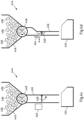
- FIGS. 4a-d show schematic views of embodiments of event generation devices which are particularly usable in an embodiment of a coupling method according to the present invention, as for example in the Figure 3
- a positioning system such as that described in the Figure 2 described location system may additionally comprise at least one event generating device.
- an event generation device 444 is shown which is configured to generate a defined movement path of a transponder 406.
- the event generation device 444 can comprise a transponder memory 446 containing a plurality of available transponders 406 and a singulation module 448 which can be actuated or triggered, for example, via a user interface (not shown), so that in particular a transponder experiences a defined course of events.
- the event generation device 444 also includes a guide 450 with optional guide elements 452, for example in the form of a downpipe.
- a guide 450 with optional guide elements 452, for example in the form of a downpipe.
- the event generation device 444 is actuated or activated, exactly one transponder 406 falls down the guide 450 due to gravity and experiences a defined movement and in particular acceleration depending on the design of the guide 450 and possibly the guide elements 452. It is understood that the design of the guide 450 and possibly the guide elements 452 can be arbitrary, as long as a defined and always essentially the same movement and in particular acceleration is generated.
- a holder 454 is arranged under the guide 450 to hold the transponder 406.
- a reference movement range can be determined by a calibration run in which a large number of transponders pass through the guide 450 and the recorded movement patterns are evaluated.
- an event generation device 444 is shown which is set up to generate a defined temperature profile of a transponder 406.
- a temperature control device 458 e.g. heating and/or cooling
- a transponder 406 temporaryly lying on the flap 460 for a predefined period of time.
- the flap 460 can be opened automatically so that the transponder 406 enters the receptacle 454.
- the ambient temperature can also be included in the evaluation.
- an event generation device 444 is shown which is set up to generate a defined brightness curve of a transponder 406.
- a lighting device 462 e.g. lamp and/or shading system
- the flap 460 can be opened automatically so that the transponder 406 enters the receptacle 454.
- the ambient brightness can also be included in the evaluation.
- a reference brightness range can be determined by a calibration run in which a large number of transponders are illuminated or shaded and the recorded brightness curves or patterns are evaluated.
- a reference scanning range can be determined by a calibration run in which a large number of transponders are exposed to a specific scanning pattern and the recorded scanning patterns are evaluated.
- event generation devices 444 of the Figures 4a to d can be combined with each other and/or a location system can comprise two or more event generating devices 444.
- the Figure 5 shows a diagram of another embodiment of a coupling method according to the present invention, which can be used for example in the positioning system according to Figure 2 can be used.
- step 501 providing a (for example according to the method according to Figure 3 ) generated coupling data set.
- step 503 (in particular analogous to step 303) a second coupling data set generated by the at least one receiving device received transponder data set of a second transponder.
- the Figure 6 shows a diagram of another embodiment of a coupling method according to the present invention, which can be used for example in the positioning system according to Figure 2 can be used.
- an object identifier of a digital object is provided, as previously described.
- a first transponder data set of a first transponder received by at least one receiving device of a positioning system is obtained, as previously described.
- step 605 a second transponder data set of a second transponder received by the at least one receiving device can be obtained, as already described.
- step 607 a determination is made whether the first event history contained in the received transponder data set satisfies a predefined event criterion, as previously described.
- step 609 a determination may be made whether the second event history contained in the received transponder data set satisfies a predefined event criterion, as previously described.
- step 611 it may be determined whether the second event sequence and the first event sequence satisfy a synchronicity criterion.
- the synchronicity criterion may define a time constraint.
- the synchronicity criterion may specify that the first event sequence and the second event sequence must occur substantially simultaneously.
- the first transponder and the second transponder must experience the event, such as a movement (for example, shaking the two transponders at the same time), a change in temperature, a touch pattern (for example, pressing the respective button at the same time), a change in brightness and/or the like, at the same time.
- a movement for example, shaking the two transponders at the same time
- a change in temperature for example, a touch pattern (for example, pressing the respective button at the same time)
- a change in brightness and/or the like at the same time.
- step 611 may be performed first and then steps 607 and 609.
- coupling of the digital object to the first transponder and the second transponder may be performed by generating the coupling data set containing the object identifier of the digital object, the first transponder identifier of the first transponder, and the second transponder identifier of the second transponder, only if it is determined at least that the first event sequence satisfies the predefined event criterion, the second event sequence satisfies the predefined event criterion, and the first event sequence and the second event sequence satisfy the synchronicity criterion.
- step 701 an object identifier of a first digital object is provided and in step 703, a further object identifier of a further digital object is provided.
- step 705 (in particular analogous to step 303), a first transponder data set of a first transponder received by the at least one receiving device can be obtained.
- step 707 a determination can be made as to whether the first event history contained in the received first transponder data set satisfies a predefined event criterion.
- coupling of the digital object and the further digital object to the first transponder may be performed by generating a coupling data set containing the object identifier of the digital object, the further object identifier of the further object and the first transponder identifier of the first transponder, only if it is at least determined that the first event sequence satisfies the predefined event criterion.
- a plurality of transponders can be linked to a plurality of digital objects by a combination of methods 5 and/or 6 and 7.
- order papers are printed and prioritized in their order in a work queue for each production area.
- the printed order papers are taken from the sorted stack and moved through production with the starting materials.
- the prioritization can be changed using the current technology. It is also possible to not remove the top order using the current technology.
- the production orders can be written to a memory instead of physical paper printing (or in addition to it) ("e-printing"). This can be done centrally for all production areas, but also decentrally for each area individually.
- e-printing In addition to the object identifiers, other parameters can be stored (e.g. subdivision of production areas, prioritization, assignment to users or machines).
- the object identifiers in the memory form the work list in particular.
- the coupling of the production order or digital object with the transponder is carried out, for example, by removing a transponder from a transponder memory in the form of a container in an area that is illuminated by at least one receiving device of the tracking system.
- the removal can be detected by the at least one receiving device and generate an RTLS trigger that is linked to the transponder identification.
- This can be, for example, a specific movement profile and/or a defined change of location and/or other sensor signals from the transponder, as described.
- a production order with the associated object identifier is selected from the order memory at random or based on defined criteria and linked to the transponder identifier, as described.
- the transponders with the products to be processed can now physically move through production. These changes of location can then be evaluated within the RTLS system and used, for example, to automate production control.
- the production orders in the memory can be provided with parameters (e.g. division into production areas, prioritization, assignment to employees or machines). These can either come from the location system, in particular an ERP system of the location system, and/or be added manually via an interface. This means that, for example, depending on the location of the event that triggers the coupling, an order can be selected for the assigned production area, as described.
- the order in the memory can be changed in its sequence up to the time of coupling (manually and/or by changing parameters or by changing the sequence rules).
Landscapes
- Business, Economics & Management (AREA)
- Engineering & Computer Science (AREA)
- Economics (AREA)
- Computer Networks & Wireless Communication (AREA)
- Signal Processing (AREA)
- Marketing (AREA)
- Quality & Reliability (AREA)
- Finance (AREA)
- Entrepreneurship & Innovation (AREA)
- Human Resources & Organizations (AREA)
- Accounting & Taxation (AREA)
- Operations Research (AREA)
- Development Economics (AREA)
- Strategic Management (AREA)
- Tourism & Hospitality (AREA)
- Physics & Mathematics (AREA)
- General Business, Economics & Management (AREA)
- General Physics & Mathematics (AREA)
- Theoretical Computer Science (AREA)
- Radar Systems Or Details Thereof (AREA)
Applications Claiming Priority (1)
| Application Number | Priority Date | Filing Date | Title |
|---|---|---|---|
| DE102023116121.0A DE102023116121A1 (de) | 2023-06-20 | 2023-06-20 | Kopplungsverfahren |
Publications (1)
| Publication Number | Publication Date |
|---|---|
| EP4481652A1 true EP4481652A1 (fr) | 2024-12-25 |
Family
ID=91376967
Family Applications (1)
| Application Number | Title | Priority Date | Filing Date |
|---|---|---|---|
| EP24179762.0A Pending EP4481652A1 (fr) | 2023-06-20 | 2024-06-04 | Procédé de couplage |
Country Status (2)
| Country | Link |
|---|---|
| EP (1) | EP4481652A1 (fr) |
| DE (1) | DE102023116121A1 (fr) |
Citations (3)
| Publication number | Priority date | Publication date | Assignee | Title |
|---|---|---|---|---|
| US20030227382A1 (en) * | 2002-06-11 | 2003-12-11 | Breed David S. | Low power remote asset monitoring |
| US20080100706A1 (en) * | 2002-06-11 | 2008-05-01 | Intelligent Technologies International, Inc. | Asset Monitoring System Using Multiple Imagers |
| WO2016160799A1 (fr) * | 2015-03-30 | 2016-10-06 | Precyse, Inc. | Procédé de commande de surveillance et de rapport de localisation |
Family Cites Families (4)
| Publication number | Priority date | Publication date | Assignee | Title |
|---|---|---|---|---|
| US7646336B2 (en) * | 2006-03-24 | 2010-01-12 | Containertrac, Inc. | Automated asset positioning for location and inventory tracking using multiple positioning techniques |
| US9462357B2 (en) * | 2013-09-11 | 2016-10-04 | Michael Westick | Automated asset tracking system and method |
| WO2021150848A1 (fr) * | 2020-01-24 | 2021-07-29 | Wiser Systems, Inc. | Détermination de l'emplacement d'étiquettes dans un environnement |
| IT202100005318A1 (it) * | 2021-03-08 | 2022-09-08 | Stetel S R L | Sistema di tracciatura della posizione di oggetti in un ambiente di lavoro |
-
2023
- 2023-06-20 DE DE102023116121.0A patent/DE102023116121A1/de active Pending
-
2024
- 2024-06-04 EP EP24179762.0A patent/EP4481652A1/fr active Pending
Patent Citations (3)
| Publication number | Priority date | Publication date | Assignee | Title |
|---|---|---|---|---|
| US20030227382A1 (en) * | 2002-06-11 | 2003-12-11 | Breed David S. | Low power remote asset monitoring |
| US20080100706A1 (en) * | 2002-06-11 | 2008-05-01 | Intelligent Technologies International, Inc. | Asset Monitoring System Using Multiple Imagers |
| WO2016160799A1 (fr) * | 2015-03-30 | 2016-10-06 | Precyse, Inc. | Procédé de commande de surveillance et de rapport de localisation |
Non-Patent Citations (1)
| Title |
|---|
| LU YAN ET AL: "The Internet of Things: From RFID to the Next-Generation Pervasive Networked Systems", 5 March 2008, AUERBACH PUBLICATIONS, ISBN: 978-1-42-005281-7, XP055120439 * |
Also Published As
| Publication number | Publication date |
|---|---|
| DE102023116121A1 (de) | 2024-12-24 |
Similar Documents
| Publication | Publication Date | Title |
|---|---|---|
| EP3529675B1 (fr) | Commande de fabrication, basée sur la localisation de personnes dans un espace intérieur, dans l'industrie de transformation des métaux | |
| DE102017120382B3 (de) | Bild-gestütztes zuordnen eines bearbeitungsplans zu einem mobileinheitsdatensatz einer mobileinheit eines innenraum-ortungssystems | |
| EP2888060B1 (fr) | Procédé et dispositif de transport des objets rectangulaires | |
| DE19824528C1 (de) | Verfahren zum Detektieren eines oder mehrerer Transponder sowie Anordnung und Verwendung einer solchen Anordnung | |
| DE102017121098A1 (de) | Objektverfolgung-basierte steuerung von fertigungsprozessen in der metallverarbeitenden industrie | |
| EP3679435A1 (fr) | Affectation assistée d'une pièce à une unité mobile d'un système de localisation en intérieur | |
| DE102017215613A1 (de) | Produktionsanlage und Produktionssteuerungsverfahren zur Steuerung einer Produktionsanlage | |
| EP3291144B1 (fr) | Dispositif rfid et procede de reconnaissance d'occupation de casier | |
| WO2018073421A2 (fr) | Commande, basée sur la localisation dans un espace intérieur, de processus de fabrication dans l'industrie de transformation des métaux | |
| DE102017120378A1 (de) | Innenraum-ortung-basierte steuerung von fertigungsprozessen in der metallverarbeitenden industrie | |
| DE102017120383A1 (de) | Innenraum-personenortung-basierte fertigungssteuerung in der metallverarbeitenden industrie | |
| CH706471A1 (de) | Mobile Einheit zur Bereitstellung von produktionsanlagespezifischen Funktionen. | |
| EP3388987A1 (fr) | Aide au stockage et à la recherche d'objets dans une installation de stockage | |
| WO2016150890A1 (fr) | Système et procédé de poursuite du porteur d'une unité de communication mobile | |
| EP1886527B1 (fr) | Systeme et procede de localisation et emetteur de donnees de position mobile | |
| EP4481652A1 (fr) | Procédé de couplage | |
| DE102018114012B4 (de) | Rfid-system und informationsverarbeitungsverfahren | |
| WO2023006171A1 (fr) | Procédé de détermination d'une mesure d'un produit dans un dispositif de présentation de produit | |
| DE102012016552A1 (de) | Kommissioniersystem | |
| EP4550624A2 (fr) | Procédé de localisation d'une étiquette de rayon électronique | |
| DE102022104945A1 (de) | Verfahren zur Nachverfolgung eines Gerätes, Gerät sowie Arbeitssystem | |
| DE102018215845A1 (de) | Sensor-basierte Überwachung von Waren | |
| DE202021004393U1 (de) | System zur Ortsbestimmung von Regalschienen-Equipment | |
| DE102005036088A1 (de) | Verfahren und Vorrichtung zum Orten eines Objekts | |
| DE102023116891A1 (de) | Verfahren zur Steuerung eines Durchlaufes an herzustellenden Gütern durch eine industrielle Produktionsumgebung |
Legal Events
| Date | Code | Title | Description |
|---|---|---|---|
| PUAI | Public reference made under article 153(3) epc to a published international application that has entered the european phase |
Free format text: ORIGINAL CODE: 0009012 |
|
| STAA | Information on the status of an ep patent application or granted ep patent |
Free format text: STATUS: THE APPLICATION HAS BEEN PUBLISHED |
|
| AK | Designated contracting states |
Kind code of ref document: A1 Designated state(s): AL AT BE BG CH CY CZ DE DK EE ES FI FR GB GR HR HU IE IS IT LI LT LU LV MC ME MK MT NL NO PL PT RO RS SE SI SK SM TR |
|
| P01 | Opt-out of the competence of the unified patent court (upc) registered |
Free format text: CASE NUMBER: APP_12/2025 Effective date: 20250102 |
|
| STAA | Information on the status of an ep patent application or granted ep patent |
Free format text: STATUS: REQUEST FOR EXAMINATION WAS MADE |
|
| 17P | Request for examination filed |
Effective date: 20250527 |