EP4550624A2 - Procédé de localisation d'une étiquette de rayon électronique - Google Patents
Procédé de localisation d'une étiquette de rayon électronique Download PDFInfo
- Publication number
- EP4550624A2 EP4550624A2 EP25162712.1A EP25162712A EP4550624A2 EP 4550624 A2 EP4550624 A2 EP 4550624A2 EP 25162712 A EP25162712 A EP 25162712A EP 4550624 A2 EP4550624 A2 EP 4550624A2
- Authority
- EP
- European Patent Office
- Prior art keywords
- shelf
- access point
- radio
- shelf label
- supply device
- Prior art date
- Legal status (The legal status is an assumption and is not a legal conclusion. Google has not performed a legal analysis and makes no representation as to the accuracy of the status listed.)
- Pending
Links
Images



Classifications
-
- G—PHYSICS
- G06—COMPUTING OR CALCULATING; COUNTING
- G06K—GRAPHICAL DATA READING; PRESENTATION OF DATA; RECORD CARRIERS; HANDLING RECORD CARRIERS
- G06K7/00—Methods or arrangements for sensing record carriers, e.g. for reading patterns
- G06K7/10—Methods or arrangements for sensing record carriers, e.g. for reading patterns by electromagnetic radiation, e.g. optical sensing; by corpuscular radiation
- G06K7/10009—Methods or arrangements for sensing record carriers, e.g. for reading patterns by electromagnetic radiation, e.g. optical sensing; by corpuscular radiation sensing by radiation using wavelengths larger than 0.1 mm, e.g. radio-waves or microwaves
- G06K7/10297—Methods or arrangements for sensing record carriers, e.g. for reading patterns by electromagnetic radiation, e.g. optical sensing; by corpuscular radiation sensing by radiation using wavelengths larger than 0.1 mm, e.g. radio-waves or microwaves arrangements for handling protocols designed for non-contact record carriers such as RFIDs NFCs, e.g. ISO/IEC 14443 and 18092
- G06K7/10306—Methods or arrangements for sensing record carriers, e.g. for reading patterns by electromagnetic radiation, e.g. optical sensing; by corpuscular radiation sensing by radiation using wavelengths larger than 0.1 mm, e.g. radio-waves or microwaves arrangements for handling protocols designed for non-contact record carriers such as RFIDs NFCs, e.g. ISO/IEC 14443 and 18092 ultra wide band
-
- H—ELECTRICITY
- H02—GENERATION; CONVERSION OR DISTRIBUTION OF ELECTRIC POWER
- H02J—ELECTRIC POWER NETWORKS; CIRCUIT ARRANGEMENTS OR SYSTEMS FOR SUPPLYING OR DISTRIBUTING ELECTRIC POWER; SYSTEMS FOR STORING ELECTRIC ENERGY
- H02J50/00—Circuit arrangements or systems for wireless supply or distribution of electric power
- H02J50/20—Circuit arrangements or systems for wireless supply or distribution of electric power using microwaves or radio frequency waves
-
- G—PHYSICS
- G01—MEASURING; TESTING
- G01S—RADIO DIRECTION-FINDING; RADIO NAVIGATION; DETERMINING DISTANCE OR VELOCITY BY USE OF RADIO WAVES; LOCATING OR PRESENCE-DETECTING BY USE OF THE REFLECTION OR RERADIATION OF RADIO WAVES; ANALOGOUS ARRANGEMENTS USING OTHER WAVES
- G01S1/00—Beacons or beacon systems transmitting signals having a characteristic or characteristics capable of being detected by non-directional receivers and defining directions, positions, or position lines fixed relatively to the beacon transmitters; Receivers co-operating therewith
- G01S1/02—Beacons or beacon systems transmitting signals having a characteristic or characteristics capable of being detected by non-directional receivers and defining directions, positions, or position lines fixed relatively to the beacon transmitters; Receivers co-operating therewith using radio waves
- G01S1/04—Details
- G01S1/042—Transmitters
- G01S1/0423—Mounting or deployment thereof
-
- G—PHYSICS
- G01—MEASURING; TESTING
- G01S—RADIO DIRECTION-FINDING; RADIO NAVIGATION; DETERMINING DISTANCE OR VELOCITY BY USE OF RADIO WAVES; LOCATING OR PRESENCE-DETECTING BY USE OF THE REFLECTION OR RERADIATION OF RADIO WAVES; ANALOGOUS ARRANGEMENTS USING OTHER WAVES
- G01S5/00—Position-fixing by co-ordinating two or more direction or position line determinations; Position-fixing by co-ordinating two or more distance determinations
- G01S5/02—Position-fixing by co-ordinating two or more direction or position line determinations; Position-fixing by co-ordinating two or more distance determinations using radio waves
- G01S5/0205—Details
-
- G—PHYSICS
- G06—COMPUTING OR CALCULATING; COUNTING
- G06Q—INFORMATION AND COMMUNICATION TECHNOLOGY [ICT] SPECIALLY ADAPTED FOR ADMINISTRATIVE, COMMERCIAL, FINANCIAL, MANAGERIAL OR SUPERVISORY PURPOSES; SYSTEMS OR METHODS SPECIALLY ADAPTED FOR ADMINISTRATIVE, COMMERCIAL, FINANCIAL, MANAGERIAL OR SUPERVISORY PURPOSES, NOT OTHERWISE PROVIDED FOR
- G06Q30/00—Commerce
- G06Q30/06—Buying, selling or leasing transactions
-
- H—ELECTRICITY
- H02—GENERATION; CONVERSION OR DISTRIBUTION OF ELECTRIC POWER
- H02J—ELECTRIC POWER NETWORKS; CIRCUIT ARRANGEMENTS OR SYSTEMS FOR SUPPLYING OR DISTRIBUTING ELECTRIC POWER; SYSTEMS FOR STORING ELECTRIC ENERGY
- H02J50/00—Circuit arrangements or systems for wireless supply or distribution of electric power
- H02J50/10—Circuit arrangements or systems for wireless supply or distribution of electric power using inductive coupling
-
- H—ELECTRICITY
- H02—GENERATION; CONVERSION OR DISTRIBUTION OF ELECTRIC POWER
- H02J—ELECTRIC POWER NETWORKS; CIRCUIT ARRANGEMENTS OR SYSTEMS FOR SUPPLYING OR DISTRIBUTING ELECTRIC POWER; SYSTEMS FOR STORING ELECTRIC ENERGY
- H02J50/00—Circuit arrangements or systems for wireless supply or distribution of electric power
- H02J50/40—Circuit arrangements or systems for wireless supply or distribution of electric power using two or more transmitting or receiving devices
-
- H—ELECTRICITY
- H02—GENERATION; CONVERSION OR DISTRIBUTION OF ELECTRIC POWER
- H02J—ELECTRIC POWER NETWORKS; CIRCUIT ARRANGEMENTS OR SYSTEMS FOR SUPPLYING OR DISTRIBUTING ELECTRIC POWER; SYSTEMS FOR STORING ELECTRIC ENERGY
- H02J7/00—Circuit arrangements for charging or discharging batteries or for supplying loads from batteries
- H02J7/34—Parallel operation in networks using both storage and other DC sources, e.g. providing buffering
- H02J7/342—The other DC source being a battery actively interacting with the first one, i.e. battery to battery charging
-
- H—ELECTRICITY
- H04—ELECTRIC COMMUNICATION TECHNIQUE
- H04W—WIRELESS COMMUNICATION NETWORKS
- H04W4/00—Services specially adapted for wireless communication networks; Facilities therefor
- H04W4/02—Services making use of location information
-
- H—ELECTRICITY
- H04—ELECTRIC COMMUNICATION TECHNIQUE
- H04W—WIRELESS COMMUNICATION NETWORKS
- H04W4/00—Services specially adapted for wireless communication networks; Facilities therefor
- H04W4/02—Services making use of location information
- H04W4/021—Services related to particular areas, e.g. point of interest [POI] services, venue services or geofences
-
- H—ELECTRICITY
- H04—ELECTRIC COMMUNICATION TECHNIQUE
- H04W—WIRELESS COMMUNICATION NETWORKS
- H04W4/00—Services specially adapted for wireless communication networks; Facilities therefor
- H04W4/02—Services making use of location information
- H04W4/023—Services making use of location information using mutual or relative location information between multiple location based services [LBS] targets or of distance thresholds
-
- H—ELECTRICITY
- H04—ELECTRIC COMMUNICATION TECHNIQUE
- H04W—WIRELESS COMMUNICATION NETWORKS
- H04W4/00—Services specially adapted for wireless communication networks; Facilities therefor
- H04W4/02—Services making use of location information
- H04W4/029—Location-based management or tracking services
-
- G—PHYSICS
- G01—MEASURING; TESTING
- G01S—RADIO DIRECTION-FINDING; RADIO NAVIGATION; DETERMINING DISTANCE OR VELOCITY BY USE OF RADIO WAVES; LOCATING OR PRESENCE-DETECTING BY USE OF THE REFLECTION OR RERADIATION OF RADIO WAVES; ANALOGOUS ARRANGEMENTS USING OTHER WAVES
- G01S2201/00—Indexing scheme relating to beacons or beacon systems transmitting signals capable of being detected by non-directional receivers and defining directions, positions, or position lines fixed relatively to the beacon transmitters
- G01S2201/01—Indexing scheme relating to beacons or beacon systems transmitting signals capable of being detected by non-directional receivers and defining directions, positions, or position lines fixed relatively to the beacon transmitters adapted for specific applications or environments
-
- G—PHYSICS
- G01—MEASURING; TESTING
- G01S—RADIO DIRECTION-FINDING; RADIO NAVIGATION; DETERMINING DISTANCE OR VELOCITY BY USE OF RADIO WAVES; LOCATING OR PRESENCE-DETECTING BY USE OF THE REFLECTION OR RERADIATION OF RADIO WAVES; ANALOGOUS ARRANGEMENTS USING OTHER WAVES
- G01S2205/00—Position-fixing by co-ordinating two or more direction or position line determinations; Position-fixing by co-ordinating two or more distance determinations
- G01S2205/01—Position-fixing by co-ordinating two or more direction or position line determinations; Position-fixing by co-ordinating two or more distance determinations specially adapted for specific applications
-
- H—ELECTRICITY
- H02—GENERATION; CONVERSION OR DISTRIBUTION OF ELECTRIC POWER
- H02J—ELECTRIC POWER NETWORKS; CIRCUIT ARRANGEMENTS OR SYSTEMS FOR SUPPLYING OR DISTRIBUTING ELECTRIC POWER; SYSTEMS FOR STORING ELECTRIC ENERGY
- H02J50/00—Circuit arrangements or systems for wireless supply or distribution of electric power
- H02J50/40—Circuit arrangements or systems for wireless supply or distribution of electric power using two or more transmitting or receiving devices
- H02J50/402—Circuit arrangements or systems for wireless supply or distribution of electric power using two or more transmitting or receiving devices the two or more transmitting or the two or more receiving devices being integrated in the same unit, e.g. power mats with several coils or antennas with several sub-antennas
-
- H—ELECTRICITY
- H02—GENERATION; CONVERSION OR DISTRIBUTION OF ELECTRIC POWER
- H02J—ELECTRIC POWER NETWORKS; CIRCUIT ARRANGEMENTS OR SYSTEMS FOR SUPPLYING OR DISTRIBUTING ELECTRIC POWER; SYSTEMS FOR STORING ELECTRIC ENERGY
- H02J50/00—Circuit arrangements or systems for wireless supply or distribution of electric power
- H02J50/80—Circuit arrangements or systems for wireless supply or distribution of electric power involving the exchange of data, concerning supply or distribution of electric power, between transmitting devices and receiving devices
-
- H—ELECTRICITY
- H02—GENERATION; CONVERSION OR DISTRIBUTION OF ELECTRIC POWER
- H02J—ELECTRIC POWER NETWORKS; CIRCUIT ARRANGEMENTS OR SYSTEMS FOR SUPPLYING OR DISTRIBUTING ELECTRIC POWER; SYSTEMS FOR STORING ELECTRIC ENERGY
- H02J50/00—Circuit arrangements or systems for wireless supply or distribution of electric power
- H02J50/90—Circuit arrangements or systems for wireless supply or distribution of electric power involving detection or optimisation of position, e.g. alignment
-
- H—ELECTRICITY
- H04—ELECTRIC COMMUNICATION TECHNIQUE
- H04W—WIRELESS COMMUNICATION NETWORKS
- H04W4/00—Services specially adapted for wireless communication networks; Facilities therefor
- H04W4/30—Services specially adapted for particular environments, situations or purposes
- H04W4/33—Services specially adapted for particular environments, situations or purposes for indoor environments, e.g. buildings
-
- H—ELECTRICITY
- H04—ELECTRIC COMMUNICATION TECHNIQUE
- H04W—WIRELESS COMMUNICATION NETWORKS
- H04W4/00—Services specially adapted for wireless communication networks; Facilities therefor
- H04W4/30—Services specially adapted for particular environments, situations or purposes
- H04W4/38—Services specially adapted for particular environments, situations or purposes for collecting sensor information
-
- H—ELECTRICITY
- H04—ELECTRIC COMMUNICATION TECHNIQUE
- H04W—WIRELESS COMMUNICATION NETWORKS
- H04W4/00—Services specially adapted for wireless communication networks; Facilities therefor
- H04W4/80—Services using short range communication, e.g. near-field communication [NFC], radio-frequency identification [RFID] or low energy communication
Definitions
- the invention relates to a method for locating an electronic shelf label.
- the invention has for its object to provide an improved method for locating an electronic shelf label in an ESL system, in which the above-mentioned problems are overcome.
- the subject matter of the invention is thus a method for locating an unknown electronic shelf label, in particular implemented as an electronic shelf label display, of an electronic shelf label system, wherein the system comprises a number of known access points which are positioned at different positions, each at a distance from a shelf, wherein the shelf has at least one shelf rail and wherein one of the shelf rails has at least one electronic shelf label which is designed to be supplied with energy in a contactless manner, and an electronic supply device located on the shelf rail which is designed to supply energy to the at least one shelf label in a contactless manner, wherein the method comprises the following method steps, namely determining the position of the electronic supply device with respect to the known access points by using ultra-wideband radio communication between the access points and the supply device.
- the measures according to the invention have the advantage that, in contrast to known measures, the location determination for one or more shelf labels is no longer dependent on the absolute position of other shelf labels being known, which in these known measures serve as static anchor points for position determination. Instead, dynamic anchor points implemented by the supply devices are now used. These can change their position in the room over time, for example, due to a rearrangement of the shelf or a rearrangement of the shelves to which the shelf rails are attached. Therefore, before a location determination for a shelf label is carried out, a A location determination for the supply device is carried out and, based on this, i.e., based on this position of the supply device, the position of a shelf label is determined or narrowed down.
- the fact that the shelf label whose position is to be determined or narrowed down is located on the shelf rail on which the respective supply device is also provided or located is taken into account.
- the position of the shelf label supplied with the help of the respective supply device is de facto determined automatically, because it can only be positioned on the respective shelf rail. Since several shelf rails are usually installed next to each other and/or one above the other on a shelf and the dimensions (lengths) of the shelf rails (e.g. a server of the store) as well as the location at which the supply device is mounted on the shelf rail are known, the orientation of the shelf and thus also the orientation of the shelf rails can be determined automatically (e.g. with the help of the mentioned server) by determining the position of the plurality of supply devices installed on the shelf and thus actually limit the position of the respective shelf label to a spatial area in which the respective shelf rail is located.
- Ultra-wideband radio communication is radio communication based on ultra -wideband (UWB) technology. Its key feature is the use of extremely large frequency ranges with a bandwidth of at least 500 MHz or at least 20% of the arithmetic mean of the lower and upper limit frequencies of the used frequency range.
- Such an electronic shelf label can provide a wide variety of functionalities or fulfill a variety of functions.
- the shelf label can, for example, be configured or designed to record environmental parameters, such as temperature or humidity, or as an input element for receiving user input interaction (e.g., capturing a fingerprint or keystroke), or as a display medium for presenting information to the user, namely as a shelf label display.
- the shelf label is designed such that it can be attached to the shelf rail in question and is supplied with energy there in the manner described in detail below.
- This method is based on determining the position of the electronic supply device by determining the distance between it and each of the involved access points using the respective ultra-wideband radio communication. This involves a "flight-of-time” measurement and, if necessary, an "angle-of-arrival” determination. This allows for a very precise determination of the location of the respective supply device through subsequent measures such as triangulation, etc.
- the at least one electronic shelf label installed on the shelf is identified during its power supply.
- the power supply starts the shelf label's electronics, so that the shelf label is ready for use with its functionality. Then, while the shelf label is powered, it is identified by querying its unique identifier. This query is also performed by the power supply device. The identifier thus determined is made available for retrieval at the power supply device or at another Communication (wired or wireless) for further processing.
- the contactless energy transfer is achieved by using at least one first conductor loop formed on the shelf rail for this purpose, which is connected to the supply device via its two loop connections and serves for inductive coupling with a spatially corresponding (located nearby) second conductor loop of the shelf label. If the conductor loop extends along the entire length of the shelf rail, all shelf labels positioned along the shelf rail can be identified, thus establishing that all of these identified shelf labels are positioned near the position of the supply device and, in any case, along the shelf rail.
- the shelf labels can be programmed to transmit their identifiers at randomly selected times within a time window (single or multiple times) to ensure individual reception by the supply device.
- An anti-collision method known from RFID technology, for example, can also be used for this contactless transmission to ensure individual reception by the supply device.
- first conductor loops positioned at different locations along the shelf rail. These loops allow for spatial resolution along the shelf rail, i.e., along its longitudinal extension. The accuracy of the location determination depends on the number and length of the zones covered by the individual first conductor loops.
- a locally limited, i.e. individual, energy supply is carried out at the location of the respective first conductor loop if a shelf label is positioned there. Since the supply device is informed about how many first conductor loops are attached to its shelf rail and in which order and/or at which distances (measured from its own position or measured relative to one conductor loop to the next) these occur along the shelf rail, Each shelf label, which can be activated or identified by an energy supply, determines its position along the shelf rail.
- the contactless energy supply implemented with the aid of the supply device can be based on a proprietary technical solution or on a standardized technology such as RFID technology.
- an NFC interface is particularly preferably used on both the shelf label side and the supply device side for contactless energy supply, in particular also for identification.
- the first conductor loop formed on the shelf rail forms a component of the NFC interface of the supply device.
- the supply device is preferably configured for individual use of the respective first conductor loop, for example, to use the first conductor loops sequentially one after the other.
- the supply device is preferably configured for selective (or sequential) switching (multiplexing) between the first conductor loops in order to always use only one individual first conductor loop. Such switching can be implemented, for example, with the help of an "analog switch" known in the field of electronics.
- RFID stands for "Radio Frequency Identification.”
- the technology is specified, for example, in the ISO/IEC 18000 standard.
- NFC Near Field Communication
- the position of an electronic shelf label can be determined, but also the image content to be displayed using this shelf label (implemented as a shelf label display) can be defined, i.e., transmitted to the electronics of the shelf label. This preferably occurs during the period in which the shelf label is supplied with energy, i.e., its electronics are active, with corresponding command and/or image content data being transmitted to the shelf label.
- the shelf label display has an energy-saving display unit, in particular based on electronic ink or electronic paper technology, etc.
- Such a reflective screen can also be realized using other technologies, known, for example, under the terms “electrowetting” or "MEMS.”
- the screen can, for example, be designed for black-and-white, grayscale, black-white-red, or even black-white-yellow display. Future developments that enable full-color or multi-color display are also intended to be included.
- Such a screen is generally a reflective, i.e. passive, non-self-illuminating screen in which the - relatively static - information reproduction is based on the fact that light generated by an external (artificial or natural) light source shines onto the screen and is reflected from there to the viewer.
- the shelf label or its display unit is supplied with both power and data via the NFC interface. This means that while the power is being supplied via the NFC interface, data can also be transmitted via this NFC interface, which is then processed by the display unit to change the image content on its screen. Once the image content has been changed, the display unit can also transmit corresponding status information via the NFC interface, indicating that the image content has been successfully changed. Once the image content has been changed, and if necessary also after the status information has been transmitted, the power supply via the NFC interface can be terminated, after which the image content on the screen remains unchanged until the next desired change.
- shelf label primarily allows the shelf label to be implemented without its own power supply, such as a battery or accumulator, both of which are relatively expensive. Furthermore, a conventional shelf label must be designed in such a way that the energy storage devices are replaceable for maintenance or replacement of the battery or accumulator. If necessary, the shelf label in question only uses a capacitor for short-term, temporary smoothing or stabilization of the internal supply voltage. The shelf label is therefore designed in such a way that its electronics for communication or updating the screen content, in particular its electronic control system, are only active when supplied with power from the external electronic supply device. The housing can be completely and permanently encapsulated because replacing the energy storage device is no longer necessary, meaning it can only be opened for recycling purposes (e.g., with special tools).
- This extremely reduced shelf label only has basic functionality, such as standardized NFC communication with a standardized power supply during NFC communication. These tasks can be implemented using a simple NFC controller. Updates to the screen of the energy-saving display unit and the associated status report are not handled directly by the shelf label via wireless communication with an access point, as is the case with conventional systems, but rather by the intermediate power supply device, which in turn can communicate with the access point via a suitable (and essentially freely selectable) wireless communication method.
- a time slot communication method can be used, in particular a proprietary time slot communication method as described in WO2015/124197 , pages 2 to 4, the specific disclosure of which is hereby incorporated by reference.
- a communication protocol based on the standards or specifications ZigBee, Bluetooth, or WiFi, etc. can also be used for wireless communication.
- both the access point and the supply device can be provided with at least one additional radio module that provides one of the aforementioned radio technologies, in addition to a radio module that provides UWB radio capability.
- Each of the separate radio modules can have its own antenna configuration, consisting of a single antenna or a number of individual antennas, and contain associated electronics. This enables the use of UWB radio communication exclusively for location determination, while simultaneously allowing communication via the additional radio module to control the shelf label via the supply device.
- position-relevant results of the ultra-wideband radio communication are transmitted either by cable or radio from the supply facility or from the involved access point to a data processing device for determining the location of the supply facility(ies).
- These position-relevant results can be the determined distances between the communication partners (supply facility and access point) or the signal propagation times during communication between the communication partners, from which the position of the respective supply facility in relation to the access points is then determined. From this, based on the knowledge of the exact position of the involved access points, the absolute position of the respective supply facility can then be determined, which is more accurate the more access points are involved.
- the identity of a shelf label identified by the supply device during its power supply is communicated to said data processing device, and the location of the respective shelf label relative to the previously determined location of the respective supply device is at least narrowed down at the data processing device.
- the dimensions (longitudinal extent) of the respective shelf rails can be taken into account, which ultimately defines the permissible limits for the distance between an identified shelf label and the supply device supplying this shelf label on the respective shelf rail.
- the object's trajectory can be determined. This measure can be used to predict the time a user will arrive at a specific shelf or shelf rail, or to predict the length of time a user will stay in front of a shelf or shelf rail.
- information corresponding to the position of the item is displayed either on a screen of the item or on a shelf label positioned nearby, i.e., on its display unit.
- This functionality can be triggered, for example, when the item passes a threshold distance to the supply facility or is located for longer than a predefined period of time within a zone defined by the distance to a single shelf label display or the distances to a number of such supply facilities.
- the invention enables a two-stage localization of electronic shelf labels, whereby in a first step the position of one or more supply devices is determined, and in a second step the position of a shelf label is narrowed down within the framework of a power supply by the supply device.
- both process steps can also occur in reverse order. It is irrelevant whether the supply device always remains in the same place or not, because its relative position with respect to access points installed at fixed locations can be determined and updated repeatedly and, above all, relatively quickly using the ultra-broadband radio communication used.
- the multitude of supply devices in a store thus implement dynamically changeable anchor points with regard to their own position for locating the shelf labels assigned to them (which are supplied with energy by them).
- the supply device for the respective shelf rail implements a combined power and communication supply device for the shelf labels attached to the respective shelf rail.
- the supply device is thus configured or designed for local contactless power transmission as well as local contactless communication with the shelf labels attached to the shelf rail.
- Such a supply device can also be referred to as a shelf rail control device or shelf rail controller because it controls all activities of the shelf labels mounted on the respective shelf rail, which includes the display behavior or other functionalities mentioned above, the communication behavior, as well as the respective power supply.
- the electronics of the system's various devices can be implemented using a wide variety of passive and active electronic components, both discretely and in integrated form.
- a microprocessor with appropriate peripheral components or a microcontroller is preferably used, with software running to provide the various functionalities.
- So-called ASICs Application-Specific Integrated Circuits
- ASICs Application-Specific Integrated Circuits
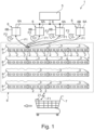
- FIG. 1 A part of a shelf label system 1 in a retail store is shown, comprising a number of identically designed, NFC-enabled, electronic shelf label displays 2, which are attached to four "smart" shelf rails 3 positioned next to one another (in a row along the width of a shelf 9), with the shelf rails 3 being seen essentially in a frontal view.
- Each shelf rail 3 has an electronic supply device 4 for the contactless power supply of the shelf label displays 2 and for contactless communication with a powered shelf label display 2, this being implemented using NFC technology.
- a data processing device implemented using a server 5, which is connected via cable to four identically designed access points 6, wherein the access points 6 are positioned at different locations in a retail store, and the server 5 knows these locations.
- the illustrated supply devices 4 are in radio contact with the leftmost access point 6, to which they are logically assigned, via first radio signals F1. This allows the image content of the shelf label displays 2 to be changed throughout the entire store from the server 5. if necessary, also query associated status information from the shelf label displays 2 and transmit it to the server 5.
- the shelf label display 2 of other shelves 9 not shown here can also be grouped and logically assigned to the other access points 6 shown, so that each access point 6 provides a subset of the totality of the shelf label displays 2 of the store with wireless transmission.
- Each access point 6 has two radio modules 6A and 6B, both of which are schematically indicated in the respective access point 6, separated from each other only by a dividing line.
- the first radio module 6A communicates via the first radio signal F1 and is used to define the image content. It uses ultra-wideband radio technology (known in technical jargon as UWB technology, where UWB stands for “ultra wide band”), and its electronics and antenna configuration (both not shown in detail) are designed to implement this technology.
- UWB technology known in technical jargon as UWB technology, where UWB stands for “ultra wide band”
- UWB ultra-wideband radio technology
- the second radio module 6B is designed as a supply transmitter and selectively supplies the supply devices 4 with energy by transmitting directed second radio signals F2.
- the second radio module 6B has, in addition to its electronics, a number of antennas with which the direction of energy transmission (ultimately the propagation of the second radio signal F2, which is transmitted at, for example, 5 watts) can be adjusted relatively precisely, so that the energy to be transmitted arrives precisely at a selected supply device 4.
- This energy transmission technology is known under the term "Power over WiFi,” and the electronics and antenna configuration of the second radio module 6B are designed accordingly.
- the "Power over WiFi” functionality i.e. the second radio module 6B, can be integrated into the access point 6 or implemented as a separate module/device that is, for example, linked to the first radio module 6A for control purposes.
- Each of the shelf rails 3 is mounted on an individual shelf 8 at its front edge.
- the four shelves 8 shown all belong to the only schematically indicated shelf 9. On the shelves 8 Various products can be presented, but these are not shown in this case.
- the Figure 1 a shopping cart 7 being moved to the left past the shelf 9.
- the shopping cart 7 has a mobile radio unit 21 configured for ultra-wideband radio communication.
- the radio unit 21 has, for example, battery-operated radio electronics and an associated antenna configuration (neither shown) and establishes a UWB radio connection to the supply devices 4 within its range using the first radio signals F1, on the basis of which the supply devices 4 can determine the distance to the radio unit 21.
- all shelf label displays 2 are, as mentioned, wirelessly assigned to the leftmost access point 6 and the changing of the image content is controlled with the aid of the first radio signals F1 via this leftmost access point 6.
- the location mode of system 1 several access points 6 are used, in this case all four.
- the distance between the respective supply device 4 and the respective access point 6 is determined using the first radio signals F1, which each of the access points 6 then exchanges with the supply device 4 in succession in a UWB radio communication.
- the distances thus determined are transmitted to the server 5 via a wired network (LAN), and the server 5 determines the spatial position of the respective supply device 4, knowing the absolute positions of the four access points 6.
- LAN wired network
- the block diagram according to the Figure 2 shows a first NFC interface 11 with its coupling coil 12, where NFC stands for "Near Field Communication.”
- NFC stands for "Near Field Communication.”
- the coupling coil 12 an inductive coupling can be established with another NFC-enabled device, in this case the supply device 4, specifically with the conductor loops L1 to L5 formed on the shelf rail 3 (see Fig. 3 ) when the coupling coil 12 is brought correspondingly close to one of the conductor loops L1 - L5, which is the case with the shelf label display 2 attached to the shelf rail 3.
- a first supply voltage VCC1 is generated with the aid of the first NFC interface 11 relative to a first reference potential GND1 for the operation of the entire shelf label display 2, which activates the electronics of the shelf label display 2 so that contactless bidirectional communication of data D can also be carried out via its first NFC interface 11.
- This electronics also includes an NFC controller, which provides the entire NFC functionality but is not shown in detail here, but is integrated into the first NFC interface 11.
- the block diagram also shows a display unit 13 connected to the first NFC interface 11, which is divided into a screen controller implemented as an electronic paper display controller 14 and a connected and thus controllable screen implemented as an electronic paper display screen 15.
- a screen controller implemented as an electronic paper display controller 14
- a connected and thus controllable screen implemented as an electronic paper display screen 15.
- the supply device 4 shown is designed for its own contactless supply of energy as well as for the contactless supply of energy to the shelf label displays 2.
- a supply receiver 23 suitable for receiving the second radio signal F2, which is equipped with an antenna configuration 24 (which can have several antennas) and electronics designed to receive and store the energy transmitted thereby in an internal electrical energy storage device 25 (rechargeable battery, accumulator) and generate the second supply voltage VCC2 relative to a second reference potential GND2.
- the supply device 4 can, for example, query or monitor the charge level of the energy storage device 25 using its control unit 20. As soon as the charge level drops below a certain level, the control unit 20 can request a (re)charge using the first radio signal F1. This request is received by the access point 6, to which the supply device 4 is logically (radio-technically) assigned. Since the exact geographical position (the three-dimensional coordinates) of each of the supply devices 4 and their unique identifier are known in system 1 (e.g., the server 5), because the position was previously determined, for example, using the location mode, the affected access point 6 can transmit the second radio signal F2 precisely directed towards the position of the respective supply device 4 requesting charging. There, the second radio signal F2 is received, and the energy transmitted with its help is used to charge the internal energy storage device 25 there.
- system 1 e.g., the server 5
- a printed circuit board 17 is also shown, the illustration of which in the Figure 1 has been omitted for reasons of clarity.
- the printed circuit board 17 carries five conductor loops L1 to L5, which in this case are designed with multiple loops or windings, each of which is indicated by the symbol of an electrical coil.
- the printed circuit board 17 is integrated into the relatively flat structure of the shelf rail 3.
- the supply device 4 can be soldered to this printed circuit board 17 or connected via cables or plugs, so that the conductor loops L1 to L5 are electrically contacted via their loop connections C1 to C5.
- the shelf label display 2 positioned there is also indicated.
- the electrical connection of the loop connections C1 to C5 with the supply device 4, but in particular with the electronics of its (second) NFC interface 18, is also shown.
- the second NFC interface 18 is, in the presence of an inductive coupling with the first NFC interface 11 of the shelf label display 2, for the contactless transmission of electrical energy to the shelf label display 2, as well as for bidirectional contactless communication of data with the shelf label display 2 activated by energy transfer.
- the conductor loops L1 to L5 are multiplexed using the specially designed NFC interface 18, meaning that only one of the conductor loops L1 to L5 is used at a time.
- An "analog switch" known in electronics can be used for this purpose.
- the supply device 4 further comprises an access point communication interface 19, which is used for radio-based communication with the Figure 1 It has an antenna configuration 19A, which can also be constructed from several individual antennas, and electronics with which the first radio signals F1 can be received or transmitted.
- the access point communication interface 19 is designed for ultra-wideband radio communication.
- the control unit 20 is used to control the internal processes as well as the power supply of the shelf label display 2 and the communication with the shelf label display 2, as well as the communication with the access point 6. It is implemented using a microcontroller that is connected to the second NFC interface 18 and the access point communication interface 19 as well as the supply receiver 23 via a bidirectional data bus.
- each of the shelf label displays 2 contains uniquely identifying identification data 16A to 16E, which are stored permanently and unalterably in an internal memory.
- the supply device 4 now sequentially activates the five shelf label displays 2. For this purpose, first, with the help of the rightmost conductor loop L1, an inductive coupling is established via the two NFC interfaces 11 and 18 with the (rightmost) shelf label display 2 positioned there, and energy is transferred to it so that the electronics of the shelf label display 2 are activated. Then, with the help of the coupled NFC interfaces 11 and 18, the unique first identification data 16A is retrieved and stored in the supply device 4. After that, the energy supply, i.e.
- the server 5 From this information, in particular from the relationship between the respective conductor loops L1 to L5 (e.g. the order in which they were used) and the identification data 16A to 16E obtained via the respective conductor loops L1 - L5, the server 5 now determines the respective shelf label display position 10A to 10E for each shelf label display 2 along the shelf rail 3, e.g. measured from a known reference position 16, e.g. the known position of the supply device 4, or from the right or left edge of the shelf rail 3.
- a known reference position 16 e.g. the known position of the supply device 4
- the server 5 can also determine the unambiguous position of each of the shelf label displays 2 in the room.
- the location mode is activated and the positions of the individual supply devices 4 are first determined using UWB radio communication as discussed. For those supply devices 4 for which only a minor or no change in location occurs, the process is terminated at this point because it is assumed that the associated shelf rails 3 have not undergone any change in location.
- the shelf label displays 2 installed there are identified in a second step during their individual energy supply and the identification data 16A to 16E to the server 5 to determine the respective position of each shelf label display 2. After that, the system 1 returns to normal mode.
- the supply devices 4 located at their new positions now simply register wirelessly with the nearest access point 6, because they are already known and previously registered in system 1, and are available there as usual. Re-registration can also occur with the nearest access point 6.
- the procedure can also be processed for these supply devices 4 as previously discussed, i.e., applied to all of the supply devices 4 and the shelf label displays 2 supplied with them, which ultimately leads to a complete inventory of the shelf label displays 2.
- This can be useful if the entirety of the positions is to be determined intentionally or if it is being tested whether individual shelf label displays 2 have been removed from the involved shelves or the shelf rails 3 there (although they were not accommodated), or have been accommodated to other locations, or have been moved along the shelf rails 3, etc.
- the access point communication interface 19 which is designed for ultra-wideband radio communication
- moving objects can also be tracked or identified using the first radio signals F1, which, like the one in the Figure 1
- the shopping cart 7 shown moves past the shelf 9 or remains there.
- the supply device 4 installed there can be used to display special information relating to the products presented there via the shelf label displays 2 attached to this shelf rail 3.
- the access point 6 can also be designed such that the first radio module 6A with its UWB technology is used only for distance determination and, in conjunction with other access points 6, for position determination.
- the second radio module 6B can be configured and used for energy transmission as discussed.
- a third radio module (not shown) can be implemented, which is designed for the communication of display contents, commands or status messages according to a proprietary time slot communication method mentioned, for example, in the general part of the description or a standardized communication method (ZigBee, Bluetooth, ).
- the electronic supply device 4 also has, instead of the Figure 3 In addition to the two radio interfaces 19, 23 shown, there is an additional radio interface for communication with the third radio module of the access point 6.
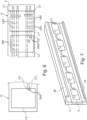
- such a circuit board 17 is shown as an example, which has conductor tracks on both sides. For reasons of clarity, only three of the five conductor loops L1 - L5 are shown. On the front side, the large-area conductor loops L1, L2 and L5 can be seen. On the back side, the closely spaced conductor tracks LB2 - LB5 of the respective loop connections C2 and C5 can be seen, which run along the length of the circuit board 17. The loop connections C1 run on the front. The loop connections C1 - C5 are all connected to the supply device 4.
- loop connections C2 and C5 end at the conductor loops L2 and L5, there are vias DK2 and DK5 from the front to the back, so that the conductor loops L2 and L5 are electrically connected to their loop connections C2 and C5.
- the supply device 4 indicated on the circuit board 17 can, for example, be mounted on the back of the circuit board 17.
- the electronic components of its electronics can also be soldered directly onto the circuit board 17.
- the Figure 7 shows finally a possibility of mechanically integrating the circuit board 17 into the shelf rail 3.
- the circuit board 17 forms part of the wall of a receiving shaft which serves to accommodate a number of shelf label displays 2.
- the receiving shaft has a recess corresponding to the thickness of the circuit board 17, into which the circuit board 17 is inserted so that its front side runs essentially flush with the rest of the wall of the receiving shaft.
- an upper guide strip 26 is formed at its upper end and a lower guide strip 27 at its lower end. These guide strips 26 and 27 can be bent upwards and downwards far enough for the shelf label display 2 to snap into place.
- the shelf label display 2 can be moved unhindered along the shelf rail 3 and positioned completely freely. Locating the power supply unit 4 on the rear side of the circuit board 17 is advantageous if the shelf label displays 2 are to be freely movable along the front side of the shelf rail 3, as is possible in the present case. In this case, the recess of the receiving slot must be adapted accordingly to accommodate the electronic components of the power supply unit 4.
- the Figure 8 shows a cross-sectional view of the shelf rail 3 with a conductor loop receptacle 28 on its rear side, wherein the conductor loop receptacle 28 is made directly from the material of the shelf rail 3 (i.e. from the plastic).
- the conductor loop receptacle 28 has a gap-shaped recess 29 into which a wire of the conductor loop L1 is immovably inserted.
- the gap-shaped recess 29 is flanked by two walls 30 which are dimensioned such that they create a snap mechanism that fixes the wire in its desired position.
- a band- or strip-shaped material 31 (band or strip of material) is inserted into the gap-shaped recess 29, which on the one hand presses the wire of the conductor loop L1 against the bottom of the recess 29 and on the other hand supports itself on a nose- or hook-like end of the outer wall 30 or engages there.
- the electronic supply device 4 is integrated into the shelf rail or attached to it. This allows a shelf rail with an individual electronic power supply to be realized.
- the supply device 4 can, for example, also be formed directly on the circuit board 17 or connected to it as a module or mechanically coupled as a module to the shelf rail 3 and electrically connected to the conductor loop L1 (to L5) of the shelf rail 3. This means that the shelf rail 3 can be transported as a whole, including its supply device 4, and easily put back into operation at another location.
Landscapes
- Engineering & Computer Science (AREA)
- Computer Networks & Wireless Communication (AREA)
- Physics & Mathematics (AREA)
- Power Engineering (AREA)
- General Physics & Mathematics (AREA)
- Signal Processing (AREA)
- Business, Economics & Management (AREA)
- Toxicology (AREA)
- Health & Medical Sciences (AREA)
- Theoretical Computer Science (AREA)
- Remote Sensing (AREA)
- Finance (AREA)
- Radar, Positioning & Navigation (AREA)
- Accounting & Taxation (AREA)
- Computer Vision & Pattern Recognition (AREA)
- Computer Security & Cryptography (AREA)
- Electromagnetism (AREA)
- General Health & Medical Sciences (AREA)
- Artificial Intelligence (AREA)
- General Business, Economics & Management (AREA)
- Strategic Management (AREA)
- Marketing (AREA)
- Economics (AREA)
- Development Economics (AREA)
- Cash Registers Or Receiving Machines (AREA)
- Display Racks (AREA)
- Warehouses Or Storage Devices (AREA)
Priority Applications (1)
| Application Number | Priority Date | Filing Date | Title |
|---|---|---|---|
| EP25162712.1A EP4550624A3 (fr) | 2019-06-14 | 2019-06-14 | Procédé de localisation d'une étiquette de rayon électronique |
Applications Claiming Priority (3)
| Application Number | Priority Date | Filing Date | Title |
|---|---|---|---|
| PCT/EP2019/065718 WO2020249232A1 (fr) | 2019-06-14 | 2019-06-14 | Procédé de localisation d'une étiquette électronique pour rayonnage |
| EP25162712.1A EP4550624A3 (fr) | 2019-06-14 | 2019-06-14 | Procédé de localisation d'une étiquette de rayon électronique |
| EP19733418.8A EP3984254B1 (fr) | 2019-06-14 | 2019-06-14 | Procede de localisation d'une etiquette electronique de rayonnage |
Related Parent Applications (1)
| Application Number | Title | Priority Date | Filing Date |
|---|---|---|---|
| EP19733418.8A Division EP3984254B1 (fr) | 2019-06-14 | 2019-06-14 | Procede de localisation d'une etiquette electronique de rayonnage |
Publications (2)
| Publication Number | Publication Date |
|---|---|
| EP4550624A2 true EP4550624A2 (fr) | 2025-05-07 |
| EP4550624A3 EP4550624A3 (fr) | 2025-07-09 |
Family
ID=67060371
Family Applications (2)
| Application Number | Title | Priority Date | Filing Date |
|---|---|---|---|
| EP19733418.8A Active EP3984254B1 (fr) | 2019-06-14 | 2019-06-14 | Procede de localisation d'une etiquette electronique de rayonnage |
| EP25162712.1A Pending EP4550624A3 (fr) | 2019-06-14 | 2019-06-14 | Procédé de localisation d'une étiquette de rayon électronique |
Family Applications Before (1)
| Application Number | Title | Priority Date | Filing Date |
|---|---|---|---|
| EP19733418.8A Active EP3984254B1 (fr) | 2019-06-14 | 2019-06-14 | Procede de localisation d'une etiquette electronique de rayonnage |
Country Status (4)
| Country | Link |
|---|---|
| US (1) | US11995500B2 (fr) |
| EP (2) | EP3984254B1 (fr) |
| CN (1) | CN113924787B (fr) |
| WO (1) | WO2020249232A1 (fr) |
Families Citing this family (3)
| Publication number | Priority date | Publication date | Assignee | Title |
|---|---|---|---|---|
| JP7514683B2 (ja) | 2020-07-28 | 2024-07-11 | 東芝テック株式会社 | 非接触給電装置 |
| WO2022218513A1 (fr) * | 2021-04-13 | 2022-10-20 | Ses-Imagotag Gmbh | Dispositif de support pour supporter un dispositif électronique à l'intérieur d'une zone de réception pour le dispositif de support |
| JP7739455B2 (ja) * | 2021-05-05 | 2025-09-16 | ヴジョングループ・ゲゼルシャフト・ミト・ベシュレンクテル・ハフツング | 棚レール装置の位置を特定するための方法及びシステム |
Citations (2)
| Publication number | Priority date | Publication date | Assignee | Title |
|---|---|---|---|---|
| WO2015124197A1 (fr) | 2014-02-20 | 2015-08-27 | Imagotag Gmbh | Système de communication par créneau temporel |
| WO2015172822A1 (fr) | 2014-05-14 | 2015-11-19 | Imagotag Gmbh | Procédé de localisation d'une étiquette rfid |
Family Cites Families (17)
| Publication number | Priority date | Publication date | Assignee | Title |
|---|---|---|---|---|
| US6409132B2 (en) * | 1999-04-30 | 2002-06-25 | Display Edge Technology, Ltd. | Attachment bracket for a rail |
| US6736316B2 (en) * | 2002-08-23 | 2004-05-18 | Yoram Neumark | Inventory control and indentification method |
| US20060163349A1 (en) * | 2004-09-30 | 2006-07-27 | W5 Networks, Inc. | Wireless systems suitable for retail automation and promotion |
| US20070013479A1 (en) * | 2004-12-20 | 2007-01-18 | Anurag Goel | Display designs and auxiliary promotional mechanisms for electronic labels |
| GB2481851A (en) * | 2010-07-09 | 2012-01-11 | Univ Antwerpen | Object location |
| KR101765916B1 (ko) * | 2010-12-31 | 2017-08-23 | 엘지이노텍 주식회사 | 전자 선반 라벨 및 배터리 잔량 관리 방법 |
| KR101434060B1 (ko) * | 2012-12-28 | 2014-08-25 | 삼성전기주식회사 | 전자 선반 시스템 |
| SG11201505404PA (en) * | 2013-01-11 | 2015-08-28 | Tagnetics Inc | Out of stock sensor |
| US9911138B2 (en) * | 2013-04-19 | 2018-03-06 | Wal-Mart Stores, Inc. | Automated limited-time retail merchandise promotion system |
| KR102062546B1 (ko) * | 2013-12-13 | 2020-01-06 | 주식회사 위츠 | 전자 태그 무선 충전 시스템, 및 전자 라벨 시스템 |
| KR20150122040A (ko) * | 2014-04-22 | 2015-10-30 | 삼성전기주식회사 | Nfc 기능이 내장된 전자 가격 표시기 |
| US9852468B2 (en) * | 2014-07-29 | 2017-12-26 | Trius Retail LLC | Electronic shelf system with mobile device interactivity and printed plastic display |
| WO2016187001A1 (fr) * | 2015-05-15 | 2016-11-24 | Rtc Industries, Inc. | Systèmes et procédés destinés à des dispositifs d'affichage électroniques de commercialisation |
| FR3055972B1 (fr) * | 2016-09-09 | 2019-08-16 | Store Electronic Systems | Localisation d'etiquettes electroniques de gondole dans une surface de vente |
| KR20180070861A (ko) * | 2016-12-19 | 2018-06-27 | 엘지이노텍 주식회사 | 위치 정보 단말기, 전자 가격 표시기 및 그의 동작 방법 |
| CN107414781A (zh) * | 2017-05-19 | 2017-12-01 | 重庆交通大学 | 超市购物智能机器人 |
| JP7555035B2 (ja) * | 2020-08-26 | 2024-09-24 | パナソニックIpマネジメント株式会社 | 業務支援装置、業務支援方法、及び、コンピュータプログラム |
-
2019
- 2019-06-14 WO PCT/EP2019/065718 patent/WO2020249232A1/fr not_active Ceased
- 2019-06-14 EP EP19733418.8A patent/EP3984254B1/fr active Active
- 2019-06-14 EP EP25162712.1A patent/EP4550624A3/fr active Pending
- 2019-06-14 CN CN201980097481.3A patent/CN113924787B/zh active Active
- 2019-06-14 US US17/617,686 patent/US11995500B2/en active Active
Patent Citations (2)
| Publication number | Priority date | Publication date | Assignee | Title |
|---|---|---|---|---|
| WO2015124197A1 (fr) | 2014-02-20 | 2015-08-27 | Imagotag Gmbh | Système de communication par créneau temporel |
| WO2015172822A1 (fr) | 2014-05-14 | 2015-11-19 | Imagotag Gmbh | Procédé de localisation d'une étiquette rfid |
Also Published As
| Publication number | Publication date |
|---|---|
| US20220237392A1 (en) | 2022-07-28 |
| US11995500B2 (en) | 2024-05-28 |
| CN113924787A (zh) | 2022-01-11 |
| EP4550624A3 (fr) | 2025-07-09 |
| EP3984254C0 (fr) | 2025-03-12 |
| EP3984254A1 (fr) | 2022-04-20 |
| EP3984254B1 (fr) | 2025-03-12 |
| CN113924787B (zh) | 2025-05-23 |
| WO2020249232A1 (fr) | 2020-12-17 |
Similar Documents
| Publication | Publication Date | Title |
|---|---|---|
| EP4018355B1 (fr) | Système d'étiquetage électronique des étagères avec sous-système de rails d'étagères | |
| EP3984254B1 (fr) | Procede de localisation d'une etiquette electronique de rayonnage | |
| EP3178043B1 (fr) | Système d'éclairage d'étagère et procédé servant à localiser des marchandises et à gérer des informations de prix | |
| EP1415263A2 (fr) | Procede de transmission de donnees entre un appareil de lecture/d'ecriture et une memoire de donnees, application d'un procede dans un systeme d'identification, appareil de lecture/d'ecriture et memoire de donnees mobile pour un tel systeme d'identification | |
| EP3984259B1 (fr) | Système d'étiquetage électronique des étagères avec sous-système de rails d'étagères | |
| EP3984288B1 (fr) | Système d'étiquetage électronique pour étagères avec protocole de communication radio standardisé | |
| WO2008134991A1 (fr) | Procédé d'établissement d'une liaison de communication sans fil entre un composant d'automatisation et un terminal opérateur mobile | |
| WO2021129932A1 (fr) | Système d'étiquettes électroniques de rayonnage comprenant une alimentation électrique qui assure un fonctionnement longue durée de consommateurs d'une étiquette de rayonnage | |
| DE102006007780B4 (de) | Flächenverkleidungs-Anordnung und Verfahren zum Lokalisieren bzw. Leiten von beweglichen Objekten und/oder Personen auf einer Fläche mit Hilfe einer Flächenverkleidungs-Anordnung | |
| WO2017102178A1 (fr) | Procédé et système d'analyse d'un environnement d'un terminal mobile | |
| WO2021129933A1 (fr) | Système d'étiquettes électroniques de rayonnage à sous-système de rails de rayonnage | |
| DE102019133973A1 (de) | Systeme und verfahren zur verwaltung einer population von rfid-etiketten | |
| EP3528187A1 (fr) | Procédé d'identification d'un objet et de fourniture des informations | |
| EP3983944B1 (fr) | Système électronique d'étiquettes de rayons à alimentation en énergie | |
| DE102011075372A1 (de) | System für die erweiterte Informationsbereitstellung für Kunden in einem Verkaufsraum für Hausgeräte sowie zugehöriges Verfahren und Computerprogrammprodukt | |
| WO1997014107A1 (fr) | Systeme electronique d'indication de prix | |
| EP3392811B1 (fr) | Système et procédé de distribution des données à des appareils électroniques | |
| EP3991084B1 (fr) | Procédé et dispositif d'écriture de logiciel et/ou de micrologiciel dans un circuit intégré programmable | |
| EP2175401B1 (fr) | Transpondeur | |
| EP3483774A1 (fr) | Étagère ou armoire dotée d'au moins deux clayettes ainsi qu'ensemble d'étagère ou d'armoire doté d'au moins deux étagères ou armoires | |
| EP4335122A1 (fr) | Procédé et système de détermination de l'emplacement d'un équipement de bord d'étagère | |
| EP2660607B1 (fr) | Identification et localisation de récipients d'échantillons dotés de puces RFID | |
| EP3077954B1 (fr) | Dispositif de communication servant à identifier et/ou localiser un transpondeur rfid | |
| DE102009010857B4 (de) | Verfahren für eine elektronische Artikelortung | |
| DE202021004393U1 (de) | System zur Ortsbestimmung von Regalschienen-Equipment |
Legal Events
| Date | Code | Title | Description |
|---|---|---|---|
| PUAI | Public reference made under article 153(3) epc to a published international application that has entered the european phase |
Free format text: ORIGINAL CODE: 0009012 |
|
| STAA | Information on the status of an ep patent application or granted ep patent |
Free format text: STATUS: THE APPLICATION HAS BEEN PUBLISHED |
|
| AC | Divisional application: reference to earlier application |
Ref document number: 3984254 Country of ref document: EP Kind code of ref document: P |
|
| AK | Designated contracting states |
Kind code of ref document: A2 Designated state(s): AL AT BE BG CH CY CZ DE DK EE ES FI FR GB GR HR HU IE IS IT LI LT LU LV MC MK MT NL NO PL PT RO RS SE SI SK SM TR |
|
| REG | Reference to a national code |
Ref country code: DE Ref legal event code: R079 Free format text: PREVIOUS MAIN CLASS: H02J0050200000 Ipc: H04W0004020000 |
|
| PUAL | Search report despatched |
Free format text: ORIGINAL CODE: 0009013 |
|
| AK | Designated contracting states |
Kind code of ref document: A3 Designated state(s): AL AT BE BG CH CY CZ DE DK EE ES FI FR GB GR HR HU IE IS IT LI LT LU LV MC MK MT NL NO PL PT RO RS SE SI SK SM TR |
|
| RIC1 | Information provided on ipc code assigned before grant |
Ipc: H04W 4/80 20180101ALN20250530BHEP Ipc: H04W 4/38 20180101ALN20250530BHEP Ipc: H04W 4/33 20180101ALN20250530BHEP Ipc: H02J 50/90 20160101ALN20250530BHEP Ipc: H02J 50/80 20160101ALN20250530BHEP Ipc: H02J 50/40 20160101ALN20250530BHEP Ipc: G01S 1/02 20100101ALN20250530BHEP Ipc: G06Q 30/02 20230101ALN20250530BHEP Ipc: H02J 50/20 20160101ALI20250530BHEP Ipc: H02J 7/34 20060101ALI20250530BHEP Ipc: G06Q 30/06 20230101ALI20250530BHEP Ipc: G01S 5/02 20100101ALI20250530BHEP Ipc: G01S 1/04 20060101ALI20250530BHEP Ipc: H04W 4/029 20180101ALI20250530BHEP Ipc: H04W 4/021 20180101ALI20250530BHEP Ipc: H04W 4/02 20180101AFI20250530BHEP |
|
| STAA | Information on the status of an ep patent application or granted ep patent |
Free format text: STATUS: REQUEST FOR EXAMINATION WAS MADE |
|
| 17P | Request for examination filed |
Effective date: 20251223 |
|
| STAA | Information on the status of an ep patent application or granted ep patent |
Free format text: STATUS: EXAMINATION IS IN PROGRESS |