EP4483479B1 - Rotor pour une machine électrique - Google Patents
Rotor pour une machine électrique Download PDFInfo
- Publication number
- EP4483479B1 EP4483479B1 EP23705364.0A EP23705364A EP4483479B1 EP 4483479 B1 EP4483479 B1 EP 4483479B1 EP 23705364 A EP23705364 A EP 23705364A EP 4483479 B1 EP4483479 B1 EP 4483479B1
- Authority
- EP
- European Patent Office
- Prior art keywords
- rotor
- winding
- elements
- winding head
- sleeve
- Prior art date
- Legal status (The legal status is an assumption and is not a legal conclusion. Google has not performed a legal analysis and makes no representation as to the accuracy of the status listed.)
- Active
Links
Images

Classifications
-
- H—ELECTRICITY
- H02—GENERATION; CONVERSION OR DISTRIBUTION OF ELECTRIC POWER
- H02K—DYNAMO-ELECTRIC MACHINES
- H02K17/00—Asynchronous induction motors; Asynchronous induction generators
- H02K17/02—Asynchronous induction motors
- H02K17/22—Asynchronous induction motors having rotors with windings connected to slip-rings
-
- H—ELECTRICITY
- H02—GENERATION; CONVERSION OR DISTRIBUTION OF ELECTRIC POWER
- H02K—DYNAMO-ELECTRIC MACHINES
- H02K1/00—Details of the magnetic circuit
- H02K1/06—Details of the magnetic circuit characterised by the shape, form or construction
- H02K1/22—Rotating parts of the magnetic circuit
- H02K1/26—Rotor cores with slots for windings
-
- H—ELECTRICITY
- H02—GENERATION; CONVERSION OR DISTRIBUTION OF ELECTRIC POWER
- H02K—DYNAMO-ELECTRIC MACHINES
- H02K1/00—Details of the magnetic circuit
- H02K1/06—Details of the magnetic circuit characterised by the shape, form or construction
- H02K1/22—Rotating parts of the magnetic circuit
- H02K1/28—Means for mounting or fastening rotating magnetic parts on to, or to, the rotor structures
-
- H—ELECTRICITY
- H02—GENERATION; CONVERSION OR DISTRIBUTION OF ELECTRIC POWER
- H02K—DYNAMO-ELECTRIC MACHINES
- H02K3/00—Details of windings
- H02K3/46—Fastening of windings on the stator or rotor structure
- H02K3/50—Fastening of winding heads, equalising connectors, or connections thereto
- H02K3/51—Fastening of winding heads, equalising connectors, or connections thereto applicable to rotors only
Definitions
- the invention relates to a rotor for an electrical machine, in particular for a rotor-fed slip-ring rotor machine, such as those used for speed-controlled hydroelectric motor generators for pumped storage power plants.
- the DE 10 2010 020 415 A1 discloses a rotor suitable for a variable-speed hydroelectric motor generator.
- the rotor disclosed in this document comprises winding elements arranged in axially extending slots of a rotor body, a winding head arranged axially next to the rotor body, and a winding head support, wherein the winding head is connected to the winding head support via tension bolts.
- the tension bolts engage support bodies at their radially outer ends, which in turn rest on the winding elements in the area of the winding head. Each winding element is thus held in the area of a winding head by two tension bolts, each with a support body per tension bolt.
- the object of the invention is to provide an arrangement in which the said problem can be avoided.
- FIG. 1 shows a rotor according to the invention in a schematic representation.
- Figure 1 only a section of the rotor is shown.
- the rotor is designated 1.
- the rotor 1 comprises a rotor body, designated 2, and a plurality of winding elements which are arranged in axially extending slots of the rotor body 2.
- the winding elements form two layers in the radial direction.
- the winding elements protrude in the axial direction beyond the rotor body 2 and thus form a so-called winding head, which is arranged axially next to the rotor body 2.
- a winding element of one layer is connected at its end to the end of a winding element of the other layer.
- a winding element is designated 3.
- the winding head comprises a winding head carrier, which Figure 1 designated 4 and a plurality of holding elements, one of which is Figure 1 is designated 5.
- Each holding element 5 comprises a tension bolt and a support body.
- Figure 1 One of the tension bolts is designated 6, and one of the support bodies is designated 7.
- the support bodies 7 are arranged radially outside the winding elements 3.
- the tension bolts 6 each penetrate the corresponding support body 7 and are screwed into the winding head support 4 with a thread.
- the winding head support 4 can also consist of several parts, so that the tension bolts 6 are screwed, for example, into profile strips arranged in corresponding grooves in the winding head support body. The profile strips and winding head support bodies are then parts of the winding head support 4.
- the holding elements 5 comprise a stop surface 8, which is designed such that it can come into contact with the winding head carrier 4 when the tension bolts 6 are screwed in, in order to adjust the radial length by which the tension bolts 6 protrude from the winding head carrier 4 to a predefined dimension.
- the predefined dimension is dimensioned such that the support bodies 7 are not pressed against the winding elements 3 when the rotor 1 is at rest. This means that when the rotor 1 is at rest, the support bodies 7 ideally just touch the winding elements 3 when the tension bolts 6 are screwed into the winding head carrier 4 far enough that the stop surface 8 comes into contact with the winding head carrier 4.
- a (small) gap can also be present between the support body 7 and the winding elements 3 in the aforementioned position.
- the feature "that the support bodies 7 are not pressed against the winding elements 3 when the rotor 1 is at rest” is to be understood as meaning that the compressive force transmitted to the winding elements 3 by the tightened tie bolts 6 when the rotor 1 is at rest is negligibly small compared to the tensile force acting in the tightened tie bolts 6. This is the case when the compressive force transmitted to the winding elements 3 by a tightened tie bolt 6 is less than 15% of the tensile force acting in the respective tie bolt 6.
- the stop surfaces 8 thus formed prevent the winding elements 3 from being deformed when the tension bolts 6 are screwed in. On the other hand, they ensure that the screw connection between the tension bolts 6 and the winding head support 4 is clamped, so that the screw connection cannot come loose during operation of the rotor 1.
- a high preload of the tension bolts 6 also ensures that the additional force acting on the tension bolts 6 during operation is small compared to the preload force, thereby extending the service life of the tension bolts 6.
- the holding elements 5 may comprise an elastic element which is arranged in the space between the associated support body 7 and the winding elements 3 held by the respective holding element 5.
- an elastic element is designated 9.
- the elastic elements 9 are designed such that they are slightly compressed in the radial direction when the tension bolts 6 are screwed in until the associated stop surfaces 8 come into contact with the winding head carrier 4.
- the modulus of elasticity of the elastic elements 9 is to be selected such that the aforementioned compression of the elastic elements 9 does not lead to any significant deformation of the winding elements 3.
- the elastic elements 9 are designed such that no significant deformation of the winding elements 3 can occur when the tension bolts 6 are screwed in until the associated stop surfaces 8 come into contact with the winding head carrier 4.
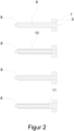
- FIG. 2 shows various embodiments of holding elements 5 according to the invention.
- the stop surface 8 is formed by a shoulder of the tension bolt 6.
- the holding element 5 comprises a sleeve, which is designated 10.
- the tension bolt 6 penetrates the sleeve 10, and the stop surface 8 is formed by the end of the sleeve 10, which is oriented towards the winding head carrier 4.
- the support body 7 comprises a sleeve-like protuberance, wherein the stop surface 8 is arranged at the end of the protuberance.
- the support bodies 7 are only partially arranged radially outside the winding elements 3, since the sleeve-shaped protuberance thereof protrudes between the winding elements 3.
- This protuberance can also serve to support the winding elements held by the respective holding element in the lateral direction.
- a further embodiment results from a combination of the last two embodiments, in that a shorter sleeve 10 is combined with a correspondingly shorter protrusion of the support body 7.
- the stop surface 8 is formed by the end of the sleeve 10.
- the tension bolt 6 comprises a shoulder, which is designated 11 and which presses against a sleeve 10 when screwed in.
- the stop surface 8 is also formed here by the end of the sleeve 10.
- This embodiment has the advantage that the support body 7 is largely relieved
- Further embodiments result from the use of several sleeves 10 per tension bolt 6, wherein the sleeves 10 are pressed against one another when the associated tension bolt 6 is screwed in.
Landscapes
- Engineering & Computer Science (AREA)
- Power Engineering (AREA)
- Insulation, Fastening Of Motor, Generator Windings (AREA)
Claims (6)
- Rotor (1) pour une machine électrique avec un corps de rotor (2), une pluralité d'éléments de bobinage (3) et une tête de bobinage disposée axialement à côté du corps de rotor (2), les éléments de bobinage (3) étant disposés dans des rainures s'étendant axialement du corps de rotor (2), et dans lequel la tête d'enroulement comprend un support de tête d'enroulement (4) et une pluralité d'éléments de retenue (5), et dans lequel chaque élément de retenue (5) comprend respectivement un boulon de traction (6) et un corps de support (7), et dans lequel les corps de support (7) sont disposés au moins partiellement dans la direction radiale à l'extérieur des éléments d'enroulement (3), et les boulons de traction (6) traversant chacun le corps d'appui (7) correspondant et étant vissés avec un filetage dans le support de tête d'enroulement (4), caractérisé en ce que les éléments de retenue (5) comprennent chacun une surface de butée (8) qui est conçue de telle sorte qu'elle peut venir en appui sur le support de tête d'enroulement (4) lors du vissage des boulons de traction (7), pour régler ainsi à une mesure prédéfinie la longueur radiale avec laquelle les boulons de traction (6) dépassent du support de tête d'enroulement (4), la mesure prédéfinie étant dimensionnée de telle sorte que les corps d'appui (7) ne sont pas pressés contre les éléments d'enroulement (3) dans la position de repos du rotor (1).
- Rotor (1) selon la revendication 1, et dans lequel un élément de retenue (5) comprend un élément élastique (9) qui est disposé dans un espace intermédiaire entre le corps de support associé (7) et les éléments d'enroulement (3) retenus par l'élément de retenue.
- Rotor (1) selon la revendication 1 ou 2, et dans lequel une surface de butée (8) est formée par un épaulement du boulon de traction (6).
- Rotor (1) selon la revendication 1 ou 2, et dans lequel un élément de retenue (5) comprend un manchon (10), et dans lequel le boulon de traction (6) traverse le manchon (10), et dans lequel la surface de butée (8) est formée par l'extrémité du manchon (10), qui est disposée en étant orientée vers le support de tête d'enroulement (4).
- Rotor (1) selon la revendication 4, dans lequel le boulon de traction (6) comprend un épaulement (11) qui peut être pressé contre le manchon (10) lors du serrage du boulon de traction (6).
- Rotor (1) selon la revendication 1 ou 2, et dans lequel un corps de support (7) comprend une protubérance en forme de manchon, et dans lequel la surface de butée (8) est disposée à l'extrémité de la protubérance.
Applications Claiming Priority (2)
| Application Number | Priority Date | Filing Date | Title |
|---|---|---|---|
| DE102022103999 | 2022-02-21 | ||
| PCT/EP2023/053591 WO2023156370A1 (fr) | 2022-02-21 | 2023-02-14 | Rotor pour une machine électrique |
Publications (2)
| Publication Number | Publication Date |
|---|---|
| EP4483479A1 EP4483479A1 (fr) | 2025-01-01 |
| EP4483479B1 true EP4483479B1 (fr) | 2025-04-30 |
Family
ID=85251660
Family Applications (1)
| Application Number | Title | Priority Date | Filing Date |
|---|---|---|---|
| EP23705364.0A Active EP4483479B1 (fr) | 2022-02-21 | 2023-02-14 | Rotor pour une machine électrique |
Country Status (5)
| Country | Link |
|---|---|
| US (1) | US20240413695A1 (fr) |
| EP (1) | EP4483479B1 (fr) |
| CN (1) | CN118525438A (fr) |
| CA (1) | CA3244759A1 (fr) |
| WO (1) | WO2023156370A1 (fr) |
Family Cites Families (4)
| Publication number | Priority date | Publication date | Assignee | Title |
|---|---|---|---|---|
| DE701612C (de) * | 1937-08-20 | 1941-01-20 | Siemens Schuckertwerke Akt Ges | Spulenkopfbefestigung fuer Laeuferwicklungen elektrischer Maschinen |
| DE19519127C1 (de) * | 1995-05-16 | 1996-09-12 | Siemens Ag | Dynamoelektrische Maschine mit bewickeltem Rotor |
| DE102010020415A1 (de) | 2010-05-12 | 2011-11-17 | Voith Patent Gmbh | Rotor für eine dynamoelektrische Maschine |
| CN204243955U (zh) * | 2014-09-16 | 2015-04-01 | 哈尔滨电机厂有限责任公司 | 水轮发电机转子引线固定装置 |
-
2023
- 2023-02-14 WO PCT/EP2023/053591 patent/WO2023156370A1/fr not_active Ceased
- 2023-02-14 EP EP23705364.0A patent/EP4483479B1/fr active Active
- 2023-02-14 CN CN202380016248.4A patent/CN118525438A/zh active Pending
- 2023-02-14 CA CA3244759A patent/CA3244759A1/fr active Pending
-
2024
- 2024-08-20 US US18/809,813 patent/US20240413695A1/en active Pending
Also Published As
| Publication number | Publication date |
|---|---|
| EP4483479A1 (fr) | 2025-01-01 |
| CA3244759A1 (fr) | 2025-01-20 |
| CN118525438A (zh) | 2024-08-20 |
| WO2023156370A1 (fr) | 2023-08-24 |
| US20240413695A1 (en) | 2024-12-12 |
Similar Documents
| Publication | Publication Date | Title |
|---|---|---|
| EP2790299B1 (fr) | Ensemble de noyau statorique | |
| DE102004030830B4 (de) | Bremsenaufbau für eine Traktionsmaschine | |
| EP0669694A1 (fr) | Dispositif de fixation des extrémités de bobinage d'un enroulement statorique dans une machine dynamoélectrique | |
| DE102009057782A1 (de) | Stator für rotierende elektrische Maschine | |
| EP2685607A1 (fr) | Fixation d'aimants permanents sur un rotor | |
| EP0171571A1 (fr) | Corps de stator à plaques de pression lamellées | |
| DE10230158B4 (de) | Klemm-Mechanismus für eine Lenksäule | |
| EP2630702B1 (fr) | Balai de charbon comportant un dispositif de coupure | |
| EP4483479B1 (fr) | Rotor pour une machine électrique | |
| DE102007050803A1 (de) | Bürstenvorrichtung mit einer Feder für eine Elektromaschine | |
| EP4483476B1 (fr) | Support de tête de bobinage d'un rotor pour une machine électrique | |
| DE19927279B4 (de) | Käfigläufer für eine elektrische Maschine | |
| DE102008064500A1 (de) | Elektrische Maschine mit Abstützung der Wicklungsschaltung am Statorblechpaket | |
| EP4456389A1 (fr) | Dispositif et procédé de fixation d'un ensemble d'enroulement | |
| WO2021004676A1 (fr) | Rotor pour une machine électrique | |
| DE10310306A1 (de) | Vorrichtung zum Spannen einer Statorwicklung | |
| DE102018213128A1 (de) | Gehäuseanordnung eines Elektromotors | |
| DE102019218196A1 (de) | Elektromotorisch angetriebenes Aggregat für ein Fahrzeug | |
| AT525718A1 (de) | Rotor | |
| DE9416348U1 (de) | Wellenverbindung für einen Stromerzeuger | |
| EP1798417B1 (fr) | Pompe à vide | |
| WO2021004675A1 (fr) | Rotor pour une machine électrique | |
| DE102019213574A1 (de) | Rotor einer elektrischen Maschine | |
| EP3690902B1 (fr) | Dispositif de pressage d'un bloc comportant un ou une pluralité d'enroulements d'une machine électrique statique | |
| DE102024129093A1 (de) | Rotor für eine Axialflussmaschine, Axialflussmaschine mit einem Rotor sowie Kraftfahrzeug mit einer Axialflussmaschine |
Legal Events
| Date | Code | Title | Description |
|---|---|---|---|
| STAA | Information on the status of an ep patent application or granted ep patent |
Free format text: STATUS: UNKNOWN |
|
| STAA | Information on the status of an ep patent application or granted ep patent |
Free format text: STATUS: THE INTERNATIONAL PUBLICATION HAS BEEN MADE |
|
| PUAI | Public reference made under article 153(3) epc to a published international application that has entered the european phase |
Free format text: ORIGINAL CODE: 0009012 |
|
| STAA | Information on the status of an ep patent application or granted ep patent |
Free format text: STATUS: REQUEST FOR EXAMINATION WAS MADE |
|
| 17P | Request for examination filed |
Effective date: 20240923 |
|
| AK | Designated contracting states |
Kind code of ref document: A1 Designated state(s): AL AT BE BG CH CY CZ DE DK EE ES FI FR GB GR HR HU IE IS IT LI LT LU LV MC ME MK MT NL NO PL PT RO RS SE SI SK SM TR |
|
| GRAP | Despatch of communication of intention to grant a patent |
Free format text: ORIGINAL CODE: EPIDOSNIGR1 |
|
| STAA | Information on the status of an ep patent application or granted ep patent |
Free format text: STATUS: GRANT OF PATENT IS INTENDED |
|
| GRAS | Grant fee paid |
Free format text: ORIGINAL CODE: EPIDOSNIGR3 |
|
| GRAA | (expected) grant |
Free format text: ORIGINAL CODE: 0009210 |
|
| STAA | Information on the status of an ep patent application or granted ep patent |
Free format text: STATUS: THE PATENT HAS BEEN GRANTED |
|
| DAV | Request for validation of the european patent (deleted) | ||
| DAX | Request for extension of the european patent (deleted) | ||
| INTG | Intention to grant announced |
Effective date: 20250317 |
|
| AK | Designated contracting states |
Kind code of ref document: B1 Designated state(s): AL AT BE BG CH CY CZ DE DK EE ES FI FR GB GR HR HU IE IS IT LI LT LU LV MC ME MK MT NL NO PL PT RO RS SE SI SK SM TR |
|
| REG | Reference to a national code |
Ref country code: CH Ref legal event code: EP Ref country code: GB Ref legal event code: FG4D Free format text: NOT ENGLISH |
|
| REG | Reference to a national code |
Ref country code: DE Ref legal event code: R096 Ref document number: 502023000914 Country of ref document: DE |
|
| REG | Reference to a national code |
Ref country code: IE Ref legal event code: FG4D Free format text: LANGUAGE OF EP DOCUMENT: GERMAN |
|
| REG | Reference to a national code |
Ref country code: NL Ref legal event code: MP Effective date: 20250430 |
|
| PG25 | Lapsed in a contracting state [announced via postgrant information from national office to epo] |
Ref country code: FI Free format text: LAPSE BECAUSE OF FAILURE TO SUBMIT A TRANSLATION OF THE DESCRIPTION OR TO PAY THE FEE WITHIN THE PRESCRIBED TIME-LIMIT Effective date: 20250430 Ref country code: ES Free format text: LAPSE BECAUSE OF FAILURE TO SUBMIT A TRANSLATION OF THE DESCRIPTION OR TO PAY THE FEE WITHIN THE PRESCRIBED TIME-LIMIT Effective date: 20250430 Ref country code: PT Free format text: LAPSE BECAUSE OF FAILURE TO SUBMIT A TRANSLATION OF THE DESCRIPTION OR TO PAY THE FEE WITHIN THE PRESCRIBED TIME-LIMIT Effective date: 20250901 |
|
| REG | Reference to a national code |
Ref country code: LT Ref legal event code: MG9D |
|
| PG25 | Lapsed in a contracting state [announced via postgrant information from national office to epo] |
Ref country code: NO Free format text: LAPSE BECAUSE OF FAILURE TO SUBMIT A TRANSLATION OF THE DESCRIPTION OR TO PAY THE FEE WITHIN THE PRESCRIBED TIME-LIMIT Effective date: 20250730 Ref country code: GR Free format text: LAPSE BECAUSE OF FAILURE TO SUBMIT A TRANSLATION OF THE DESCRIPTION OR TO PAY THE FEE WITHIN THE PRESCRIBED TIME-LIMIT Effective date: 20250731 |
|
| PG25 | Lapsed in a contracting state [announced via postgrant information from national office to epo] |
Ref country code: PL Free format text: LAPSE BECAUSE OF FAILURE TO SUBMIT A TRANSLATION OF THE DESCRIPTION OR TO PAY THE FEE WITHIN THE PRESCRIBED TIME-LIMIT Effective date: 20250430 Ref country code: NL Free format text: LAPSE BECAUSE OF FAILURE TO SUBMIT A TRANSLATION OF THE DESCRIPTION OR TO PAY THE FEE WITHIN THE PRESCRIBED TIME-LIMIT Effective date: 20250430 |
|
| PG25 | Lapsed in a contracting state [announced via postgrant information from national office to epo] |
Ref country code: BG Free format text: LAPSE BECAUSE OF FAILURE TO SUBMIT A TRANSLATION OF THE DESCRIPTION OR TO PAY THE FEE WITHIN THE PRESCRIBED TIME-LIMIT Effective date: 20250430 |
|
| PG25 | Lapsed in a contracting state [announced via postgrant information from national office to epo] |
Ref country code: HR Free format text: LAPSE BECAUSE OF FAILURE TO SUBMIT A TRANSLATION OF THE DESCRIPTION OR TO PAY THE FEE WITHIN THE PRESCRIBED TIME-LIMIT Effective date: 20250430 |
|
| PG25 | Lapsed in a contracting state [announced via postgrant information from national office to epo] |
Ref country code: RS Free format text: LAPSE BECAUSE OF FAILURE TO SUBMIT A TRANSLATION OF THE DESCRIPTION OR TO PAY THE FEE WITHIN THE PRESCRIBED TIME-LIMIT Effective date: 20250731 |
|
| PG25 | Lapsed in a contracting state [announced via postgrant information from national office to epo] |
Ref country code: IS Free format text: LAPSE BECAUSE OF FAILURE TO SUBMIT A TRANSLATION OF THE DESCRIPTION OR TO PAY THE FEE WITHIN THE PRESCRIBED TIME-LIMIT Effective date: 20250830 |
|
| PG25 | Lapsed in a contracting state [announced via postgrant information from national office to epo] |
Ref country code: LV Free format text: LAPSE BECAUSE OF FAILURE TO SUBMIT A TRANSLATION OF THE DESCRIPTION OR TO PAY THE FEE WITHIN THE PRESCRIBED TIME-LIMIT Effective date: 20250430 |
|
| PG25 | Lapsed in a contracting state [announced via postgrant information from national office to epo] |
Ref country code: DK Free format text: LAPSE BECAUSE OF FAILURE TO SUBMIT A TRANSLATION OF THE DESCRIPTION OR TO PAY THE FEE WITHIN THE PRESCRIBED TIME-LIMIT Effective date: 20250430 Ref country code: SM Free format text: LAPSE BECAUSE OF FAILURE TO SUBMIT A TRANSLATION OF THE DESCRIPTION OR TO PAY THE FEE WITHIN THE PRESCRIBED TIME-LIMIT Effective date: 20250430 |
|
| PG25 | Lapsed in a contracting state [announced via postgrant information from national office to epo] |
Ref country code: CZ Free format text: LAPSE BECAUSE OF FAILURE TO SUBMIT A TRANSLATION OF THE DESCRIPTION OR TO PAY THE FEE WITHIN THE PRESCRIBED TIME-LIMIT Effective date: 20250430 |
|
| PG25 | Lapsed in a contracting state [announced via postgrant information from national office to epo] |
Ref country code: EE Free format text: LAPSE BECAUSE OF FAILURE TO SUBMIT A TRANSLATION OF THE DESCRIPTION OR TO PAY THE FEE WITHIN THE PRESCRIBED TIME-LIMIT Effective date: 20250430 |
|
| PG25 | Lapsed in a contracting state [announced via postgrant information from national office to epo] |
Ref country code: SK Free format text: LAPSE BECAUSE OF FAILURE TO SUBMIT A TRANSLATION OF THE DESCRIPTION OR TO PAY THE FEE WITHIN THE PRESCRIBED TIME-LIMIT Effective date: 20250430 |
|
| PG25 | Lapsed in a contracting state [announced via postgrant information from national office to epo] |
Ref country code: IT Free format text: LAPSE BECAUSE OF FAILURE TO SUBMIT A TRANSLATION OF THE DESCRIPTION OR TO PAY THE FEE WITHIN THE PRESCRIBED TIME-LIMIT Effective date: 20250430 |
|
| REG | Reference to a national code |
Ref country code: DE Ref legal event code: R097 Ref document number: 502023000914 Country of ref document: DE |
|
| REG | Reference to a national code |
Ref country code: CH Ref legal event code: U11 Free format text: ST27 STATUS EVENT CODE: U-0-0-U10-U11 (AS PROVIDED BY THE NATIONAL OFFICE) Effective date: 20260301 |
|
| PLBE | No opposition filed within time limit |
Free format text: ORIGINAL CODE: 0009261 |
|
| STAA | Information on the status of an ep patent application or granted ep patent |
Free format text: STATUS: NO OPPOSITION FILED WITHIN TIME LIMIT |
|
| REG | Reference to a national code |
Ref country code: CH Ref legal event code: L10 Free format text: ST27 STATUS EVENT CODE: U-0-0-L10-L00 (AS PROVIDED BY THE NATIONAL OFFICE) Effective date: 20260311 |
|
| 26N | No opposition filed |
Effective date: 20260202 |
|
| PGFP | Annual fee paid to national office [announced via postgrant information from national office to epo] |
Ref country code: DE Payment date: 20260218 Year of fee payment: 4 |
|
| PGFP | Annual fee paid to national office [announced via postgrant information from national office to epo] |
Ref country code: AT Payment date: 20260301 Year of fee payment: 4 |
|
| PGFP | Annual fee paid to national office [announced via postgrant information from national office to epo] |
Ref country code: FR Payment date: 20260219 Year of fee payment: 4 |