EP4483976A1 - Planche de glisse - Google Patents
Planche de glisse Download PDFInfo
- Publication number
- EP4483976A1 EP4483976A1 EP24184179.0A EP24184179A EP4483976A1 EP 4483976 A1 EP4483976 A1 EP 4483976A1 EP 24184179 A EP24184179 A EP 24184179A EP 4483976 A1 EP4483976 A1 EP 4483976A1
- Authority
- EP
- European Patent Office
- Prior art keywords
- sliding board
- snowboard
- handle
- handrail
- posts
- Prior art date
- Legal status (The legal status is an assumption and is not a legal conclusion. Google has not performed a legal analysis and makes no representation as to the accuracy of the status listed.)
- Withdrawn
Links
Images
Classifications
-
- A—HUMAN NECESSITIES
- A63—SPORTS; GAMES; AMUSEMENTS
- A63C—SKATES; SKIS; ROLLER SKATES; DESIGN OR LAYOUT OF COURTS, RINKS OR THE LIKE
- A63C5/00—Skis or snowboards
- A63C5/03—Mono skis; Snowboards
-
- A—HUMAN NECESSITIES
- A63—SPORTS; GAMES; AMUSEMENTS
- A63C—SKATES; SKIS; ROLLER SKATES; DESIGN OR LAYOUT OF COURTS, RINKS OR THE LIKE
- A63C10/00—Snowboard bindings
- A63C10/28—Snowboard bindings characterised by auxiliary devices or arrangements on the bindings
- A63C10/285—Pads as foot or binding supports, e.g. pads made of foam
-
- A—HUMAN NECESSITIES
- A63—SPORTS; GAMES; AMUSEMENTS
- A63C—SKATES; SKIS; ROLLER SKATES; DESIGN OR LAYOUT OF COURTS, RINKS OR THE LIKE
- A63C5/00—Skis or snowboards
- A63C5/06—Skis or snowboards with special devices thereon, e.g. steering devices
-
- A—HUMAN NECESSITIES
- A63—SPORTS; GAMES; AMUSEMENTS
- A63C—SKATES; SKIS; ROLLER SKATES; DESIGN OR LAYOUT OF COURTS, RINKS OR THE LIKE
- A63C5/00—Skis or snowboards
- A63C5/16—Devices enabling skis to be used whilst held in a particular configuration with respect to each other, e.g. for training purposes
-
- A—HUMAN NECESSITIES
- A63—SPORTS; GAMES; AMUSEMENTS
- A63C—SKATES; SKIS; ROLLER SKATES; DESIGN OR LAYOUT OF COURTS, RINKS OR THE LIKE
- A63C2201/00—Use of skates, skis, roller-skates, snowboards and courts
- A63C2201/12—Tandem riding
Definitions
- the present application relates to a snowboard.
- This is a winter sports device used primarily for snowboarding. It typically comprises a flat sliding board that may have metal edges on its underside and often a slight curvature (camber or rocker) to improve maneuverability and grip in the snow.
- the snowboard is typically complemented by boot bindings that securely fasten the rider's snowboard boots and allow different positions to support different riding styles.
- Snowboards are used in ski resorts on groomed slopes, in the fun park for jumps and tricks, and in the backcountry for deep snow descents.
- Snowboards of the type described above are already known in the state of the art.
- the snowboard is equipped with a lever that is attached to the snowboard's sliding board.
- This lever is designed to be pivotable in a plane that is oriented perpendicular to the longitudinal axis of the sliding board.
- the lever is arranged between the legs of the person using the snowboard, so that a fastening point of the lever is located between the feet of the person using the snowboard.
- a design is disclosed in which the snowboard is equipped with a U-shaped lever. This lever extends between opposite end regions of the sliding board, so that the feet of the person using the snowboard are positioned between the end fastening points of the lever.
- Snowboards such as the one described above are neither designed nor suitable for accompanied snowboarding. Particularly for families or as part of a childcare program for young children, it would be desirable to design a snowboard in such a way that it can be used jointly by an adult and a child.
- the present application is therefore based on the object of providing a snowboard that can be used jointly by an adult and a child.
- the snowboard comprises a sliding board and at least two shoe bindings arranged on the sliding board.
- the latter are designed and configured to hold the shoes of a person using the snowboard, whereby a force-transmitting connection is established between the shoes (and thus the body) of the person using the snowboard and the sliding board by means of the shoe bindings.
- the snowboard also includes a handle that is attached to the sliding board.
- This handle has a U-shaped holding part and is attached to the sliding board at two fastening points arranged one behind the other when viewed in the longitudinal direction of the sliding board. In this way, forces acting on the handle can be diverted into the sliding board.
- the handle is rigidly connected to the sliding board.
- the handle can be formed, for example, from a metal tube construction, whereby the handle can be either made in one piece or composed of several parts. A design made of plastic or composite materials is also conceivable.
- the "U" formed by the holding part is upside down or turned over when the snowboard is used as intended, in which the underside of the sliding board rests on the ground (snow).
- the U-shaped holding part has two posts and a handrail connecting the posts.
- the posts which are preferably formed from round tubes, extend from opposite ends of the handrail so that the posts together with the handrail form the U-shape.
- the handrail extends at a distance above the sliding board.
- the handrail bridges from the upper end of one post to the upper end of the other post in a direction parallel to a longitudinal axis of the sliding board. In other words, the U formed by the holding part is aligned parallel to the longitudinal direction of the sliding board and upside down.
- the handrail in the sense of the present application is, for example, and preferably oriented parallel to a longitudinal axis of the sliding board. This means that two hands of a child grasping the handrail can grasp the handrail one after the other in the longitudinal direction of the sliding board.
- the fact that the handrail is oriented parallel to the longitudinal axis of the sliding board also includes, in the sense of the present application, that the handrail is between the two upper ends of one and the other post can run in different ways.
- the handrail connects the two upper ends in a straight line (and thus extends parallel to the longitudinal axis of the sliding board)
- a connecting line between the two ends of the posts runs parallel to the longitudinal axis of the sliding board.
- the snowboard is characterized by the fact that the handle is rigidly connected to the sliding board, so that it is suitable for absorbing the holding forces of a person using the snowboard and for transferring these holding forces to the sliding board.
- "Rigid” here means that the handle cannot move relative to the sliding board when the snowboard is used as intended, neither translationally nor rotationally.
- This means that the handle is suitable for a child standing on the sliding board to hold on to the handle, while an adult standing on the same board can take over the typical control of the snowboard.
- the child is to be understood as a kind of "passenger” on the sliding board, namely under the guidance and control of the sliding board by the adult.
- the handle is positioned between the shoe bindings intended for the adult's shoes. Accordingly, the two fastening points of the handle, with which the handle is attached to the sliding board, are positioned between the shoe bindings when viewed in the longitudinal direction of the sliding board. In this way, the child can stand between the adult's legs on the sliding board and grasp the handle located there and hold on to it.
- the handle is also shaped in such a way that the handrail, which is intended for the child to grasp, is arranged off-center in the width direction of the sliding board.
- the handrail can run at least essentially in the vertical direction with respect to the sliding board, in alignment with a side edge of the sliding board, when viewed in the width direction.
- the child can stand transversely to the longitudinal axis of the sliding board, approximately in the middle of the sliding board between the fastening points of the handle, and can hold the handrail of the handle with its front with arms bent.
- the holding part is therefore positioned in front of the child's upper body when the child is standing on the sliding board.
- the handrail is associated with the side edge of the sliding board or is aligned with the side edge at least substantially in the vertical direction relative to the sliding board, towards which the shoe bindings are directed.
- the adult person whose shoes interact with the shoe bindings stands in the direction of the handle and the handrail, so that the tips of the shoes or feet point in the direction of the side edge with which the handrail is aligned in the manner described.
- the handle is designed and constructed to serve a person using the snowboard (especially a child) so that the person can hold on to the handle, thereby making it easier to stand on the board.
- the handrail provides a comfortable and safe grip, it can be made of an ergonomically shaped plastic that provides appropriate grip recesses for the hand of each child, specifying an optimal grip position.
- the snowboard according to the invention has many advantages.
- it allows a child to ride on the sliding board together with an adult, for example a parent or guardian, with the adult standing up on the sliding board with their legs apart in the usual way and using the shoe bindings to connect to the sliding board.
- the handle and the child are positioned between the legs or between the shoe bindings of the adult on the sliding board, so that neither the child nor the handle hinder the adult's activity and the child can hold on to the rigid handle.
- the child has a secure footing on the sliding board, so that the adult and the child can use the snowboard together.
- a corresponding usage situation is also shown as an example in the embodiment below.
- the handle can be easily retrofitted to most commercially available snowboards, so that the respective snowboard is converted into one with a handle.
- the snowboard comprises, in addition to the shoe bindings for the adult, two additional auxiliary shoe bindings for the child arranged on the gliding board.
- the auxiliary shoe bindings which are generally smaller than the other shoe bindings, are located accordingly between the Attachment points of the handle. It is important that the shoe bindings and the auxiliary shoe bindings are aligned in the same way, i.e. the feet of the adult and the child point towards the same side edge of the same board when the shoe bindings and the auxiliary shoe bindings are used at the same time. This means that the upper bodies of the adult and the child are aligned in the same way towards the same side of the snowboard when the adult and the child are standing on the gliding board and are connected to it using the shoe bindings or the auxiliary shoe bindings.
- the snowboard has an anti-slip coating that is arranged between the fastening points of the handle.
- This anti-slip coating allows the child to stand on it with his shoes on, whereby friction between the child's shoes and the sliding board is greatly increased by the anti-slip coating. In this way, forces can be introduced from the child's shoes into the sliding board that are oriented parallel to a standing surface of the sliding board.
- the arrangement of auxiliary shoe bindings can preferably be dispensed with.
- An anti-slip coating can, for example and preferably, be formed from an elastomeric material.
- the handle has two fastening parts by means of which it is fastened to the sliding board.
- the fastening parts can in particular each be connected to one of the posts of the U-shaped holding part, wherein a respective fastening part preferably extends from a lower end of an associated post that is arranged opposite the handrail.
- the fastening parts preferably extend from the lower end of the respective associated post in the transverse direction of the sliding board.
- the fastening parts are preferably oriented parallel to one another.
- the handle is further preferably designed such that the fastening parts each extend at an angle to the U-shaped holding part that is between 70° and 90°, preferably between 75° and 85°. In this way, the fastening parts together with the posts each form an L-shape when viewed from a side view of the holding part or a front view of the snowboard.
- This design has the advantage that the handle can be attached to the sliding board by means of the fastening parts, for example by means of one or more fastening means per fastening part, but the U-shaped holding part is nevertheless located laterally in the area of a side edge of the sliding board approximately vertically to the standing surface of the sliding board.
- the handrail in the manner described above off-center, i.e. laterally offset in the area of a side edge of the sliding board when viewed in the width direction of the sliding board, while the fastening of the handle can nevertheless take place in a central area of the sliding board when viewed in the width direction of the sliding board, into which the fastening parts extend starting from the lower ends of the posts.
- a corresponding design can also be seen in the exemplary embodiment below.
- the posts of the holding part or their longitudinal axes each extend at an angle between 70° and 90°, preferably between 75° and 85°, relative to an upper standing surface of the sliding board. This is equivalent to a slight inclination of the posts relative to a vertical that extends vertically to the standing surface of the sliding board.
- this slight inclination of the posts relative to the vertical offers the advantage that a horizontal offset is generated over the length of the posts, starting from their lower ends associated with the sliding board to their upper ends facing away from the sliding board, which can contribute to a handrail extending between the upper ends of the posts being arranged laterally relative to the sliding board when viewed in the width direction of the sliding board, for example and preferably at least substantially in vertical alignment with a side edge of the sliding board.
- the handle is equipped with the described fastening parts, it is also advantageous if these are each elongated and extend perpendicular to the longitudinal axis of the sliding board, i.e. in the transverse direction of the sliding board.
- the fastening parts are connected to the sliding board by means of at least one, preferably several, fastening means, preferably screwed.
- the posts of the holding part extend in a common post plane oriented parallel to the longitudinal axis of the sliding board.
- the posts are arranged one behind the other when viewed in the longitudinal direction of the sliding board and are preferably straight. According to the above explanation, it is advantageous if the post plane forms an angle of between 70° and 90°, preferably between 75° and 85°, with the upper standing surface of the sliding board, which can also be understood as a plane.
- the handrail extends from the ends of the posts facing away from the sliding board and is inclined outwards in relation to the sliding board.
- the handle can therefore have an S-shape, for example, with the handrail as the upper end of the "S" being inclined outwards in a direction away from the sliding board, the posts of the holding part being oriented almost vertically (preferably slightly inclined relative to the vertical as explained above) and the fastening parts at the lower end of the handle forming the lower end of the "S" parallel to the standing surface of the sliding board.
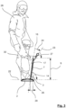
- Such a design also results in the exemplary design of the following Figure 3 .
- a projection of the handrail runs next to the sliding board, which means that the child standing on the sliding board has more space available.
- the inclination of the handrail in the manner described has the advantage that the grip areas of the handrail can be gripped particularly easily by a child standing up on the sliding board.
- the position of the child's wrists caused by the inclination of the handrail helps the child to hold on to the handle particularly well and thus achieve a stable position on the sliding board.
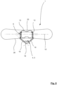
- the handrail can take on the shape of a triangle open at the bottom or a gable roof when viewed from the side of the snowboard.
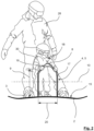
- a corresponding design can also be seen in the embodiment below, where it is particularly well illustrated in Figure 2 visible.
- the advantage of this design of the handrail is again that the grip areas can be gripped particularly comfortably, whereby the child's forearms and hands can be oriented at a slight angle towards each other, comparable to a stable holding position of a steering wheel in a car.
- the handle can be removed from the sliding board without causing any damage, with the handle preferably being screwed to the sliding board.
- the snowboard can be converted particularly easily for different uses.
- a distance measured perpendicular to the upper standing surface of the sliding board, over which the handrail extends above the sliding board is between 40 cm and 100 cm, preferably between 50 cm and 80 cm.
- the measurement described refers to the height of the handle measured from the upper standing surface of the sliding board, whereby the measurements are particularly advantageous for comfortably holding a child. It is preferable that the handrail is at least essentially at chest height of the respective child.
- a distance measured parallel to the longitudinal axis of the sliding board, at which the fastening points of the handle are arranged on the sliding board is between 30 cm and 80 cm, preferably between 40 cm and 70 cm.
- the adult with the shoe bindings is not hindered by the handle when active on the sliding board, while the child riding along can comfortably stand up on the sliding board between the fastening points, i.e. between the posts of the handle, and hold on to the handrail.
- a design of the snowboard can be particularly advantageous in which the sliding board has a plurality of fastening options that are arranged one behind the other when viewed in the longitudinal direction of the sliding board.
- different handles can be connected to the sliding board, in particular screwed, so that in each case a handle adapted to the body size of the respective child can be used and connected to the sliding board.
- the fastening options are, for example and preferably, formed by recesses that penetrate the sliding board in a vertical direction (perpendicular to the upper standing surface of the sliding board) and are therefore suitable for receiving connecting means, in particular screw bolts.
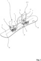
- FIG. 1 An example of implementation that can be found in the Figures 1 to 5 , relates to a snowboard 1 according to the invention, which comprises a sliding board 2, shoe bindings 3 and a handle 4.
- the shoe bindings 3 are intended and designed to accommodate the shoes of an adult person 28 , wherein the shoe bindings 3 provide a force-transmitting connection between the shoes of the person 28 and the sliding board 2.
- the shoe bindings 3 are arranged offset in the longitudinal direction of the sliding board 2 with respect to the handle 4 further in the direction of the opposite ends of the sliding board 2.
- the handle 4 is arranged between the shoe bindings 3 in the longitudinal direction of the sliding board 2. In this way, the handle 4 does not hinder the adult person 28 when using the snowboard 1 as intended.
- the fastening means 25 are screws.
- the points at which the fastening parts 13 of the handle 4 are connected to the sliding board 2 form the fastening points 6, whereby the Handle 4 is connected to the sliding board 2 at a total of two fastening points 6.
- One fastening point 6 is formed on each of the fastening parts 13 .
- the posts 7 of the holding part 5 are oriented parallel to each other in such a way that they extend together within a post plane 16. This is particularly well illustrated by Figure 3 visible.
- the post plane 16 is oriented parallel to the longitudinal axis 10 of the sliding board 2 and also runs slightly laterally in the direction of a side edge 26 of the sliding board 2 with respect to the longitudinal axis 10.
- the post plane 16 is arranged at a slight angle to a vertical so that the post plane 16 , together with a transverse axis 22 of the sliding board 2 or an upper horizontal base surface 15 of the sliding board 2 , encloses an angle 14 that is smaller than 90°. In the example shown, the angle 14 is approximately 80°.
- the handrail 8 is arranged laterally in relation to the sliding board 2 , so that a child 30 standing on the sliding board 2 can comfortably grasp the handrail 8 in front of its upper body when it stands up with its feet on the sliding board 2 .
- a connecting line between the upper ends 17 of the posts 7 runs parallel to the longitudinal axis 10 of the sliding board 2.
- the handrail 8, which bridges the area between the two upper ends 17 of the posts 7 is therefore oriented parallel to the longitudinal axis 10 of the sliding board 2 in the example shown.
- the handrail 8 is also designed to be inclined in the example shown, with a grip plane 23 of the handrail 8, in which grip areas 19 of the handrail 8 extend, being oriented at an angle to the post plane 16.
- the grip plane 23 and the post plane 16 enclose a grip angle 24 , which can be particularly well determined by means of Figure 3
- This grip angle 24 is approximately 30° in the example shown.
- the grip plane 23 is inclined at approximately 50° to a horizontal.
- the fastening parts 13 each extend perpendicular to the longitudinal axis 10 in a transverse direction of the sliding board 2 up to its middle area. This is particularly evident from Figure 5
- the fastening parts 13 thus enable the handle 4 to be fastened in the central region of the sliding board 10, while the posts 7 are arranged offset outwards in the direction of the side edge 26 of the sliding board 2 .
- the handle 4 has an overall S-shape when viewed from the front of the snowboard 1 (corresponds to a side view of the handle 4 ) (see Figure 3 ).
- the handrail 8 has a bent shape in the example shown, with two gripping areas 19 of the handrail 8 being bent against each other to form a bend angle 18.
- the handrail 8 thus takes on the shape of a triangle open at the bottom or a gable roof. This is particularly evident from Figure 2 , which shows the snowboard 1 in a side view (corresponds to a front view of the handle 4 ).
- the inclination of the handle areas 19 in a vertical plane parallel to the longitudinal axis 10 of the sliding board 2 of approximately 45° (see Figure 2 ) offers the advantage that the child 30 can grip the handrail 8 particularly comfortably.
- a stable grip position is made possible so that the child 30 has a secure hold on the sliding board 2.
- the bend angle 18 is approximately 90° in the example shown.
- the handrail 8 is arranged at a vertically measured distance 9 from an upper standing surface 15 of the sliding board 2 , the distance 9 in the example shown being approximately 60 cm.
- the grip areas 19 of the handrail 8 are used as a reference for measuring the distance 9 , which are intended and set up to be grasped by the child.
- the distance 9 describes an effective height of the handrail 8 at which the force is introduced via the child's hands 30 into the holding part 5. takes place.
- the fastening parts 13 or the fastening points 6 are arranged at a distance 20 from each other, which in the example shown is approximately 50 cm. This distance 20 offers sufficient opportunity for the child 30 to position itself between the fastening points 6 of the handle 4 , while the shoe bindings 3 of the adult person 28 are arranged beyond the fastening points 6. This is particularly clear from Figure 2 .
- the snowboard 1 in the example shown is equipped with an anti-slip coating 12 , which is made of an elastomer or an elastomeric material.
- an anti-slip coating 12 which is made of an elastomer or an elastomeric material. This is particularly well suited for the child 30 to be able to stand on it with his shoes, whereby the anti-slip coating 12 has the effect that horizontally oriented forces can be diverted particularly well from the shoes of the child 30 into the sliding board 2 in relation to the upper standing surface 15 of the sliding board 2. This gives the child 30 a secure footing on the sliding board 2.
- auxiliary shoe bindings 11 are conceivable, which are also arranged between the fastening points 6. Such auxiliary shoe bindings 11 are not shown in the example shown.
- the bodies of the adult 28 and the child 30 are positioned in accordance with the Figures 2 and 3 are aligned in the same way, that is, their upper bodies are each oriented in the same direction, namely towards the side edge 26 of the sliding board 2. Accordingly, it is advantageous if the holding part 5 of the handle 4 is offset and inclined towards the side edge 26 of the sliding board 2 , towards which the shoe bindings 3 and optionally the auxiliary shoe bindings 11 are aligned. In other words, the tips of the shoe bindings 3 or the auxiliary shoe bindings 11 point in the direction of the side edge 26, above which the handrail 8 is located.
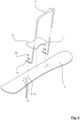
- the handle 4 is designed to be non-destructively dismantled from the sliding board 2. This is particularly evident from Figure 4 This design has the advantage that the handle 4 can be exchanged for another handle 4 particularly easily, so that adaptation to the body size of a particular child 30 is easily possible.
- the sliding board 2 in the example shown is equipped with a plurality of fastening options 21 , which are designed here in the form of recesses 21 made in the sliding board 2 , which penetrate the sliding board 2 in the vertical direction (perpendicular to the standing surface 15 ).
- the Figures 4 and 5 show different possibilities how fastening options 21 can be designed on the sliding board 2 .
Landscapes
- Cleaning Of Streets, Tracks, Or Beaches (AREA)
Applications Claiming Priority (1)
| Application Number | Priority Date | Filing Date | Title |
|---|---|---|---|
| DE102023117225.5A DE102023117225A1 (de) | 2023-06-29 | 2023-06-29 | Snowboard |
Publications (1)
| Publication Number | Publication Date |
|---|---|
| EP4483976A1 true EP4483976A1 (fr) | 2025-01-01 |
Family
ID=91670185
Family Applications (1)
| Application Number | Title | Priority Date | Filing Date |
|---|---|---|---|
| EP24184179.0A Withdrawn EP4483976A1 (fr) | 2023-06-29 | 2024-06-25 | Planche de glisse |
Country Status (2)
| Country | Link |
|---|---|
| EP (1) | EP4483976A1 (fr) |
| DE (1) | DE102023117225A1 (fr) |
Citations (5)
| Publication number | Priority date | Publication date | Assignee | Title |
|---|---|---|---|---|
| FR2732609A1 (fr) * | 1995-04-06 | 1996-10-11 | Lantz Claude | Surf des neiges avec poignee de commande |
| US20030209901A1 (en) * | 2002-05-07 | 2003-11-13 | Hamel Floyd L. | Snow arc ski board and sports arc |
| US20130292922A1 (en) | 2012-04-11 | 2013-11-07 | Kaj Gyr | Lever action snowboard |
| WO2018040993A1 (fr) * | 2016-08-30 | 2018-03-08 | 阎东 | Appareil de ski coopératif multi-personne de type à double planche |
| CN105498189B (zh) * | 2016-02-02 | 2019-03-15 | 阎东 | 动平衡多人协同单板滑行设备 |
Family Cites Families (3)
| Publication number | Priority date | Publication date | Assignee | Title |
|---|---|---|---|---|
| US630697A (en) | 1899-05-16 | 1899-08-08 | John Somerville Highfield | Electrical conducting-main. |
| DE19847675A1 (de) * | 1998-10-15 | 2000-04-20 | Gml Ohg | Snowboard |
| USD630697S1 (en) * | 2010-07-08 | 2011-01-11 | Greenfield Gregory L | Snowboard with adjustable removable handle |
-
2023
- 2023-06-29 DE DE102023117225.5A patent/DE102023117225A1/de active Pending
-
2024
- 2024-06-25 EP EP24184179.0A patent/EP4483976A1/fr not_active Withdrawn
Patent Citations (5)
| Publication number | Priority date | Publication date | Assignee | Title |
|---|---|---|---|---|
| FR2732609A1 (fr) * | 1995-04-06 | 1996-10-11 | Lantz Claude | Surf des neiges avec poignee de commande |
| US20030209901A1 (en) * | 2002-05-07 | 2003-11-13 | Hamel Floyd L. | Snow arc ski board and sports arc |
| US20130292922A1 (en) | 2012-04-11 | 2013-11-07 | Kaj Gyr | Lever action snowboard |
| CN105498189B (zh) * | 2016-02-02 | 2019-03-15 | 阎东 | 动平衡多人协同单板滑行设备 |
| WO2018040993A1 (fr) * | 2016-08-30 | 2018-03-08 | 阎东 | Appareil de ski coopératif multi-personne de type à double planche |
Also Published As
| Publication number | Publication date |
|---|---|
| DE102023117225A1 (de) | 2025-01-02 |
Similar Documents
| Publication | Publication Date | Title |
|---|---|---|
| DE3873113T2 (de) | Brett. | |
| DE2610041A1 (de) | Skibindung | |
| DE2936368A1 (de) | Schneegleiter | |
| DE69305844T2 (de) | Snowboard | |
| DE69827050T2 (de) | Gleitbrett | |
| DE2130198B2 (de) | Bügeiförmiger Skiabweiskörper | |
| EP4483976A1 (fr) | Planche de glisse | |
| DE7002318U (de) | Schneegleitgeraet | |
| DE4411736C1 (de) | Balanceübungsgerät | |
| DE9209879U1 (de) | Mehrzweckwintersportgerät: Ski - Schneeschaufel - Bindungsgrundplatten - Tourenskistöcke - Kombination zu einem Snowboard | |
| DE19705060A1 (de) | Wintersportgerät | |
| DE102012214930B4 (de) | Fahrzeug | |
| DE3811096C2 (fr) | ||
| WO2009138351A2 (fr) | Système de rail et planche de glisse associée | |
| WO1989007475A2 (fr) | Fixation de ski | |
| DE3910468A1 (de) | Schneegleiter | |
| DE3744613C2 (fr) | ||
| EP4153333B1 (fr) | Dispositif de sport d'hiver, notamment un skitrike, permettant de glisser en descente sur trois skis | |
| EP1867367A1 (fr) | Planche de glisse ou de roulage | |
| WO2014009170A1 (fr) | Unité de liaison | |
| WO1993007938A1 (fr) | Systeme de fixation pour dispositifs de patinage a une ou plusieurs rangees de roulettes ou de lames | |
| CH583046A5 (en) | Snow vehicle with ski-like slide plate - front end carries pivoted hinged upright control rod with handle | |
| EP3558476B1 (fr) | Chaussure de saut | |
| DE29622809U1 (de) | Sport-, Freizeit- und/oder Fitneßgerät | |
| DE19531677A1 (de) | Snowboardbindung |
Legal Events
| Date | Code | Title | Description |
|---|---|---|---|
| PUAI | Public reference made under article 153(3) epc to a published international application that has entered the european phase |
Free format text: ORIGINAL CODE: 0009012 |
|
| STAA | Information on the status of an ep patent application or granted ep patent |
Free format text: STATUS: THE APPLICATION HAS BEEN PUBLISHED |
|
| AK | Designated contracting states |
Kind code of ref document: A1 Designated state(s): AL AT BE BG CH CY CZ DE DK EE ES FI FR GB GR HR HU IE IS IT LI LT LU LV MC ME MK MT NL NO PL PT RO RS SE SI SK SM TR |
|
| STAA | Information on the status of an ep patent application or granted ep patent |
Free format text: STATUS: THE APPLICATION IS DEEMED TO BE WITHDRAWN |
|
| 18D | Application deemed to be withdrawn |
Effective date: 20250702 |