EP4484065A1 - Dispositif de traction et de compression portatif et amplificateur de force hydraulique - Google Patents
Dispositif de traction et de compression portatif et amplificateur de force hydraulique Download PDFInfo
- Publication number
- EP4484065A1 EP4484065A1 EP24181435.9A EP24181435A EP4484065A1 EP 4484065 A1 EP4484065 A1 EP 4484065A1 EP 24181435 A EP24181435 A EP 24181435A EP 4484065 A1 EP4484065 A1 EP 4484065A1
- Authority
- EP
- European Patent Office
- Prior art keywords
- hydraulic
- power amplifier
- piston
- pulling
- hydraulic power
- Prior art date
- Legal status (The legal status is an assumption and is not a legal conclusion. Google has not performed a legal analysis and makes no representation as to the accuracy of the status listed.)
- Pending
Links
Images

Classifications
-
- B—PERFORMING OPERATIONS; TRANSPORTING
- B25—HAND TOOLS; PORTABLE POWER-DRIVEN TOOLS; MANIPULATORS
- B25B—TOOLS OR BENCH DEVICES NOT OTHERWISE PROVIDED FOR, FOR FASTENING, CONNECTING, DISENGAGING, OR HOLDING
- B25B29/00—Accessories
-
- F—MECHANICAL ENGINEERING; LIGHTING; HEATING; WEAPONS; BLASTING
- F15—FLUID-PRESSURE ACTUATORS; HYDRAULICS OR PNEUMATICS IN GENERAL
- F15B—SYSTEMS ACTING BY MEANS OF FLUIDS IN GENERAL; FLUID-PRESSURE ACTUATORS, e.g. SERVOMOTORS; DETAILS OF FLUID-PRESSURE SYSTEMS, NOT OTHERWISE PROVIDED FOR
- F15B3/00—Intensifiers or fluid-pressure converters, e.g. pressure exchangers; Conveying pressure from one fluid system to another, without contact between the fluids
-
- F—MECHANICAL ENGINEERING; LIGHTING; HEATING; WEAPONS; BLASTING
- F15—FLUID-PRESSURE ACTUATORS; HYDRAULICS OR PNEUMATICS IN GENERAL
- F15B—SYSTEMS ACTING BY MEANS OF FLUIDS IN GENERAL; FLUID-PRESSURE ACTUATORS, e.g. SERVOMOTORS; DETAILS OF FLUID-PRESSURE SYSTEMS, NOT OTHERWISE PROVIDED FOR
- F15B15/00—Fluid-actuated devices for displacing a member from one position to another; Gearing associated therewith
- F15B15/08—Characterised by the construction of the motor unit
- F15B15/14—Characterised by the construction of the motor unit of the straight-cylinder type
- F15B15/1423—Component parts; Constructional details
- F15B15/1447—Pistons; Piston to piston rod assemblies
-
- B—PERFORMING OPERATIONS; TRANSPORTING
- B21—MECHANICAL METAL-WORKING WITHOUT ESSENTIALLY REMOVING MATERIAL; PUNCHING METAL
- B21J—FORGING; HAMMERING; PRESSING METAL; RIVETING; FORGE FURNACES
- B21J15/00—Riveting
- B21J15/10—Riveting machines
- B21J15/105—Portable riveters
-
- B—PERFORMING OPERATIONS; TRANSPORTING
- B21—MECHANICAL METAL-WORKING WITHOUT ESSENTIALLY REMOVING MATERIAL; PUNCHING METAL
- B21J—FORGING; HAMMERING; PRESSING METAL; RIVETING; FORGE FURNACES
- B21J15/00—Riveting
- B21J15/10—Riveting machines
- B21J15/16—Drives for riveting machines; Transmission means therefor
- B21J15/20—Drives for riveting machines; Transmission means therefor operated by hydraulic or liquid pressure
-
- B—PERFORMING OPERATIONS; TRANSPORTING
- B21—MECHANICAL METAL-WORKING WITHOUT ESSENTIALLY REMOVING MATERIAL; PUNCHING METAL
- B21J—FORGING; HAMMERING; PRESSING METAL; RIVETING; FORGE FURNACES
- B21J15/00—Riveting
- B21J15/10—Riveting machines
- B21J15/16—Drives for riveting machines; Transmission means therefor
- B21J15/26—Drives for riveting machines; Transmission means therefor operated by rotary drive, e.g. by electric motor
-
- B—PERFORMING OPERATIONS; TRANSPORTING
- B25—HAND TOOLS; PORTABLE POWER-DRIVEN TOOLS; MANIPULATORS
- B25B—TOOLS OR BENCH DEVICES NOT OTHERWISE PROVIDED FOR, FOR FASTENING, CONNECTING, DISENGAGING, OR HOLDING
- B25B27/00—Hand tools, specially adapted for fitting together or separating parts or objects whether or not involving some deformation, not otherwise provided for
- B25B27/0007—Tools for fixing internally screw-threaded tubular fasteners
- B25B27/0014—Tools for fixing internally screw-threaded tubular fasteners motor-driven
-
- B—PERFORMING OPERATIONS; TRANSPORTING
- B25—HAND TOOLS; PORTABLE POWER-DRIVEN TOOLS; MANIPULATORS
- B25F—COMBINATION OR MULTI-PURPOSE TOOLS NOT OTHERWISE PROVIDED FOR; DETAILS OR COMPONENTS OF PORTABLE POWER-DRIVEN TOOLS NOT PARTICULARLY RELATED TO THE OPERATIONS PERFORMED AND NOT OTHERWISE PROVIDED FOR
- B25F5/00—Details or components of portable power-driven tools not particularly related to the operations performed and not otherwise provided for
- B25F5/005—Hydraulic driving means
-
- F—MECHANICAL ENGINEERING; LIGHTING; HEATING; WEAPONS; BLASTING
- F15—FLUID-PRESSURE ACTUATORS; HYDRAULICS OR PNEUMATICS IN GENERAL
- F15B—SYSTEMS ACTING BY MEANS OF FLUIDS IN GENERAL; FLUID-PRESSURE ACTUATORS, e.g. SERVOMOTORS; DETAILS OF FLUID-PRESSURE SYSTEMS, NOT OTHERWISE PROVIDED FOR
- F15B15/00—Fluid-actuated devices for displacing a member from one position to another; Gearing associated therewith
- F15B15/08—Characterised by the construction of the motor unit
- F15B15/14—Characterised by the construction of the motor unit of the straight-cylinder type
- F15B15/1423—Component parts; Constructional details
-
- B—PERFORMING OPERATIONS; TRANSPORTING
- B25—HAND TOOLS; PORTABLE POWER-DRIVEN TOOLS; MANIPULATORS
- B25B—TOOLS OR BENCH DEVICES NOT OTHERWISE PROVIDED FOR, FOR FASTENING, CONNECTING, DISENGAGING, OR HOLDING
- B25B27/00—Hand tools, specially adapted for fitting together or separating parts or objects whether or not involving some deformation, not otherwise provided for
- B25B27/02—Hand tools, specially adapted for fitting together or separating parts or objects whether or not involving some deformation, not otherwise provided for for connecting objects by press fit or detaching same
- B25B27/10—Hand tools, specially adapted for fitting together or separating parts or objects whether or not involving some deformation, not otherwise provided for for connecting objects by press fit or detaching same inserting fittings into hoses
Definitions
- the invention relates to a hand-held pulling and pushing device and a hydraulic power amplifier for a hand-held pulling and pushing device for driving pulling and pressing tools.
- Hand-held pulling and pushing devices i.e. devices that can be used by a person in a mobile manner, such as hand-held, electric riveting and pressing devices for setting blind rivet elements, such as blind rivets and blind rivet nuts, or for carrying out punching processes and for setting punch rivets, which have a drive unit with an electric motor-driven threaded spindle of a screw drive, are known in a variety of designs from the prior art.
- the screw drive converts a rotary movement of the electric motor into a linear movement of the pulling or pressing tool in a known manner.
- a pulling mandrel of the blind rivet element is moved axially.
- the hand-held pulling and pushing devices described above are used, for example, in motor vehicle workshops when carrying out repair work on the bodywork of vehicles and when maintaining pipe or cable connections. Depending on the work to be carried out, it is necessary to use the pulling and pushing devices to drive a large number of different interchangeable tools, for example with different levels of force.
- the object of the invention is to provide a hydraulic power amplifier for an electro-mechanically driven, hand-held pulling and pushing device as well as a hand-held pulling and pushing device that can be easily and flexibly adapted to different work processes.
- the invention solves the problem by a hydraulic power amplifier with the features of claim 1 and by a hand-held pulling and pushing device with the features of claim 11.
- Advantageous further developments of hydraulic power amplifiers are specified in claims 2 to 10.
- the hydraulic power amplifier according to the invention (hereinafter referred to as power amplifier) has a housing body with at least one first working chamber filled with hydraulic fluid, for example hydraulic oil, with a connecting section for releasably securing the power amplifier to a connection section of the pulling and pushing device.
- the power amplifier has a first hydraulic piston arranged displaceably in the first working chamber between a starting position and an end position, with a first piston surface and a coupling section for connection to a drive element of the pulling and pushing device that is adjustable relative to the connection section.
- the power amplifier has a second hydraulic piston arranged displaceably in the working chamber at a distance from the first hydraulic piston, with a second piston surface that is larger than the first piston surface, and a mechanical tool connection for pulling and pushing tools.
- a hydraulic power amplifier is a unit designed to increase the tensile and compressive forces generated by the hand-held pulling and pushing device and to transfer them to a pulling or pushing tool.
- the working space is defined by an inner wall of the housing body as well as by the first piston surface of the first hydraulic piston and preferably the first piston surface facing second piston surface of the second hydraulic piston.
- the design of the housing body with a connecting section makes it possible to fix the power amplifier in a fixed position on an electro-mechanically driven pulling and pushing device so that it can be used for operations with higher pulling or pushing forces.
- the first hydraulic piston is reliably connected via its coupling section to a drive element that can be adjusted via the electro-mechanical drive, e.g. a tool holder of the pulling and pushing device.
- the fixed arrangement of the force amplifier on the tension and compression device and the connection of the drive element of the tension and compression device to the first hydraulic piston make it possible to reliably adjust the first hydraulic piston between its starting position and its end position, so that the second hydraulic piston is adjusted accordingly via the pressure generated in the working space.
- the second hydraulic piston is preferably adjustable between a starting position assigned to the starting position and an end position assigned to an end position.
- the second hydraulic piston can be mechanically connected to a pulling and pushing tool via the tool connection, for example via a positive connection in the longitudinal axis direction of the housing body, so that the increased pulling and pushing forces are transmitted to the pulling and pushing tool.
- a change between the use of pulling and pushing forces generated by the pulling and pushing device and the pulling and pushing forces increased by the force amplifier can be carried out easily by disassembling and assembling the force amplifier.
- the pressure of the hydraulic fluid is sufficient to transfer the tensile forces from the first hydraulic piston to the second hydraulic piston.
- the second hydraulic piston is connected to the first hydraulic piston in a form-fitting manner via a connecting element.
- the connecting element is, for example, detachably connected to the second Hydraulic piston or formed in one piece with the second hydraulic piston.
- the connecting element is designed such that a positive connection is created between the first and the second hydraulic piston in the longitudinal axis direction of the housing body.
- the second hydraulic piston is connected to the first hydraulic piston via the connecting element in such a way that the positive connection is created when the first hydraulic piston is adjusted from the end position towards the starting position.
- Such a positive connection ensures that the second hydraulic piston can be easily adjusted by the first hydraulic piston both towards the end position and towards the starting position.
- the positive connection can be designed for this purpose, for example, in the form of a thread or bayonet lock, so that both tensile and compressive forces of the drive element can be transferred from the first hydraulic piston to the second hydraulic piston.
- the first hydraulic piston particularly preferably has a receptacle for arranging the connecting element.
- the receptacle is preferably understood to be a cavity of the first hydraulic piston.
- the receptacle preferably extends with a, for example, circular cross-section in the longitudinal direction of the hydraulic piston.
- the cross-section of the receptacle is preferably adapted to the shape of the connecting element in such a way that the connecting element can be adjusted within the receptacle when the hydraulic pistons are adjusted.
- the receptacle is preferably sealed against the ingress of hydraulic fluid. The receptacle advantageously counteracts unwanted mutual blocking of the hydraulic pistons when the hydraulic pistons move at different speeds.
- a connection between the first hydraulic piston and the drive element of the pulling and pushing device is essential for the function of the power amplifier.
- a coupling element can be provided on the first hydraulic piston, for example, which can be connected to a drive element within the pulling or pushing device.
- the coupling section is designed for connection to a drive element of the pulling and pushing device designed as a tool holder.
- the tool holder is usually a component that is arranged in sections on the front of the pulling and pushing device and is connected to the electro-mechanical drive, for example via a screw drive, which enables the pulling and pressing tools to be changed easily.
- the good accessibility required for this makes it particularly easy to connect the first hydraulic piston of the power amplifier to the tool holder, for example to bring it into contact with it. It is also possible to connect them in such a form-fitting manner that the first hydraulic piston is positively connected to the tool holder in both adjustment directions of the hydraulic pistons.
- connection of the power amplifier to the tension and pressure device can basically be designed in any way.
- the connecting section of the power amplifier has a thread or locking body for releasable attachment to the connection section of the tension and pressure device, which has a thread or locking body receptacles.
- a corresponding design of the connecting section enables a secure and easily detachable connection of the power amplifier to the tension and pressure device, without the need for additional components and/or securing elements. To remove the connection between the power amplifier and the tension and pressure device, it is only necessary to unscrew it from the thread or to remove the locking connection.
- the hydraulic pistons are arranged relative to one another, for example, in such a way that the hydraulic pistons can be adjusted along an axis, for example in the direction of the longitudinal axis of the housing body. According to an advantageous development of the invention, however, it is provided that the hydraulic pistons can be arranged at an angle to one another.
- the hydraulic pistons are arranged relative to one another, for example, at an angle, for example between 70° - 180°, preferably 75 -180°, particularly preferably 80 -180°.
- the angle between the hydraulic pistons preferably describes the angle between a longitudinal axis of the first hydraulic piston and a longitudinal axis of the second hydraulic piston.
- the housing body is particularly preferably designed in such a way that the hydraulic pistons in the protruding area can be adjusted between different Angular positions, for example 90°, 135° and 180°.
- the housing body is preferably designed at least in two parts.
- the housing body preferably has two housing parts that can be adjusted to rotate relative to one another by a joint element.
- the joint element is preferably arranged on the housing body in the area of the working space filled with hydraulic fluid, particularly preferably between the hydraulic pistons.
- the advantageous design of the housing body enables a simple and, if necessary, flexible change in the direction of force due to the flexible or fixed arrangement of the hydraulic pistons at an angle to one another, so that the pulling and pushing device connected to the hydraulic power amplifier can be used particularly easily in different, even narrow, environments, such as hard-to-reach areas of a motor vehicle.
- the housing body has a second working chamber filled with hydraulic fluid, wherein the second working chamber is formed by two partial working chambers connected by means of a hydraulic coupling.
- the partial working chambers are preferably separated from one another, preferably in the longitudinal axis direction of the housing body, by the hydraulic pistons and/or the first working chamber, and are connected to one another via the hydraulic coupling, for example a line for the hydraulic fluid.
- the first hydraulic piston has a third piston surface arranged at a distance from the first piston surface and the second hydraulic piston has a fourth piston surface arranged at a distance from the second piston surface, wherein the third and fourth piston surfaces are each arranged in one of the partial working spaces of the second working space.
- the partial working spaces are delimited by the two hydraulic pistons, in particular the third piston surface or the fourth piston surface, and the inner wall of the housing body.
- the third piston surface is preferably arranged on the first hydraulic piston facing away from the first piston surface.
- the fourth piston surface is arranged on the second hydraulic piston facing away from the second piston surface.
- the piston surfaces of the two hydraulic pistons are each spaced apart by a distance, particularly preferably the distance between the piston surfaces of a hydraulic piston defining support element.
- the second working chamber and the advantageous design of the hydraulic pistons enable a simple and reliable hydraulic reset of the second hydraulic piston when the first hydraulic piston is adjusted from the end position to the starting position.
- this design of the invention can counteract the risk of cavitation of hydraulic fluid in the first working chamber.
- the second working chamber is connected to a compensation volume for thermal compensation of the hydraulic fluid.
- the compensation volume is preferably understood to be a container connected to the second working chamber, for example via a line.
- the compensation volume is preferably designed to absorb part of the hydraulic fluid in the second working chamber when it expands due to heat and, particularly preferably, to release it back to the second working chamber.
- the compensation volume has a third hydraulic piston.
- the third hydraulic piston is preferably adjustable for receiving and/or releasing the hydraulic fluid within the compensation volume.
- the compensation volume preferably has a spring element for preloading, in particular spring preloading, the third hydraulic piston in order to automatically release the hydraulic fluid received in the compensation volume to the second working chamber.
- the tool connection has a quick coupling.
- the quick coupling describes a mechanical coupling of the tool connection, which is preferably designed in such a way that pulling and pushing tools can be connected to the tool holder easily and quickly.
- the quick coupling is designed in the form of a bayonet lock or as a ball lock. The quick coupling enables the pulling and pushing tools that can be connected to the power amplifier to be changed in a simple and convenient manner.
- the hand-held pulling and pushing device not only enables mechanically driven pulling and pressing tools to be driven with the maximum force generated by the pulling and pushing device via the power amplifier, but also with forces exceeding this maximum force, whereby, if necessary, it is possible to switch between an original drive by the pulling and pushing device and the increased drive via the power amplifier in a simple manner by connecting or disconnecting the power amplifier to the pulling and pushing device.
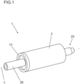
- Figure 1 shows in a sectional view an embodiment of a hydraulic power amplifier 1 with a housing body 2 and a cover 13 sealingly closing the housing body 2.
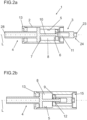
- FIG. 2a Within the housing body 2 are a Figure 2a presented initial situation and one in Figure 2b
- An inner wall 5 of the housing body 2 together with a first piston surface 6 of the first hydraulic piston 3 and a second piston surface 7 of the second hydraulic piston 4 arranged at a distance from the first piston surface 6 and facing it, defines a first working chamber 8 which is filled with hydraulic fluid.
- the second hydraulic piston 4 is arranged within the housing body 2 between a Fig. 2a shown starting position and one assigned to the end position, in Fig. 2b The end position shown can be adjusted.
- the first hydraulic piston 3 is in the Figure 2b
- the starting position shown is provided by a connecting element 10 which positively connects the hydraulic pistons 3, 4 and which is arranged at one end on the second hydraulic piston 4 and at the other end is accommodated in a receptacle in the form of a cavity 11 arranged on the first hydraulic piston 3.
- the connecting element 10 rests on an inner surface 12 of the cavity 11, so that when the first hydraulic piston 3 is returned from the end position to the starting position, a positive connection of the hydraulic pistons 3, 4 is formed in the direction of a longitudinal axis L of the housing body.
- the second hydraulic piston 4 can be mechanically connected to a pull and push tool (not shown) via a tool connection 28, so that the pull and push forces increased by the power amplifier 1 are transmitted to the pull and push tool.
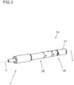
- the housing body 2 has a connecting portion 15 which is designed for detachable connection to a connection portion 16 of the tension and compression device 14, so that the force amplifier 1 can be arranged in a fixed position on the tension and compression device 14.
- the pull and push device 14 has a drive unit 18 with an electric motor 17, by means of which a threaded spindle 19 of a screw drive 20 arranged in a housing body 27 can be driven.
- the screw drive 20 also has a threaded nut 21 arranged on the threaded spindle 19, which is mounted on the housing body 27 in a rotationally fixed manner.
- the threaded nut 21 serves to drive a tool holder designed as a piston rod 22, which is adjustably mounted in the longitudinal axis direction of the threaded spindle 19, so that the first hydraulic piston 3 can be adjusted in the direction of the power amplifier 1 by means of the pull and push device 14 via the piston rod 22 as a drive element.
- the first hydraulic piston 3 has a coupling section 24 on an end face 23 facing the piston rod 22, so that movements of the piston rod 22 are reliably transmitted to the first hydraulic piston 6.
- the piston rod 22 is connected to the threaded nut 21 via a detachable connected coupling unit 25, which rests at its end opposite the piston rod 22 on an end face 26 of the threaded nut 21 facing away from the piston rod 22.
- a bearing unit 38 which is attached to the coupling unit 25, serves to mount the threaded nut 21 on the housing body 27 in a rotationally secure manner.
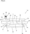
- the hydraulic booster 1a shown which represents a further embodiment of the hydraulic booster 1, the same reference numerals are used for the same components.
- the hydraulic booster 1a differs from the booster according to Fig. 1 to 4b due to the missing connecting element 15, a second working chamber 29 and an alternative design of the hydraulic pistons 3a, 4a.
- the first hydraulic piston 3a has a third piston surface 30 arranged at a distance from the first piston surface 6 and the second hydraulic piston 7 has a fourth piston surface 31 arranged at a distance from the second piston surface 7.
- the second working chamber 29 is formed by two partial working chambers 32, which are each delimited by the third piston surface 30 or the fourth piston surface 31, and the inner wall 5 of the housing body 2a.
- the partial working chambers 32 are separated from one another in the longitudinal axis direction of the housing body 2a by the hydraulic pistons 3a, 4a and the first working chamber 8 and are connected to one another via a hydraulic coupling in the form of a line 33 for the hydraulic fluid.
- the piston surfaces 6, 7, 30, 31 of the two hydraulic pistons 3a, 4a are each connected to one another via a support element 34 which defines the distance between the piston surfaces 6, 7, 30, 3 of a hydraulic piston 3a, 4a.
- the second working chamber 29 is also connected to a compensation volume 35 for thermal compensation of the hydraulic fluid.
- the compensation volume 35 has a spring element 36 for spring preloading a third hydraulic piston 37 arranged on the compensation volume 35.
- the hydraulic power amplifier 1 enables pulling and pushing tools to be driven with increased pressing force in a simple and reliable manner by means of the hand-held pulling and pushing device 14, whereby the pulling and pushing device 14 can be used flexibly for various work processes.
Landscapes
- Engineering & Computer Science (AREA)
- Mechanical Engineering (AREA)
- Physics & Mathematics (AREA)
- Fluid Mechanics (AREA)
- General Engineering & Computer Science (AREA)
- Supply Devices, Intensifiers, Converters, And Telemotors (AREA)
- Actuator (AREA)
- Press Drives And Press Lines (AREA)
Priority Applications (1)
| Application Number | Priority Date | Filing Date | Title |
|---|---|---|---|
| EP25155010.9A EP4534250A3 (fr) | 2023-06-26 | 2024-06-11 | Dispositif de traction et de compression portatif et amplificateur de force hydraulique |
Applications Claiming Priority (1)
| Application Number | Priority Date | Filing Date | Title |
|---|---|---|---|
| DE102023116739.1A DE102023116739A1 (de) | 2023-06-26 | 2023-06-26 | Handhaltbare Zug- und Druckvorrichtung sowie hydraulischer Kraftverstärker |
Related Child Applications (1)
| Application Number | Title | Priority Date | Filing Date |
|---|---|---|---|
| EP25155010.9A Division EP4534250A3 (fr) | 2023-06-26 | 2024-06-11 | Dispositif de traction et de compression portatif et amplificateur de force hydraulique |
Publications (1)
| Publication Number | Publication Date |
|---|---|
| EP4484065A1 true EP4484065A1 (fr) | 2025-01-01 |
Family
ID=91481871
Family Applications (2)
| Application Number | Title | Priority Date | Filing Date |
|---|---|---|---|
| EP25155010.9A Pending EP4534250A3 (fr) | 2023-06-26 | 2024-06-11 | Dispositif de traction et de compression portatif et amplificateur de force hydraulique |
| EP24181435.9A Pending EP4484065A1 (fr) | 2023-06-26 | 2024-06-11 | Dispositif de traction et de compression portatif et amplificateur de force hydraulique |
Family Applications Before (1)
| Application Number | Title | Priority Date | Filing Date |
|---|---|---|---|
| EP25155010.9A Pending EP4534250A3 (fr) | 2023-06-26 | 2024-06-11 | Dispositif de traction et de compression portatif et amplificateur de force hydraulique |
Country Status (4)
| Country | Link |
|---|---|
| US (1) | US20240426322A1 (fr) |
| EP (2) | EP4534250A3 (fr) |
| CN (1) | CN119196113A (fr) |
| DE (1) | DE102023116739A1 (fr) |
Families Citing this family (1)
| Publication number | Priority date | Publication date | Assignee | Title |
|---|---|---|---|---|
| DE102021131294A1 (de) * | 2021-11-29 | 2023-06-01 | Tkr Spezialwerkzeuge Gmbh | Handhaltbare Zug- und Druckvorrichtung |
Citations (2)
| Publication number | Priority date | Publication date | Assignee | Title |
|---|---|---|---|---|
| WO2006057962A1 (fr) * | 2004-11-24 | 2006-06-01 | Emerson Electric Co. | Appareil pour pressage en plusieurs etapes servant a realiser un raccordement de tuyaux emmanche a la presse |
| DE202018106240U1 (de) * | 2018-11-01 | 2020-02-04 | WS Wieländer + Schill Professionelle Karosserie-Spezialwerkzeuge GmbH & Co. KG | Zug- und/oder Pressvorrichtung |
Family Cites Families (2)
| Publication number | Priority date | Publication date | Assignee | Title |
|---|---|---|---|---|
| DE20103209U1 (de) * | 2001-02-23 | 2001-06-13 | Britax-Teutonia Kinderwagenfabrik GmbH, 32120 Hiddenhausen | Nietwerkzeug |
| DE102021131294A1 (de) * | 2021-11-29 | 2023-06-01 | Tkr Spezialwerkzeuge Gmbh | Handhaltbare Zug- und Druckvorrichtung |
-
2023
- 2023-06-26 DE DE102023116739.1A patent/DE102023116739A1/de active Pending
-
2024
- 2024-06-11 EP EP25155010.9A patent/EP4534250A3/fr active Pending
- 2024-06-11 EP EP24181435.9A patent/EP4484065A1/fr active Pending
- 2024-06-24 US US18/752,751 patent/US20240426322A1/en active Pending
- 2024-06-25 CN CN202410826560.6A patent/CN119196113A/zh active Pending
Patent Citations (2)
| Publication number | Priority date | Publication date | Assignee | Title |
|---|---|---|---|---|
| WO2006057962A1 (fr) * | 2004-11-24 | 2006-06-01 | Emerson Electric Co. | Appareil pour pressage en plusieurs etapes servant a realiser un raccordement de tuyaux emmanche a la presse |
| DE202018106240U1 (de) * | 2018-11-01 | 2020-02-04 | WS Wieländer + Schill Professionelle Karosserie-Spezialwerkzeuge GmbH & Co. KG | Zug- und/oder Pressvorrichtung |
Also Published As
| Publication number | Publication date |
|---|---|
| EP4534250A2 (fr) | 2025-04-09 |
| CN119196113A (zh) | 2024-12-27 |
| EP4534250A3 (fr) | 2025-07-02 |
| DE102023116739A1 (de) | 2025-01-02 |
| US20240426322A1 (en) | 2024-12-26 |
Similar Documents
| Publication | Publication Date | Title |
|---|---|---|
| DE102009054930B4 (de) | Bohrmaschine | |
| DE102009054923B4 (de) | Handwerkzeugmaschine | |
| WO2019053155A1 (fr) | Procédé et système de changement automatique d'arbres | |
| EP3837150A1 (fr) | Colonne de direction pour véhicule automobile | |
| EP2218549A1 (fr) | Dispositif doté d'un levier pouvant être entraîné dans des directions opposées par un entraînement à l'aide d'un actionneur et d'un agencement articulé de levier à genouillère | |
| EP4484065A1 (fr) | Dispositif de traction et de compression portatif et amplificateur de force hydraulique | |
| DE102023116744B3 (de) | Handhaltbare Zug- und Druckvorrichtung sowie modulares System | |
| EP3025824B1 (fr) | Outil hydraulique mobil | |
| EP4484061B1 (fr) | Dispositif de traction et d'impression portatif | |
| DE102023116741B3 (de) | Handhaltbare Zug- und Druckvorrichtung sowie mechanischer Kraftverstärker | |
| EP3153280B1 (fr) | Outil avec interface universelle pour interface d'entraînement | |
| DE202012100803U1 (de) | Einrichtung zur Zahnspiel-Einstellung sowie Linearantrieb | |
| DE102007023807B4 (de) | Umschaltmittel für Schrauber mit zwei Abtrieben | |
| EP1169152B1 (fr) | Dispositif pour l'usinage de tiges a bague de serrage | |
| EP4484063B1 (fr) | Dispositif de traction et de pression portatif et actionneur hydraulique | |
| WO1999008011A1 (fr) | Element de palier pour dispositif de reglage dans des vehicules a moteur | |
| DE102008057424B4 (de) | Vorsatzvorrichtung für eine Rohrpressmaschine | |
| DE102004025061B4 (de) | Werkzeugantrieb, insbesondere zum automatischen Entgraten, Kantenbrechen oder Verputzen von Werkstücken | |
| DE102006015458A1 (de) | Verfahren und Werkzeugeinrichtung zum Umformen | |
| DE102023116745B4 (de) | Umlenkeinheit | |
| DE69510349T2 (de) | Werkzeugkupplung mit zentrier- und spanneinrichtungen | |
| DE102017104666A1 (de) | Wechselwerkzeugsystem | |
| DE10016144A1 (de) | Vorrichtung zum Justieren einer Baugruppe, insbesondere einer Instrumententafel eines Kraftfahrzeuges | |
| DE20203791U1 (de) | Kniehebelspannvorrichtung | |
| DE202023101346U1 (de) | Spann- oder Greifvorrichtung |
Legal Events
| Date | Code | Title | Description |
|---|---|---|---|
| PUAI | Public reference made under article 153(3) epc to a published international application that has entered the european phase |
Free format text: ORIGINAL CODE: 0009012 |
|
| STAA | Information on the status of an ep patent application or granted ep patent |
Free format text: STATUS: THE APPLICATION HAS BEEN PUBLISHED |
|
| AK | Designated contracting states |
Kind code of ref document: A1 Designated state(s): AL AT BE BG CH CY CZ DE DK EE ES FI FR GB GR HR HU IE IS IT LI LT LU LV MC ME MK MT NL NO PL PT RO RS SE SI SK SM TR |
|
| STAA | Information on the status of an ep patent application or granted ep patent |
Free format text: STATUS: REQUEST FOR EXAMINATION WAS MADE |
|
| 17P | Request for examination filed |
Effective date: 20250122 |
|
| STAA | Information on the status of an ep patent application or granted ep patent |
Free format text: STATUS: EXAMINATION IS IN PROGRESS |
|
| 17Q | First examination report despatched |
Effective date: 20260216 |