EP3153280B1 - Outil avec interface universelle pour interface d'entraînement - Google Patents
Outil avec interface universelle pour interface d'entraînement Download PDFInfo
- Publication number
- EP3153280B1 EP3153280B1 EP16187743.6A EP16187743A EP3153280B1 EP 3153280 B1 EP3153280 B1 EP 3153280B1 EP 16187743 A EP16187743 A EP 16187743A EP 3153280 B1 EP3153280 B1 EP 3153280B1
- Authority
- EP
- European Patent Office
- Prior art keywords
- tool
- interface
- output interface
- output
- universal
- Prior art date
- Legal status (The legal status is an assumption and is not a legal conclusion. Google has not performed a legal analysis and makes no representation as to the accuracy of the status listed.)
- Active
Links
Images

Classifications
-
- B—PERFORMING OPERATIONS; TRANSPORTING
- B25—HAND TOOLS; PORTABLE POWER-DRIVEN TOOLS; MANIPULATORS
- B25F—COMBINATION OR MULTI-PURPOSE TOOLS NOT OTHERWISE PROVIDED FOR; DETAILS OR COMPONENTS OF PORTABLE POWER-DRIVEN TOOLS NOT PARTICULARLY RELATED TO THE OPERATIONS PERFORMED AND NOT OTHERWISE PROVIDED FOR
- B25F3/00—Associations of tools for different working operations with one portable power-drive means; Adapters therefor
Definitions
- the present invention relates to a tool with a universal interface for an output interface.
- Tools such as screwing tools, drilling tools, riveting tools, welding tools, punching tools, etc. are used in the production of vehicles such as trucks, motor vehicles, aircraft, etc. With such tools, depending on the task, it is necessary to use different tool elements for treating at least one workpiece, such as at least one sheet metal part for an aircraft wing, etc.
- a tool attachment with a fastening interface on an attachment housing which comprises an angular position setting unit for setting a predetermined angular position and a locking unit.
- the DE 20 2006 010155 U1 discloses a toothed ring connection structure for a power tool with different matching threaded bushings for coupling the toothed ring with different functional end pieces.
- a tool unit for a power tool with a mechanical interface for connecting the tool unit to a base unit is known, the mechanical interface also being used for receiving a drive of the base unit and on the side of a tool facing away from the base unit.
- the DE 10 2004 006205 B3 discloses an attachable drill adapter for use on a screwdriver.
- a tool with a universal interface for an output interface with which the problems mentioned above can be solved.
- a tool with a universal interface for an output interface is to be provided, in which a single interface fulfills the above-mentioned requirements of both the automotive industry and the aircraft industry for various outputs, such as angle heads, straight drives, flat keys or the like.
- the tool has a universal interface suitable for mounting at least two different output interfaces, which are designed to receive a tool element for treating a workpiece, the universal interface being designed such that either an output interface that can be assembled without tools or an output interface that can be assembled with a locking tool can be attached to the universal interface is.
- the design of the output interface also has the advantage of a small variety of tools, which increases the number of pieces of the tool and thereby makes the tool inexpensive to manufacture.
- the advantage lies in a uniform tool, which results in less spare parts and greater flexibility. This also results in cost savings.
- Another advantage of the tool is that the handling of the tool is easy to understand for every user. This results in short learning phases, which increases the acceptance of the tool by the user and reduces the costs for using the tool.
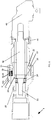
- Fig. 1 shows schematically a tool 1, which can be used for example in a production plant for objects made of workpieces.
- the production system 4 is, for example, a production facility or production line for vehicles, in particular motor vehicles, airplanes, etc., furnishings, electrical appliances, etc.
- the tool 1 has a control 11, a measuring element 12, a gear 13, a motor 14, electronics 15, an energy supply interface 16, a housing 17 and a universal interface 20 with a thread 21 of a locking contour 22 and an output shaft 23 for an output interface, the regarding Fig. 2 and Fig. 4 is explained in more detail.
- the universal interface 20 is therefore provided for receiving the output interface, as in FIG Fig. 2 and Fig. 4 is shown in more detail and described later.
- Fig. 1 is the tool 1 a screwing tool, which is controlled for power supply via the power supply interface 16 with the controller 11 and the electronics 15 for driving the motor 14.
- the energy supply interface 16 can in particular be designed as a battery, which can be designed to be rechargeable or non-rechargeable.
- a rotation of the drive shaft (not shown) resulting from the drive of the motor 14 is converted into a movement of the output shaft 23 with the aid of the gear 13.
- the measuring element 12 physical quantities can be measured that occur during a machining process with the tool 1.
- the tool 1 is therefore also referred to as a measuring screwing tool.
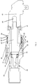
- Fig. 2 shows a sectional view of the universal interface 20, on which an output interface 30 with an angular head 40 is mounted using a union nut 41 in connection with a further output shaft 42.
- the angle head 40 is provided for a tool element with which a workpiece is to be machined.
- the angle head 40 is on that one end of the axis of the output interface 30 is mounted.
- the other end of the axis of the output interface 30 faces the universal interface 20.
- the output interface 30 is designed as a sliding sleeve that has a quick-change function.
- the output interface 30 can be mounted on the universal interface 20 or removed from the universal interface 20 faster than an interface that can be assembled or disassembled with a locking tool, not shown.
- the universal interface 20 and the output interface 30 are configured such that the output interface 30 is pushed in the axial direction of the output shafts 23, 42 over the universal interface 20 or is pushed down by the universal interface 20.
- the output shaft 23 is rotatably mounted with a bearing 24, which is in particular designed as a ball bearing.
- the output shaft 23 is in this case connected to the output shaft 42, which is adapted at a distance from the inside to a locking ring 25 which secures the bearing 24 in the universal interface 20.
- the locking ring 25 can be designed with an external thread, which is screwed into an internal thread 26 of the universal interface 20. However, the locking ring 25 can also be fastened in a different way in the universal interface 20, for example in a press fit, etc.
- the output shaft 42 engages in a recess 43 of the angle head 40 at its end facing the angle head 40.
- the output shaft 42 is arranged in the recess 43 such that the output shaft 42 in the in Fig. 2 shown state in the bearing 24 is rotatably connected to the output shaft 23.
- the output interface 30 has on its annular inside an inner contour 31, which is simply the thread 21 of the Universal interface 20 can be pushed without the inner contour 31 being screwed onto the thread 21 of the universal interface 20.
- the inner contour 31 is therefore preferably at a distance from the thread 21, in particular smooth or as a flat surface.
- the inner contour 31 therefore does not have to be designed as an internal thread, so that no threaded connection is formed between the thread 21 and the inner contour 38.
- a space 32 is provided which can be used for further components, such as sensors or the like.
- At least one locking body 33 in the form of at least one ball is also provided, which is arranged to be radially movable with respect to the output shaft 42.
- the at least one locking body 33 can engage in the locking contour 22 of the universal interface 20 and lock the output shaft 42 and thus also the output shaft 23 on the output interface 30 when an annular projection 34 presses the locking body 33 in the direction of the output shaft 42.
- a snap ring 35 is provided in the area of the end of the output interface 30 which faces the union nut 41.
- the snap ring 35 is used for the axial support of a spring 36, which is axially supported at one end with an annular projection 34 and with its other end abuts a support ring 37 arranged on the output interface 30, which is supported by the snap ring 35.
- the spring 36 acts as a compression spring, the spring preload of which is ensured by the support ring 37 and the snap ring 35.
- the output interface 30 can be kept permanently in its locking position via the spring 36, in which the output shaft 42 is axially locked with the locking body 33. For unlocking, the at least one locking body 33 can move outwards by moving the output interface 30 to the right in the drawing, as in FIG Fig.
- the at least one locking body 33 is in its locking position from the annular projection 34 radially in the direction of the axis of the output shaft 42 pressed to lock the output shaft 42 and thus also the output shaft 23.
- the snap ring 35 has the function of receiving the output shafts 42, 23 in the form of a quick-change chuck.
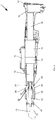
- Fig. 3 the tool 1 is shown, on the universal interface 20 of which the output interface 30 is mounted with the angle head 40.
- the output interface 30 can be used to implement a quick-change device for attaching the output interface 30 without tools to the output, more precisely the universal interface 20 of the tool 1.
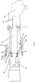
- Fig. 4 shows in relation to a second exemplary embodiment in a sectional view the universal interface 20, on which an output interface 50 with the angle head 40 is mounted using the union nut 41 in connection with the output shafts 23, 42.
- the angle head 40 is mounted on one end of the axis of the output interface 50.
- the other end of the axis of the output interface 50 faces the universal interface 20.
- the output shaft 23 is mounted with the bearing 24 supported on the securing ring 25 and can be connected in a rotationally fixed manner to the output shaft 42, as described in relation to the preceding exemplary embodiment.
- the output interface 50 is designed as a union nut, which has no quick-change function. Instead, the output interface 50 is firmly screwed onto the thread 21 of the universal interface 20 with an internal thread 51. This can also be done with the help of a locking tool, not shown.
- a space 52 of the output interface 50 for components is provided.
- locking devices 53 can engage in the locking contour 22 of the universal interface 20. This will make the Output interface 50 is supported when screwing onto the universal interface 20 and mounted so that the angle head 40 can be driven as a tool element by the output shaft 23 via the output shaft 42.
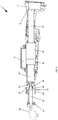
- Fig. 5 the tool 1 is shown, on the universal interface 20 of which the output interface 50 with the angle head 40 is mounted.
- Fig. 6 shows an output interface 500 according to a third embodiment.
- the output interface 500 is constructed essentially in the same way as described in relation to the output interface 50 of the preceding exemplary embodiment.
- the output interface 500 has an identification element 54 which is arranged in the space 52.
- the universal interface 20 or the measuring element 12 ( Fig. 1 ) of the tool in addition to their configurations and functions according to the first exemplary embodiment, equipped with a transmitter / receiver unit 19.
- the transmitter / receiver unit 19 In cooperation with the identification element 54, the transmitter / receiver unit 19 enables the tool 1 to recognize the output interface 30 and to adopt it in the identification of the tool 1.
- the tool 1 can also be designed as a drilling tool, a riveting tool, a welding tool, a punching tool, etc.
- the tool 1, 2 is preferably a hand-held tool, since such a tool is particularly well suited for changing locations.
- a "hand-held tool” in the sense of this application also includes a tool that is guided by a robot or a similar movement device.
- the output interface 30 can also be equipped in the space 32 in the same way as the output interface 500 with an identification element 54.
- the output shafts 23, 42 can also be configured in one piece. In this case, the output shaft 42 would protrude from the universal interface 20 if a tool element, such as the angle head 40, is mounted on the universal interface 20 with one of the output interfaces 30, 50, 500. In order to minimize the risk of injury to a user of the tool 1, the form of embodiment of the output shafts 23, 42 described in the exemplary embodiments is therefore preferred.
- angle head 40 instead of the angle head 40, other drives, such as straight drives, flat keys or the like, can also be mounted on the universal interface 20 with one of the drive interfaces 30, 50, 500.
- the tool 1 can also be designed without a measuring element 12 if no measurements with a measuring element 12 have to be carried out during the machining of the workpiece.
Landscapes
- Engineering & Computer Science (AREA)
- Mechanical Engineering (AREA)
- Details Of Spanners, Wrenches, And Screw Drivers And Accessories (AREA)
- Automatic Assembly (AREA)
Claims (6)
- Outil de vissage mesureur (1) comprenant une interface universelle (20) appropriée pour le montage d'au moins deux interfaces de prise de force différentes (30 ; 50 ; 500) qui sont conçues pour recevoir un élément d'outil pour le traitement d'une pièce, l'interface universelle (20) étant configurée de telle sorte que soit une interface de prise de force (30) pouvant être montée sans outil, soit une interface de prise de force devant être montée avec un outil de fixation (50 ; 500) puisse être fixée à l'interface universelle (20), l'interface universelle (20) présentant un contour d'encliquetage (22) soit qui est approprié pour l'engagement d'un corps de verrouillage (33) d'une interface de prise de force (30) pouvant être montée sans outil, soit qui est approprié pour l'engagement avec au moins un dispositif d'encliquetage (53) de l'interface de prise de force (50 ; 500) devant être montée avec un outil de montage, l'interface universelle (20) présentant un filetage (21) avec un filetage extérieur qui est approprié pour le vissage d'un filetage intérieur (51) de l'interface de prise de force (50 ; 500) devant être montée avec l'outil de fixation.
- Outil (1) selon l'une quelconque des revendications précédentes, dans lequel l'interface universelle (20) présente en outre un palier (24) pour le support sur palier rotatif d'un arbre de prise de force (23) de l'outil (1), et une bague de fixation (25) pour la fixation du palier (24) dans l'interface universelle (20), la bague de fixation (25) étant vissée dans l'interface universelle (20) ou étant disposée avec ajustement serré.
- Outil (1) selon l'une quelconque des revendications précédentes, comprenant en outre un dispositif émetteur/récepteur (19) pour envoyer et/ou recevoir des données d'identification pour l'identification de l'interface de prise de force (30, 50, 500).
- Outil (1) selon l'une quelconque des revendications précédentes, dans lequel l'interface de prise de force (30 ; 50 ; 500) est un écrou de raccordement ou un mandrin de serrage à raccord rapide.
- Interface de prise de force (30) pour un outil (1) selon l'une quelconque des revendications précédentes, l'interface de prise de force (30) présentant un contour intérieur (31) qui peut être déplacé par le biais du filetage (21) de l'interface universelle (20) sans connexion filetée, comprenant en outre un dispositif de verrouillage (33) pour le verrouillage de l'interface de prise de force (3) à un contour d'encliquetage (22) de l'interface universelle (20) et un ressort (36) pour la sollicitation en pression du dispositif de verrouillage (33), présentant également un filetage intérieur (51) qui peut être vissé sur le filetage (21) de l'interface universelle (20) pour créer une connexion filetée, et l'interface de prise de force (50 ; 500) présentant un dispositif d'encliquetage (53) pour l'encliquetage dans le contour d'encliquetage (21) de l'interface universelle (20).
- Interface de prise de force (30 ; 50 ; 500) selon la revendication 5, comprenant en outre un élément d'identification (54) pour envoyer des données d'identification de l'interface de prise de force (30 ; 50 ; 500) à un dispositif émetteur/récepteur (19) de l'outil (1) pour l'identification de l'interface de prise de force (30 ; 50 ; 500) avec l'outil (1).
Applications Claiming Priority (1)
| Application Number | Priority Date | Filing Date | Title |
|---|---|---|---|
| DE102015219570.8A DE102015219570A1 (de) | 2015-10-09 | 2015-10-09 | Werkzeug mit universalschnittstelle für eine abtriebsschnittstelle |
Publications (2)
| Publication Number | Publication Date |
|---|---|
| EP3153280A1 EP3153280A1 (fr) | 2017-04-12 |
| EP3153280B1 true EP3153280B1 (fr) | 2020-02-19 |
Family
ID=57003335
Family Applications (1)
| Application Number | Title | Priority Date | Filing Date |
|---|---|---|---|
| EP16187743.6A Active EP3153280B1 (fr) | 2015-10-09 | 2016-09-08 | Outil avec interface universelle pour interface d'entraînement |
Country Status (3)
| Country | Link |
|---|---|
| EP (1) | EP3153280B1 (fr) |
| CN (1) | CN106944981B (fr) |
| DE (1) | DE102015219570A1 (fr) |
Families Citing this family (3)
| Publication number | Priority date | Publication date | Assignee | Title |
|---|---|---|---|---|
| DE102021203946B3 (de) * | 2021-04-21 | 2022-07-07 | Robert Bosch Gesellschaft mit beschränkter Haftung | Abtriebseinheit für ein Schraubsystem, Schraubsystem und Herstellungsverfahren |
| WO2025117585A1 (fr) | 2023-11-30 | 2025-06-05 | Stanley Black & Decker, Inc. | Outil électrique à têtes multiples et système de fixation associé et systèmes de fixation de têtes sur celui-ci |
| US12594657B2 (en) | 2023-11-30 | 2026-04-07 | Stanley Black & Decker, Inc. | Multi-headed power tool and systems for fastening heads thereon |
Family Cites Families (8)
| Publication number | Priority date | Publication date | Assignee | Title |
|---|---|---|---|---|
| DE10254829A1 (de) * | 2002-11-25 | 2004-06-03 | Robert Bosch Gmbh | Elektrohandwerkzeugmaschine |
| DE102004006205B3 (de) * | 2004-02-09 | 2005-05-19 | Hilti Ag | Bohradapter |
| TWM299627U (en) * | 2006-04-26 | 2006-10-21 | Tranmax Machinery Co Ltd | Improvement structure for gear ring of electric tool |
| US20080214097A1 (en) * | 2007-03-02 | 2008-09-04 | Ting Hui Kao | Handheld electric grinder |
| EP2177322B1 (fr) * | 2008-10-20 | 2014-05-07 | CEKA Elektrowerkzeuge AG + Co. KG | Unité d'outil pour un outil électrique, outil électrique et procédé de fonctionnement d'un outil électrique |
| DE102013213814A1 (de) * | 2012-11-15 | 2014-05-15 | Robert Bosch Gmbh | Werkzeugvorsatz für eine Handwerkzeugmaschine |
| DE102013213806A1 (de) * | 2012-11-15 | 2014-05-15 | Robert Bosch Gmbh | Werkzeugvorsatz für eine Handwerkzeugmaschine |
| DE102014204380A1 (de) * | 2013-10-04 | 2015-04-09 | Robert Bosch Gmbh | Isolationssystem für Werkzeug, Werkzeug, und Verfahren zur Montage des Isolationssystem an dem Werkzeug |
-
2015
- 2015-10-09 DE DE102015219570.8A patent/DE102015219570A1/de not_active Withdrawn
-
2016
- 2016-09-08 EP EP16187743.6A patent/EP3153280B1/fr active Active
- 2016-10-08 CN CN201610875999.3A patent/CN106944981B/zh active Active
Non-Patent Citations (1)
| Title |
|---|
| None * |
Also Published As
| Publication number | Publication date |
|---|---|
| DE102015219570A1 (de) | 2017-04-13 |
| CN106944981B (zh) | 2021-07-20 |
| CN106944981A (zh) | 2017-07-14 |
| EP3153280A1 (fr) | 2017-04-12 |
Similar Documents
| Publication | Publication Date | Title |
|---|---|---|
| EP0158182A2 (fr) | Tête à fraiser et percer pour une machine-outil | |
| EP3266546B1 (fr) | Unite de serrage | |
| EP2598271B1 (fr) | Mandrin expansible hydrauliquement | |
| WO2019053155A1 (fr) | Procédé et système de changement automatique d'arbres | |
| EP3153280B1 (fr) | Outil avec interface universelle pour interface d'entraînement | |
| EP4008488B1 (fr) | Dispositif de machine-outil à main | |
| EP1803518A2 (fr) | Tete d'outil pour la reception et la rotation d'outil suspendu des deux cotes, et outil utilise dans cette tete d'outil | |
| EP2801453A2 (fr) | Dispositif de compensation | |
| EP2776203B1 (fr) | Dispositif de soudage ou de brasage ayant un élément isolant électrique en matériau céramique | |
| EP2906378B1 (fr) | Dispositif rapporté destiné à un système de perçage et système de perçage permettant de percer un élément d'assemblage | |
| EP3201072B1 (fr) | Dispositif de permutation pour modules de serrage ou de centrage | |
| WO2015036142A1 (fr) | Système isolant pour outil et outil équipé de ce système | |
| EP3398715A1 (fr) | Affûteuse destinée à l'affûtage des pièces à usiner profilées intérieurement | |
| EP4201595A1 (fr) | Outil électrique portatif | |
| EP4263133B1 (fr) | Flasque récepteur destiné à un corps d'outil | |
| DE102005026296B4 (de) | Vorrichtung zum Superfinishen mit einem externen Antrieb | |
| DE102017212888A1 (de) | Schraubsystem und Verfahren zum Ableiten von Schraubreaktionskräften von einem Roboter | |
| DE202017101024U1 (de) | Elektrohandgerät | |
| DE102007023807A1 (de) | Umschaltmittel für Schrauber mit zwei Abtrieben | |
| EP2574427B1 (fr) | Module de manipulation, notamment module de saisie, module linéaire ou module rotatif, et dispositif de manipulation correspondant | |
| DE102011119890B4 (de) | 1Werkzeug, insbesondere Schraubwerkzeugmit schwenkbarem Winkelkopf | |
| WO2009095209A1 (fr) | Outil de montage | |
| EP3120973B1 (fr) | Outil à main avec deux sorties | |
| DE102023210520A1 (de) | Drehkopfeinheit für ein Drehkopfwerkzeug, Drehkopfwerkzeug und Verfahren zum Ausführen eines Bearbeitungsvorgangs an einer Öffnung eines Werkstücks | |
| EP2036636B1 (fr) | Tête raccordement d'outil pour un tour |
Legal Events
| Date | Code | Title | Description |
|---|---|---|---|
| PUAI | Public reference made under article 153(3) epc to a published international application that has entered the european phase |
Free format text: ORIGINAL CODE: 0009012 |
|
| STAA | Information on the status of an ep patent application or granted ep patent |
Free format text: STATUS: THE APPLICATION HAS BEEN PUBLISHED |
|
| AK | Designated contracting states |
Kind code of ref document: A1 Designated state(s): AL AT BE BG CH CY CZ DE DK EE ES FI FR GB GR HR HU IE IS IT LI LT LU LV MC MK MT NL NO PL PT RO RS SE SI SK SM TR |
|
| AX | Request for extension of the european patent |
Extension state: BA ME |
|
| STAA | Information on the status of an ep patent application or granted ep patent |
Free format text: STATUS: REQUEST FOR EXAMINATION WAS MADE |
|
| 17P | Request for examination filed |
Effective date: 20170919 |
|
| RBV | Designated contracting states (corrected) |
Designated state(s): AL AT BE BG CH CY CZ DE DK EE ES FI FR GB GR HR HU IE IS IT LI LT LU LV MC MK MT NL NO PL PT RO RS SE SI SK SM TR |
|
| STAA | Information on the status of an ep patent application or granted ep patent |
Free format text: STATUS: EXAMINATION IS IN PROGRESS |
|
| 17Q | First examination report despatched |
Effective date: 20191016 |
|
| GRAP | Despatch of communication of intention to grant a patent |
Free format text: ORIGINAL CODE: EPIDOSNIGR1 |
|
| STAA | Information on the status of an ep patent application or granted ep patent |
Free format text: STATUS: GRANT OF PATENT IS INTENDED |
|
| INTG | Intention to grant announced |
Effective date: 20191127 |
|
| GRAS | Grant fee paid |
Free format text: ORIGINAL CODE: EPIDOSNIGR3 |
|
| GRAA | (expected) grant |
Free format text: ORIGINAL CODE: 0009210 |
|
| STAA | Information on the status of an ep patent application or granted ep patent |
Free format text: STATUS: THE PATENT HAS BEEN GRANTED |
|
| AK | Designated contracting states |
Kind code of ref document: B1 Designated state(s): AL AT BE BG CH CY CZ DE DK EE ES FI FR GB GR HR HU IE IS IT LI LT LU LV MC MK MT NL NO PL PT RO RS SE SI SK SM TR |
|
| REG | Reference to a national code |
Ref country code: CH Ref legal event code: EP |
|
| REG | Reference to a national code |
Ref country code: DE Ref legal event code: R096 Ref document number: 502016008779 Country of ref document: DE |
|
| REG | Reference to a national code |
Ref country code: AT Ref legal event code: REF Ref document number: 1234399 Country of ref document: AT Kind code of ref document: T Effective date: 20200315 |
|
| REG | Reference to a national code |
Ref country code: IE Ref legal event code: FG4D Free format text: LANGUAGE OF EP DOCUMENT: GERMAN |
|
| RAP2 | Party data changed (patent owner data changed or rights of a patent transferred) |
Owner name: ROBERT BOSCH GMBH |
|
| REG | Reference to a national code |
Ref country code: NL Ref legal event code: MP Effective date: 20200219 |
|
| PG25 | Lapsed in a contracting state [announced via postgrant information from national office to epo] |
Ref country code: NO Free format text: LAPSE BECAUSE OF FAILURE TO SUBMIT A TRANSLATION OF THE DESCRIPTION OR TO PAY THE FEE WITHIN THE PRESCRIBED TIME-LIMIT Effective date: 20200519 Ref country code: FI Free format text: LAPSE BECAUSE OF FAILURE TO SUBMIT A TRANSLATION OF THE DESCRIPTION OR TO PAY THE FEE WITHIN THE PRESCRIBED TIME-LIMIT Effective date: 20200219 Ref country code: RS Free format text: LAPSE BECAUSE OF FAILURE TO SUBMIT A TRANSLATION OF THE DESCRIPTION OR TO PAY THE FEE WITHIN THE PRESCRIBED TIME-LIMIT Effective date: 20200219 |
|
| REG | Reference to a national code |
Ref country code: LT Ref legal event code: MG4D |
|
| PG25 | Lapsed in a contracting state [announced via postgrant information from national office to epo] |
Ref country code: GR Free format text: LAPSE BECAUSE OF FAILURE TO SUBMIT A TRANSLATION OF THE DESCRIPTION OR TO PAY THE FEE WITHIN THE PRESCRIBED TIME-LIMIT Effective date: 20200520 Ref country code: BG Free format text: LAPSE BECAUSE OF FAILURE TO SUBMIT A TRANSLATION OF THE DESCRIPTION OR TO PAY THE FEE WITHIN THE PRESCRIBED TIME-LIMIT Effective date: 20200519 Ref country code: SE Free format text: LAPSE BECAUSE OF FAILURE TO SUBMIT A TRANSLATION OF THE DESCRIPTION OR TO PAY THE FEE WITHIN THE PRESCRIBED TIME-LIMIT Effective date: 20200219 Ref country code: LV Free format text: LAPSE BECAUSE OF FAILURE TO SUBMIT A TRANSLATION OF THE DESCRIPTION OR TO PAY THE FEE WITHIN THE PRESCRIBED TIME-LIMIT Effective date: 20200219 Ref country code: IS Free format text: LAPSE BECAUSE OF FAILURE TO SUBMIT A TRANSLATION OF THE DESCRIPTION OR TO PAY THE FEE WITHIN THE PRESCRIBED TIME-LIMIT Effective date: 20200619 Ref country code: HR Free format text: LAPSE BECAUSE OF FAILURE TO SUBMIT A TRANSLATION OF THE DESCRIPTION OR TO PAY THE FEE WITHIN THE PRESCRIBED TIME-LIMIT Effective date: 20200219 |
|
| PG25 | Lapsed in a contracting state [announced via postgrant information from national office to epo] |
Ref country code: NL Free format text: LAPSE BECAUSE OF FAILURE TO SUBMIT A TRANSLATION OF THE DESCRIPTION OR TO PAY THE FEE WITHIN THE PRESCRIBED TIME-LIMIT Effective date: 20200219 |
|
| PG25 | Lapsed in a contracting state [announced via postgrant information from national office to epo] |
Ref country code: EE Free format text: LAPSE BECAUSE OF FAILURE TO SUBMIT A TRANSLATION OF THE DESCRIPTION OR TO PAY THE FEE WITHIN THE PRESCRIBED TIME-LIMIT Effective date: 20200219 Ref country code: LT Free format text: LAPSE BECAUSE OF FAILURE TO SUBMIT A TRANSLATION OF THE DESCRIPTION OR TO PAY THE FEE WITHIN THE PRESCRIBED TIME-LIMIT Effective date: 20200219 Ref country code: SM Free format text: LAPSE BECAUSE OF FAILURE TO SUBMIT A TRANSLATION OF THE DESCRIPTION OR TO PAY THE FEE WITHIN THE PRESCRIBED TIME-LIMIT Effective date: 20200219 Ref country code: SK Free format text: LAPSE BECAUSE OF FAILURE TO SUBMIT A TRANSLATION OF THE DESCRIPTION OR TO PAY THE FEE WITHIN THE PRESCRIBED TIME-LIMIT Effective date: 20200219 Ref country code: PT Free format text: LAPSE BECAUSE OF FAILURE TO SUBMIT A TRANSLATION OF THE DESCRIPTION OR TO PAY THE FEE WITHIN THE PRESCRIBED TIME-LIMIT Effective date: 20200712 Ref country code: DK Free format text: LAPSE BECAUSE OF FAILURE TO SUBMIT A TRANSLATION OF THE DESCRIPTION OR TO PAY THE FEE WITHIN THE PRESCRIBED TIME-LIMIT Effective date: 20200219 Ref country code: CZ Free format text: LAPSE BECAUSE OF FAILURE TO SUBMIT A TRANSLATION OF THE DESCRIPTION OR TO PAY THE FEE WITHIN THE PRESCRIBED TIME-LIMIT Effective date: 20200219 Ref country code: RO Free format text: LAPSE BECAUSE OF FAILURE TO SUBMIT A TRANSLATION OF THE DESCRIPTION OR TO PAY THE FEE WITHIN THE PRESCRIBED TIME-LIMIT Effective date: 20200219 Ref country code: ES Free format text: LAPSE BECAUSE OF FAILURE TO SUBMIT A TRANSLATION OF THE DESCRIPTION OR TO PAY THE FEE WITHIN THE PRESCRIBED TIME-LIMIT Effective date: 20200219 |
|
| REG | Reference to a national code |
Ref country code: DE Ref legal event code: R097 Ref document number: 502016008779 Country of ref document: DE |
|
| PLBE | No opposition filed within time limit |
Free format text: ORIGINAL CODE: 0009261 |
|
| STAA | Information on the status of an ep patent application or granted ep patent |
Free format text: STATUS: NO OPPOSITION FILED WITHIN TIME LIMIT |
|
| 26N | No opposition filed |
Effective date: 20201120 |
|
| PG25 | Lapsed in a contracting state [announced via postgrant information from national office to epo] |
Ref country code: IT Free format text: LAPSE BECAUSE OF FAILURE TO SUBMIT A TRANSLATION OF THE DESCRIPTION OR TO PAY THE FEE WITHIN THE PRESCRIBED TIME-LIMIT Effective date: 20200219 |
|
| PG25 | Lapsed in a contracting state [announced via postgrant information from national office to epo] |
Ref country code: SI Free format text: LAPSE BECAUSE OF FAILURE TO SUBMIT A TRANSLATION OF THE DESCRIPTION OR TO PAY THE FEE WITHIN THE PRESCRIBED TIME-LIMIT Effective date: 20200219 Ref country code: PL Free format text: LAPSE BECAUSE OF FAILURE TO SUBMIT A TRANSLATION OF THE DESCRIPTION OR TO PAY THE FEE WITHIN THE PRESCRIBED TIME-LIMIT Effective date: 20200219 |
|
| PG25 | Lapsed in a contracting state [announced via postgrant information from national office to epo] |
Ref country code: MC Free format text: LAPSE BECAUSE OF FAILURE TO SUBMIT A TRANSLATION OF THE DESCRIPTION OR TO PAY THE FEE WITHIN THE PRESCRIBED TIME-LIMIT Effective date: 20200219 |
|
| REG | Reference to a national code |
Ref country code: CH Ref legal event code: PL |
|
| GBPC | Gb: european patent ceased through non-payment of renewal fee |
Effective date: 20200908 |
|
| REG | Reference to a national code |
Ref country code: BE Ref legal event code: MM Effective date: 20200930 |
|
| PG25 | Lapsed in a contracting state [announced via postgrant information from national office to epo] |
Ref country code: LU Free format text: LAPSE BECAUSE OF NON-PAYMENT OF DUE FEES Effective date: 20200908 |
|
| PG25 | Lapsed in a contracting state [announced via postgrant information from national office to epo] |
Ref country code: LI Free format text: LAPSE BECAUSE OF NON-PAYMENT OF DUE FEES Effective date: 20200930 Ref country code: IE Free format text: LAPSE BECAUSE OF NON-PAYMENT OF DUE FEES Effective date: 20200908 Ref country code: GB Free format text: LAPSE BECAUSE OF NON-PAYMENT OF DUE FEES Effective date: 20200908 Ref country code: BE Free format text: LAPSE BECAUSE OF NON-PAYMENT OF DUE FEES Effective date: 20200930 Ref country code: CH Free format text: LAPSE BECAUSE OF NON-PAYMENT OF DUE FEES Effective date: 20200930 |
|
| PG25 | Lapsed in a contracting state [announced via postgrant information from national office to epo] |
Ref country code: TR Free format text: LAPSE BECAUSE OF FAILURE TO SUBMIT A TRANSLATION OF THE DESCRIPTION OR TO PAY THE FEE WITHIN THE PRESCRIBED TIME-LIMIT Effective date: 20200219 Ref country code: MT Free format text: LAPSE BECAUSE OF FAILURE TO SUBMIT A TRANSLATION OF THE DESCRIPTION OR TO PAY THE FEE WITHIN THE PRESCRIBED TIME-LIMIT Effective date: 20200219 Ref country code: CY Free format text: LAPSE BECAUSE OF FAILURE TO SUBMIT A TRANSLATION OF THE DESCRIPTION OR TO PAY THE FEE WITHIN THE PRESCRIBED TIME-LIMIT Effective date: 20200219 |
|
| PG25 | Lapsed in a contracting state [announced via postgrant information from national office to epo] |
Ref country code: MK Free format text: LAPSE BECAUSE OF FAILURE TO SUBMIT A TRANSLATION OF THE DESCRIPTION OR TO PAY THE FEE WITHIN THE PRESCRIBED TIME-LIMIT Effective date: 20200219 Ref country code: AL Free format text: LAPSE BECAUSE OF FAILURE TO SUBMIT A TRANSLATION OF THE DESCRIPTION OR TO PAY THE FEE WITHIN THE PRESCRIBED TIME-LIMIT Effective date: 20200219 |
|
| REG | Reference to a national code |
Ref country code: AT Ref legal event code: MM01 Ref document number: 1234399 Country of ref document: AT Kind code of ref document: T Effective date: 20210908 |
|
| PG25 | Lapsed in a contracting state [announced via postgrant information from national office to epo] |
Ref country code: AT Free format text: LAPSE BECAUSE OF NON-PAYMENT OF DUE FEES Effective date: 20210908 |
|
| PGFP | Annual fee paid to national office [announced via postgrant information from national office to epo] |
Ref country code: FR Payment date: 20250924 Year of fee payment: 10 |
|
| PGFP | Annual fee paid to national office [announced via postgrant information from national office to epo] |
Ref country code: DE Payment date: 20251121 Year of fee payment: 10 |