EP4484097A1 - Dispositif et procédé pour effectuer des opérations de coupe sur des bords de format d'au moins un produit d'impression formé avec un pli de rabat ou une enveloppe - Google Patents
Dispositif et procédé pour effectuer des opérations de coupe sur des bords de format d'au moins un produit d'impression formé avec un pli de rabat ou une enveloppe Download PDFInfo
- Publication number
- EP4484097A1 EP4484097A1 EP24182480.4A EP24182480A EP4484097A1 EP 4484097 A1 EP4484097 A1 EP 4484097A1 EP 24182480 A EP24182480 A EP 24182480A EP 4484097 A1 EP4484097 A1 EP 4484097A1
- Authority
- EP
- European Patent Office
- Prior art keywords
- printed product
- cutting
- opening
- station
- spreading
- Prior art date
- Legal status (The legal status is an assumption and is not a legal conclusion. Google has not performed a legal analysis and makes no representation as to the accuracy of the status listed.)
- Pending
Links
Images


Classifications
-
- B—PERFORMING OPERATIONS; TRANSPORTING
- B26—HAND CUTTING TOOLS; CUTTING; SEVERING
- B26D—CUTTING; DETAILS COMMON TO MACHINES FOR PERFORATING, PUNCHING, CUTTING-OUT, STAMPING-OUT OR SEVERING
- B26D11/00—Combinations of several similar cutting apparatus
-
- B—PERFORMING OPERATIONS; TRANSPORTING
- B26—HAND CUTTING TOOLS; CUTTING; SEVERING
- B26D—CUTTING; DETAILS COMMON TO MACHINES FOR PERFORATING, PUNCHING, CUTTING-OUT, STAMPING-OUT OR SEVERING
- B26D7/00—Details of apparatus for cutting, cutting-out, stamping-out, punching, perforating, or severing by means other than cutting
- B26D7/01—Means for holding or positioning work
- B26D7/015—Means for holding or positioning work for sheet material or piles of sheets
-
- B—PERFORMING OPERATIONS; TRANSPORTING
- B26—HAND CUTTING TOOLS; CUTTING; SEVERING
- B26D—CUTTING; DETAILS COMMON TO MACHINES FOR PERFORATING, PUNCHING, CUTTING-OUT, STAMPING-OUT OR SEVERING
- B26D5/00—Arrangements for operating and controlling machines or devices for cutting, cutting-out, stamping-out, punching, perforating, or severing by means other than cutting
- B26D5/08—Means for actuating the cutting member to effect the cut
- B26D5/086—Electric, magnetic, piezoelectric, electro-magnetic means
-
- B—PERFORMING OPERATIONS; TRANSPORTING
- B26—HAND CUTTING TOOLS; CUTTING; SEVERING
- B26D—CUTTING; DETAILS COMMON TO MACHINES FOR PERFORATING, PUNCHING, CUTTING-OUT, STAMPING-OUT OR SEVERING
- B26D7/00—Details of apparatus for cutting, cutting-out, stamping-out, punching, perforating, or severing by means other than cutting
- B26D7/01—Means for holding or positioning work
- B26D7/02—Means for holding or positioning work with clamping means
- B26D7/025—Means for holding or positioning work with clamping means acting upon planar surfaces
-
- B—PERFORMING OPERATIONS; TRANSPORTING
- B26—HAND CUTTING TOOLS; CUTTING; SEVERING
- B26D—CUTTING; DETAILS COMMON TO MACHINES FOR PERFORATING, PUNCHING, CUTTING-OUT, STAMPING-OUT OR SEVERING
- B26D7/00—Details of apparatus for cutting, cutting-out, stamping-out, punching, perforating, or severing by means other than cutting
- B26D7/06—Arrangements for feeding or delivering work of other than sheet, web, or filamentary form
- B26D7/0625—Arrangements for feeding or delivering work of other than sheet, web, or filamentary form by endless conveyors, e.g. belts
- B26D7/0633—Arrangements for feeding or delivering work of other than sheet, web, or filamentary form by endless conveyors, e.g. belts by grippers
-
- B—PERFORMING OPERATIONS; TRANSPORTING
- B26—HAND CUTTING TOOLS; CUTTING; SEVERING
- B26D—CUTTING; DETAILS COMMON TO MACHINES FOR PERFORATING, PUNCHING, CUTTING-OUT, STAMPING-OUT OR SEVERING
- B26D7/00—Details of apparatus for cutting, cutting-out, stamping-out, punching, perforating, or severing by means other than cutting
- B26D7/06—Arrangements for feeding or delivering work of other than sheet, web, or filamentary form
- B26D7/0675—Arrangements for feeding or delivering work of other than sheet, web, or filamentary form specially adapted for piles of sheets
-
- B—PERFORMING OPERATIONS; TRANSPORTING
- B26—HAND CUTTING TOOLS; CUTTING; SEVERING
- B26D—CUTTING; DETAILS COMMON TO MACHINES FOR PERFORATING, PUNCHING, CUTTING-OUT, STAMPING-OUT OR SEVERING
- B26D7/00—Details of apparatus for cutting, cutting-out, stamping-out, punching, perforating, or severing by means other than cutting
- B26D7/27—Means for performing other operations combined with cutting
-
- B—PERFORMING OPERATIONS; TRANSPORTING
- B42—BOOKBINDING; ALBUMS; FILES; SPECIAL PRINTED MATTER
- B42C—BOOKBINDING
- B42C5/00—Preparing the edges or backs of leaves or signatures for binding
-
- B—PERFORMING OPERATIONS; TRANSPORTING
- B26—HAND CUTTING TOOLS; CUTTING; SEVERING
- B26D—CUTTING; DETAILS COMMON TO MACHINES FOR PERFORATING, PUNCHING, CUTTING-OUT, STAMPING-OUT OR SEVERING
- B26D7/00—Details of apparatus for cutting, cutting-out, stamping-out, punching, perforating, or severing by means other than cutting
- B26D2007/0012—Details, accessories or auxiliary or special operations not otherwise provided for
- B26D2007/0068—Trimming and removing web edges
-
- B—PERFORMING OPERATIONS; TRANSPORTING
- B26—HAND CUTTING TOOLS; CUTTING; SEVERING
- B26D—CUTTING; DETAILS COMMON TO MACHINES FOR PERFORATING, PUNCHING, CUTTING-OUT, STAMPING-OUT OR SEVERING
- B26D7/00—Details of apparatus for cutting, cutting-out, stamping-out, punching, perforating, or severing by means other than cutting
- B26D2007/0012—Details, accessories or auxiliary or special operations not otherwise provided for
- B26D2007/0081—Cutting on three sides, e.g. trilateral trimming
-
- B—PERFORMING OPERATIONS; TRANSPORTING
- B26—HAND CUTTING TOOLS; CUTTING; SEVERING
- B26D—CUTTING; DETAILS COMMON TO MACHINES FOR PERFORATING, PUNCHING, CUTTING-OUT, STAMPING-OUT OR SEVERING
- B26D11/00—Combinations of several similar cutting apparatus
- B26D2011/005—Combinations of several similar cutting apparatus in combination with different kind of cutters, e.g. two serial slitters in combination with a transversal cutter
Definitions
- the present invention relates to a device for carrying out cutting operations on open format edges of at least one printed product, namely for trimming at least one head, front and foot edge according to the statements in the application and also as has become known from various prior art.
- a device for carrying out cutting operations on open format edges of at least one printed product namely for trimming at least one head, front and foot edge according to the statements in the application and also as has become known from various prior art.
- open format edges refers to the head, front and foot sections (also called head edge, front edge, foot edge) of the printed product, regardless of whether it consists of individual pages or signatures, and also regardless of how the final assembly of such printed products was carried out.
- trimmers For the industrial production of printed products, which are also called book blocks or brochures, in small or very small runs up to a run of one, so-called three-knife trimmers are used, which are able to trim products with the same or variable formats and thicknesses one after the other to the desired formats at a high cycle rate and uninterruptedly in production with the highest cutting quality.
- the printed products i.e. book blocks or brochures
- the printed products are bound as intended to form a unit on the spine. All known operating processes come into consideration, such as thread stitching, perfect binding, saddle stitching, etc.
- Such a three-knife trimmer of the newer generation can be used both as a stand-alone machine and as a machine in a line network with other production facilities or production lines; one example among many is an adhesive binder.
- the task of the device is to trim the printed products, usually book blocks and/or brochures, also generally known as printed products, on their three open edges. This is done by clamping the book block or brochure between pressing units, preferably pressing bars or pressing plates, immediately before the cutting operation, after which it is trimmed to size using three cutting operations (head, front, foot edge).
- the order of these cutting operations is not rigidly defined; it can also vary depending on the product.
- Three-knife trimmers have also become known, in which the book blocks are pressed and held between press stamps and cutting cassettes for the cutting operation.
- the press stamp When the press stamp is raised, the cut book block is conveyed out and a new printed product to be cut is introduced.
- the printed product is brought into position by a centering device and then clamped by the press stamp as it moves down.
- the knives move using an oscillating cut directed against the book and thus carry out the cutting operation. After all edges have been cut, the press stamp is raised and the next work cycle can begin.
- this three-knife design is not suitable for rapid format changes.
- the press stamp and the cutting cassette are tailored to the format to be processed and can only be exchanged or changed by stopping the machine.
- the present invention is based on the object of creating a device designed as a three-knife trimmer, which is based on the above-mentioned protective rights, but is inventively further developed in such a way that, in addition to the conventional operation, this device according to the invention can now be used as required - without Cycle interruptions - is also able to process printed products that are extended with at least one flap fold or cover.
- this concerns the cutting operation in the area of the front cut, which, as already mentioned, can be carried out in a known manner, but is also characterized by a cutting operation which is now concerned with the cyclical recording of printed products which are extended with a flap fold or cover, but which must remain intact in their original configuration during the front cut to be carried out, i.e. must not be trimmed, which would directly lead to their destruction.
- This is achieved by taking precautions before this front cut which are aimed at fully preserving the configuration of the underlying circumference of the flap fold or cover.
- the other cutting operations i.e. head and foot cuts, remain unaffected by this and can be carried out in the usual way.
- a flap fold or cover is a special design of the wrapping of the printed product, which has at least one design implemented on the inside or outside of the printed product, whereby, when we talk about printed products, this also includes books, brochures, magazines, etc.
- the cutting operation that takes place, particularly during this front cut is basically carried out as before, and on the other hand, the invention proposes a device and a method in which the flap folds or covers of the printed product are not affected by the front cut.
- the cutting operation(s) during the front cut are carried out in such a way that the flap fold or cover are not affected by it according to the causal configuration. This is achieved by initiating a predisposed and predominant opening (spreading) of the flap fold or cover before this cutting operation, the size of which is maintained at least until after the end of this cutting operation.
- the present invention is based on a three-knife trimmer and a method for operating the same, which is capable of continuously processing printed products of the same or different formats and thicknesses with high cutting performance and cutting quality, i.e., by definition, trimming them to the format size, even if the printed products are designed with at least one flap fold or cover, whereby these can also be designed differently, for example if they are provided individually or on both sides and are arranged both inwards and outwards.
- further embodiments according to the invention are therefore covered, which involve trimming printed products with flap folds or covers.
- various translations and precautions for the printed product are implemented in the area of the front cut by including a process according to which the printed product is equipped with at least one flap fold or cover.
- the key precaution is that the printed product (also called a book block) passes through an integrated intermediate station (intermediate station) before the front cut, which is equipped with elements that, on the one hand, initiate and consolidate the spreading of the flap fold or cover, and, on the other hand, further precautions are then provided that can maintain or reinforce the spreading up to the front cut.
- the front cut can basically be carried out within the previously described framework, even if, according to the invention, at least one flap fold or one cover is present.
- the precautions taken should ensure that the cutting operation is carried out while 100% preserving the specified geometric configuration of the flap fold or cover. It should therefore be ensured that the flap fold or cover remain untouched during this cutting operation, both in the case of a single-sided and double-sided design, regardless of whether the flap fold is arranged on the inside and/or outside of the printed product, i.e. the elements used according to the invention ensure that the front cut is limited to the body of the printed product, which is to be viewed separately from a cover of the printed product.
- the printed product passes through an intermediate station, i.e. upstream of the cutting operation for the front cut, in which the flap fold or the cover is (are) subjected to a flexible spreading by the elements acting there, in such a way that the conditions are created that (co-)trimming of the flap fold or the cover is excluded during the front cut, whereby this opening as such consists in the end section of the flap fold or the cover being flexibly raised before the actual front cut, i.e.
- the aim of this procedure is to ensure that the original structure (elasticity) and condition of the flap fold or the cover remains undamaged during this spreading, i.e. that there will be absolutely no permanent deformation of the flap fold or the cover.
- adapted translations of the printed product are provided, which correspond to the respective cutting operation in a maximized manner, whereby in the present case, according to the invention, it is a matter of emphasizing those translations of the printed product which are in operative connection with the front cut.
- the elements of the intermediate station provided for this purpose therefore have the function of initiating precautions which serve to fully preserve the integrity of the flap fold or the cover during the subsequent front-cutting-related cutting process, i.e. to secure both the flap fold and the cover by means of a suitable spreading so that the subsequent cutting operation can be carried out successfully under optimal conditions, in particular also taking into account the pressing precautions to ensure optimal pressing of the printed product before and during the front cut.
- the spatial conditions are to be created so that the cutting operation can be carried out with the best possible force-related pressing of the printed product, with a direct effect on the dynamics of the cutting device, which is preferably operated by at least one knife.
- the intermediate station consists of a body preferably in the form of an opening sword, over the contour of which the printed product (book block) with flap fold or cover is transported. This opening sword penetrates with its tip into the book block between the flap fold or cover and the printed product body, and thus initiates the dynamics which lead to a spreading opening.
- This tip initially initiates a position-dependent opening, which creates the conditions for the flap fold or the cover to subsequently slide over the opening edge of the opening blade, thus initiating a certain spreading of the flap fold or the cover relative to the book block body, and thus fundamentally creating the conditions for the cutting operation that now follows to be carried out safely, regardless of the dimensioning and configuration of the flap fold or the cover.
- the translation for initiating and creating the opening of the flap fold or the cover can take place continuously, i.e. without stopping in front of the opening edge of the first element, or it can also take place by an intertemporal stop immediately in front of the opening edge mentioned, thus creating the conditions for initiating the spreading of the flap fold or the cover to be effectively supported with a statically acting air jet, whereby this air jet can also be implemented during continuous transport of the printed product, i.e. without stopping in front of the opening edge, regardless of whether the cut or the not yet cut part of the printed product is running towards the opening edge.
- the intermediate station with its first element in the form of the aforementioned opening blade which serves to initiate and consolidate the spreading of the flap fold or the cover, is in operative connection with other elements, which preferably extend over the entire operative course of the cutting station intended for the execution of the front cut, and which, if necessary, serve to maintain and increase the initial spreading of the flap fold or the cover, i.e. the opening blade first directs the spreading generated to one or two rails running parallel to one another in the area of the front cut, which, as already described above, extend along the entire operative course of the cutting station, whereby these rails run parallel on both sides of the passage of the printed product, in such a way that printed products with two, i.e.
- the spacing of the two parallel rails to each other depends on the thickness of the respective printed product, whereby this distance can be adjusted by controlled units, and whereby preferably only one rail is a mechanical, hydraulic, pneumatic or electrical drive implements the required spacing, however it is also possible for both rails to take over the necessary control to create a new spacing simultaneously or with a phase shift, whereby in the latter case it must also be taken into account that this could result in a lateral displacement of the pressure bars or press beams compared to the original cutting processes, which could be compensated for by these same pressure bars or press beams compensating for the displacement of the rails relative to one another, thereby defining a new, adjusted cutting plane of the printed product, in such a way that such corrections can avoid qualitatively suboptimal cutting qualities.
- These rails are basically convex or quasi-convex in the form of grooves and have the task of continuously taking over the spreading indicated by the opening blade and at least maintaining its degree of opening up to the front cut, whereby the convexity or the inclination of the rails can also be designed in such a way that such a spreading can experience an increasing strength up to the front cut.
- a multiple cut in a printed product with a flap fold or cover is also intended to be part of the present subject matter of the invention, whereby it must be taken into account that, with regard to the two designs, an initial spreading of the flap fold or cover could possibly be dispensed with in a first partial cut and only used in the subsequent further cut, whereby, for operational reasons, it will be easier to provide for the spreading of the flap fold or cover from the outset by means of a sufficiently strong spreading, whereby the infrastructure of the cutting operations would then have to be adapted accordingly during the process, which is why it can be easily considered as a variant that after the first partial cut the printed product is returned to the opening blade, where the spreading of the flap fold or cover is then carried out, as described in detail above, whereby the physical integrity of the flap fold or cover is safely maintained by this process.
- the three-knife trimmer used here which according to the invention is to be integrated with a spread of the flap fold or the cover, makes it possible to process new configurations of printed products (flap fold, cover), whereby the operational implementation of the new types of printed products can also be realized for large and very small print runs, the latter up to a quantity of 1, so that this operation can be carried out consistently in cycles, without downtimes due to ongoing internal machine adjustments for different formats and thicknesses of the printed products, regardless of whether the cutting procedure is carried out mono or by partial cuts.
- the invention can be characterized as follows, whereby this object is achieved by a device and a method in which cutting operations are carried out on at least one open format edge of at least one printed product.
- the device has at least one delivery device which is operatively connected to a first cutting station, in which at least one cutting operation takes place on a first format edge present there.
- the device has at least one discharge device which is operatively connected to a last cutting station in which a cutting operation of the printed product directed at a second format edge is carried out, wherein at least one further intermediate cutting station is arranged between the first and the last cutting operation, in which a cutting operation directed at the front cut of the printed product takes place.
- the printed product itself is gripped during the cutting operations by at least one clamping device, sometimes also called a pressing device, which exerts a pressing force in operative connection with a cutting device, wherein the printed product is conveyed in a hanging manner from one cutting station to the next by at least one transport unit with a force-exerting gripping means, wherein the cutting station operable for the front cut is equipped on the input side with at least one first element, the contour of which is such that that this initiates a spread on a flap fold or cover of the printed product in the transport direction and, if necessary, also implements it in such a way that a spread is created at this location, the opening of which is such that the subsequent front cut can generally be carried out without restrictions, whether directly at the location of the spread or downstream at the location of the originally intended cutting operation. In this sense, when the front cut is carried out directly at the cutting location where the spread is created, the cutting operation is brought forward compared to the original disposition. This would offer the advantage that the spreading of the flap fold or cover would no longer have to
- the predetermined process is used for printed products with an implemented flap fold or cover in that at least one second element is arranged immediately downstream of the first element, which takes over at least the spread predetermined by the first element, maintains this in terms of size up to the front cut or increases this spread with a regular or irregular course, with the final purpose that the front cut operation is carried out with a sufficient safety distance from the flap fold or the cover.
- the printed product has at least one flap fold or cover, whereby the flap fold can be configured inwards or outwards.
- the printed product has two flap folds or covers arranged on the book side (see above under paragraph 0015), a safe spreading can only be carried out if the elements provided for this purpose are in use on both sides of the transported printed product.
- two first and two second elements are provided, which are arranged at a distance from one another and guided parallel, whereby the degree of this spacing is controlled by mechanical, pneumatic, hydraulic or electrical means in such a way that a distance corresponding to the respective thickness of the printed product is created, i.e.
- Such a mechanism can continuously feed printed products of different thicknesses to the front cut.
- Such an adjustment of the distance should preferably also be implemented in the case of a flap fold or cover that is present on one side, whereby the printed product is given appropriate lateral support during transport along the second element that is not in use to the front cut.
- the opening blade has a deflecting opening blade which, at the start of the translation taking place there, penetrates into the printed product in the area of the flap fold or the cover, thus initiating the causal spreading between the flap fold or cover and the printed product body.
- the further design of the opening blade has a flow-conforming contour which gradually increases in the transport direction, which ensures that the spreading of the flap fold or cover is gently widened to a certain amount, up to an opening at which the front cut can be carried out without stress on the flap fold or cover.
- the second element mentioned above comes into play, which extends along the transport path and preferably has the shape of a convex or quasi-convex channel.
- This channel can have a regular course in the transport direction, whereby the spread created by the opening blade can be maintained up to the effective front cut.
- this channel can also have a course designed to increase the spread, such that the initial spread in the transport direction experiences an increase in the opening in order to then have more free space compared to the flap fold or the cover during the front cut.
- Guide plates can also be provided to support the channel.
- the clamping device arranged in the second cutting station for providing the contact pressure acts stationary on one side of the printed product, while on the other the clamping device acts in a feeding manner. It is also possible, however, for the contact pressure to be applied on both sides of the printed product by means of a feeding movement.
- This clamping device consists, at least on the feeding side of the printed product, of individual vertically or quasi-vertically arranged pressure bars, which are only used individually when spreading, whereby when the printed product is pressed directly in the area of the cutting operation, the fixed and/or movable pressure bars arranged below the spread flap fold or the cover act as part of the assembly, ultimately providing the ultimate pressing force for the cutting operation.
- the device is also equipped with a delivery device which, as the name suggests, carries out delivery operations for receiving and aligning the printed product fed in, whereby after alignment has taken place, the latter is immediately fed to the first cutting operation arranged there.
- the delivery device preferably consists of a rotatable rake-like wheel which initially takes a printed product lying on its back, clamps it in place by applying a force and, by means of a corresponding partial rotation, transfers it into a hanging position on its back, in which position the cutting operation is then carried out, whereby the printed product is then subsequently taken over by the transport unit and transferred to the next cutting operation.
- the press force that can be generated for the cut-compliant pressing of the printed product and the provision of the cutting force for the operation of the cutting device at the relevant cutting location can be provided by one and the same drive, regardless of whether the press beams operate directly or indirectly.
- the invention is further achieved by a method for operating the device for carrying out cutting operations on at least one open format edge of at least one printed product, wherein the method also has at least one feed device which is operatively connected to a first cutting station, in which at least one cutting operation is carried out on a first format edge ready for cutting there.
- the device also has at least one discharge device which is operatively connected to a last cutting station in which a cutting operation of the printed product directed at a second format edge is carried out, wherein at least one intermediate cutting station is arranged between the first and the last cutting operation, in which a cutting operation directed at the front cut of the printed product is carried out.
- the printed product is generally gripped by at least one pressing device which implements the application of the required pressing force for the operation of the cutting device, wherein the printed product is conveyed from one cutting station to the next by at least one transport unit with integrated force-exerting gripping means.
- the procedure also includes the following process steps and training:
- the cutting station operable for the front cut is supplemented on the input side with an intermediate station which consists of at least one first element, the contour of which is designed in such a way that the envelope formed with a flap fold or an envelope of the printed product to be processed there spreads in the transport direction, with at least one second element being arranged immediately downstream of the first element, by which at least the spread formed by the first element is taken over and passed on to the front cut, with the degree of opening of this spread being increased as required by the second element, be it through a regular or irregular course.
- this predetermined spread is taken over by the second element, preferably in the form of a convex or quasi-convex groove, the spread is either secured unchanged up to the front cut, or it is preferably increased successively over the course of the further transport path to the front cut by designing the convexity of the groove accordingly, so that the printed product body is characterized by a larger free zone in relation to the spread of the flap fold or the cover in the area of the front cut.
- the shape of the first element has the configuration of an opening blade, which is formed on the input side by an opening blade, which, at the beginning of the translation related to the printed product, penetrates between the flap fold or the cover in relation to the printed product body, in such a way that a spreading is initiated.
- the further design of the opening blade has a gradually increasing contour in the transport direction, the flow-related configuration of which ensures that the spreading of the flap fold increases continuously and gently up to a certain degree of opening, in such a way that at least the spreading is achieved at which the front cut can be carried out without stress.
- this initial spreading is to provide a sufficient opening for the implementation of an unstressed front section, it is not further increased along the second element, but if this spread from the first element has an insufficient opening, then in such cases the second element intervenes, which is no longer designed only to maintain the degree of opening, but can also create an increase in it. This can be achieved, for example, by flexible changes to the convex or quasi-convex channels and/or baffles.
- the first element has the form of an opening sword, which essentially consists of an opening blade formed on the input side, by the penetration of which into the printed product in the area of the flap fold or the cover during a first translation, the spreading of the flap fold or cover-expanded wrapping of the printed product is initiated, which spreading can then be further increased by the further translation along the contour of this opening sword in that its contour is designed to increase in volume on the flank side.
- an opening sword which essentially consists of an opening blade formed on the input side, by the penetration of which into the printed product in the area of the flap fold or the cover during a first translation, the spreading of the flap fold or cover-expanded wrapping of the printed product is initiated, which spreading can then be further increased by the further translation along the contour of this opening sword in that its contour is designed to increase in volume on the flank side.
- the method according to the invention also has two first and two second elements on both sides of the printed product, which are coupled to at least one drive in order to set their spacing from one another precisely according to the thickness of the printed product to be processed.
- the gap created in this way must correspond 100%, with a narrowly limited allowance, to the thickness of the printed product so that the first and second elements can ensure a secure spreading of the flap folds or covers in operative connection with one another.
- the pressing devices arranged there for providing the contact pressure on the printed product should be stationary on one side, while on the other side the contact pressure can be achieved by a feeding movement.
- the contact pressure it is also possible for the contact pressure to be implemented on both sides of the printed product by a feeding movement.
- This pressing device consists of individual vertically or quasi-vertically arranged pressure bars at least on the side of the printed product to be delivered. Before the cutting operation, it is important that only those pressure bars are used above the spread that ensure that the flap fold or the cover is not damaged.
- the invention is further implemented by a method for operating the device for carrying out cutting operations on at least one open format edge of at least one printed product, in which method it is a matter of designing the transport with a further implementation according to the invention, bearing in mind the fact that some aspects thereof can be adopted unchanged.
- the device underlying this has at least one feed device which is operatively connected to a first cutting station, in which at least one cutting operation is carried out on a first format edge present there, and at least one discharge device which is operatively connected to a last cutting station, in which a cutting operation of the printed product directed at a second format edge is carried out, wherein at least one further intermediate cutting station is arranged between the first and the last cutting operation, in which a cutting operation directed at the front cut of the printed product is carried out, wherein the printed product is gripped during the cutting operations by at least one pressing device, by which the pressing force is exerted on the printed product in operative connection with a cutting device, wherein the printed product is conveyed from one cutting station to the next by at least one transport unit with a force-exerting gripping means.
- the cutting station operable for the front cut is equipped on the input side with at least one first element, the contour of which is designed in such a way that in the transport direction a spreading of the formed wrapping of the printed product introduced there, with at least one second element being arranged immediately downstream of the first element, which takes over at least the spread formed by the first element and conveys it further to the front cut either in a way that maintains the opening or in a way that reinforces it, as already explained above.
- the front cut is to be subjected to multiple cuts, one embodiment variant can provide that the spread is increased by the first and/or the second element to such an extent that the front cut operation can be carried out immediately subsequently at the cutting location by adding the section to be trimmed.
- the first cutting operation is carried out without spreading the flap fold or the cover, i.e. as is conventionally the case; after this first cut, which can easily be supplemented by a subsequent one, the printed product is then returned to the intermediate station with the first and second element to carry out the spreading, after which the final cutting operation of the front cut can then take place.
- the device has several transport units which are guided along a circulating guide track, each transport unit in the area of the various cutting stations being individually loaded with at least one printed product for the respective cutting operation, each transport unit being returned unloaded to the first cutting station after leaving the last cutting station via a circulating track in order to pick up a subsequent printed product before or after the first cutting operation and to guide it to the other cutting stations at a certain rate to carry out the upcoming cutting operations, with such a transport configuration it can easily be provided that all cutting operations on the printed product can be carried out at a central cutting station in such a way that the printed product picked up in each case is guided directly to a central cutting station by the transport unit, even if such a unit is designed to be continuous, and all cutting operations are carried out there in such a way that the movement dynamics of the force-developing pressing elements and the cutting devices are coordinated with each other by non-colliding cutting processes.
- This central cutting station also implements precautions aimed at spreading a flap fold or cover belonging to the printed product, whereby the means for creating this spreading during the front cut, due to the centrally performed cutting operations, do not hinder the entire cutting process, in such a way that these means either take up an assigned local positioning or can be switched on and off intertemporarily. It is obvious that with such a configuration, the spreading must immediately create the opening in which the flap fold or cover remains completely untouched in its structure by the front cut.
- the printed product is also referred to as a book block, although this also includes other types of printed products, for example brochures.
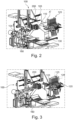
- Figure 1 shows schematically the translational movements of a transport unit belonging to a three-knife trimmer 100, the movements of which are carried out by two printed product-related movable transport units 101, 102, whereby these transport units, as will be explained in more detail later in the description of the other figures, are in operative connection with one another.
- the transport units have printed product-related grippers 103, 104 with clamping jaws at the end, which grasp the printed product A to be trimmed (this is often referred to as a book block, but at the same time other printed products, such as brochures, are also meant) on the spine side A R in a cyclical and force-locking manner one after the other.
- the transport units themselves carry out the following coordinated, control-supported translational movements with respect to the cutting locations 1, 2, 3, also called cutting stations:
- the first transport unit 101 actively takes over the printed product A at the first cutting location 1 after the first cutting operation has taken place there.
- This printed product A is then transferred by the first transport unit to the second cutting location 2 and, after the printed product has been delivered, returns to the starting position at the first cutting location 1 in order to be available there for a renewed takeover of a subsequently delivered printed product A after the first cutting operation has been carried out at the first cutting location 1.
- the second transport unit 102 takes over the printed product A immediately after the cutting operation has been completed at the second cutting location 2 and transfers it to the third cutting location 3, where the third cutting operation takes place.
- the second transport unit 102 then returns to the second cutting location 2, where another printed product A, delivered by the first transport unit and already trimmed, is already ready to be picked up and transferred to the third cutting location 3.
- the translational movements of the transport units 101, 102, with the integrated grippers 103, 104 cover two or three levels of the system, namely, in the first level X, the transfer of the printed product from one cutting location to the next is carried out; in the second level Y, the loading and unloading of the printed product at the respective cutting location is carried out.
- a third level Z (not shown in detail) is then used, in which a lateral adjustment (offset movement) takes place as required with respect to the stationary clamping elements related to the printed product at the respective cutting location of the three-knife trimmer 100.
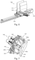
- Figures 2 and 3 show the three-knife trimmer 100 in a 3D representation.
- the book blocks A n are fed to the three-knife trimmer 100 lying down, with the book block spine first and at approximately equal intervals, via a conveyor belt 110.
- the approximately uniform feeding of the book blocks is achieved either by a timed feeding of the book blocks to the conveyor belt of the three-knife trimmer, or it is initiated by known devices on the conveyor belt that are part of the state of the art.
- the book blocks are fed to the conveyor belt 110 of the three-knife trimmer 100 with an irregular pitch.
- a timing device ensures that minimum pitches (distance from a leading book spine edge to the book spine edge of the next book block) are not undercut.
- a sensor detects the point in time at which a book block arrives at the conveyor belt of the three-knife trimmer. If the distance between the book blocks is now greater than the minimum pitch, the control system reduces the speed of the translational movements of the three-knife trimmer, whereupon the Three-knife trimmer is synchronized to the cycle of the delivered book block. If the division exceeds a maximum value, the control is programmed in such a way that it is able to generate idle cycles on the three-knife trimmer.
- the book blocks A n are aligned on the conveyor belt 110 by a fixed stop at the head or foot end. This can be done by a conveyor belt with slightly slanted conveyor rollers, or by other arrangements known from the state of the art.
- the other modules of the three-knife trimmer are arranged as shown in the Figures 2 and 3 are described in detail in the following figures.
- a flush slide 125 (see the Figures 3 and 14 ) is operatively connected to the insertion wheel 120 (feed device) and is intended to supplement the measures already explained in order to achieve a secure positioning of the book block relative to its stop surfaces.
- a stop surface is used for single book blocks, stacked book blocks or stacked brochures for the alignment of the spine of the printed products against a fixed support surface within the feed wheel 120.
- it must be ensured that the head and/or foot side of the printed products have a corresponding downward positioning in the transport direction before the first cutting operation.
- lateral means should preferably be provided before the first cutting operation, which ensure uniform alignment of the cutting edge of this package.
- the function of the insertion wheel 120 is therefore to pivot a foldable, rake-like guide against the book block so that after a 90° rotation, lying on its back, it cannot fan out and cannot fall over or tip over.
- the rake-like guide is coupled to the clamping unit, which temporarily clamps the book block in a position lying on its back and is kinematically designed so that this rake-like guide can be transferred to a position dependent on the book thickness.
- the clamping unit then opens slightly again so that the book block, following gravity, corrects the position of its book block spine against the stop surface of the insertion wheel.
- the clamping unit then closes again, whereupon the book block is held in a defined position. This procedure, which is optimized in itself, therefore guarantees that the book block spine assumes a defined position, which is crucial for the subsequent cutting operations.
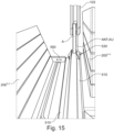
- the two front cover overhangs of the book block are supported in the pressure plane by the optimally angled brush combs (see Figures 14 , 15 ) or by other flexible mechanical or pneumatically controlled means, so that the resulting pressure force is transferred via cover overhangs to the body of the book block A, such that the latter then rests securely on the stop surface provided within the insertion wheel 120 or is otherwise positioned horizontally.
- this pressure force can also be used when it is necessary to achieve a flush position by means of an additional flush slide 126 (see Figures 3 and 15 ) to be able to exert a lateral pressure force on the head or foot of the printed product, with the aim of forming a uniform Level across all printed products of the package so that its edge can then be reliably detected by a sensor in order to be able to create the optimal positioning within the transport clamp device 130 so that the subsequent cutting operations (head and foot cuts) can be carried out correctly.
- the book blocks are pressed against a fixed stop 111 in the transport direction 112 by slightly inclined transport rollers 113 and then conveyed to the three-knife trimmer 100.
- the fixed stop 111 can be designed with a running belt (not shown in detail) or can also be just a fixed plate.
- the book blocks A n then reach a transfer position from which they are lifted, for example, by a rotating feed wheel 120 and brought into the operative position by rotation.
- FIG. 5 is achieved during a first 90° rotation of the insertion wheel 120, which fulfills the function of a feed device for a subsequent operation.
- a foldable, rake-like guide 121 swings against the book block A so that after the 90° rotation the latter lies on its spine and can no longer fan out or fall over.
- the rake-like guide 121 is coupled to a clamping unit 122, which briefly clamps the book block lying on its spine, the clamping unit being kinematically designed such that the book block can be transferred into a position dependent on the book thickness by the rake-like guide 121 belonging to the clamping unit.
- the clamping unit 122 then opens a little again so that the book block A or its book block spine, following gravity, hits the stop surface 123 of the insertion wheel 120 and then aligns itself there.
- the clamping unit 122 then closes again so that the book block is held in a defined position.
- the four-part insertion wheel 120 now rotates over two cycles by 90° each and transfers the printed product into a hanging position for further transport and further processing.
- the first rake-like guide 121 and a second, rake-like guide 124 which is operatively connected to it, are slightly pivoted away from the book block so that the components of the book block hang vertically downwards by gravity alone, while the book block is held in place by the clamping unit 122 at the spine.
- an open transport clamp (clearly visible in Figure 2 , Pos.130) moves horizontally in the direction of the book block spine over the book block and takes over a large area.
- this transport clamp 130 consists of two clamping jaws 131, 132, which operate in such a way that one clamping jaw 131 does not perform any stroke, while the other clamping jaw 132 performs the entire stroke movement. Together, the two clamping jaws 131, 132 perform two different offset movements, which are related in terms of transport technology in terms of whether the printed product (book block, brochure, etc.) is then transported in general or makes an empty run.
- the stroke of the two clamping jaws 131, 132 is individually designed, thus traveling the same or different paths until the final pressing position is reached.
- the transport clamp 130 can be moved horizontally by a linear movement device 133.
- a controlled drive (not shown in detail) moves the transport clamp 130 precisely to a transfer position that conforms to the book block. This always depends on the size of the cut that is made at the head or foot edge of the book block. Then, in the transfer position, the transport clamp 130 closes and clamps the book block between its front and back surfaces over a large area. Only the spine area and the section area of the book block to be trimmed remain free. For this, refer to the description of Figure 18
- the clamping unit 122 now opens and releases the book block spine.
- the transport clamp 130 then moves horizontally and transports the book block to the first cutting position (see also Figure 1 , Pos. 1), which consists of a modular multi-cutting device.
- the two clamping jaws 131, 132 can also be operated according to the following criteria: Each clamping jaw is directly or indirectly operatively connected to a drive that operates for the force-locking clamping effect.
- the clamping jaws guided by the drives have adjustable and/or predictively controlled stroke and force-locking profiles for any format of the printed product presented, so that the force-locking grip of the printed product by the clamping jaws is designed to be symmetrical or quasi-symmetrical with respect to its center line.
- the clamping jaws execute a mutually coordinated uniform, non-uniform or adaptive speed profile at least during the operative phase for exerting the clamping effect on the printed product. This operation can be provided for all clamping jaws that are operatively connected to one another and are components of the device underlying this.
- the modular cutting device 140 comprises three cutting stations, which consist of a first station 141 at the cutting location 1 (see Figure 1 ), a second cutting station 142 at cutting location 2 (see Figure 1 ) and a third cutting station 143 at cutting location 3 (see Figure 1 ).
- the book block is pressed by a pressing plate 145 and additionally by a pressing bar 144, such that it is clamped or pressed as much as possible by the aforementioned pressing elements 144, 145 in the area between the transport clamp and the cutting edge during the cutting operation.
- a knife 150b preferably moves along an oblique cut against a fixed cutting bar arranged diametrically opposite.
- the respective press bar 144 is therefore directly operatively connected to the respective cutting device 140, which is formed by the cutting blades 150a, 150b, 150c, whereby the press bar 144 ensures that the pressing force is exerted on the printed product which is indispensable for a clean cut.
- a certain force is built up on the press beam by building up a corresponding torque on the servo motor using a servo drive.
- the optimum pressing force required on the printed product is determined based on a thickness measurement, which can easily be done using stored control profiles. As a rule, a single calibration is sufficient to record a certain thickness variability of the printed products, provided that the underlying pressing force characteristic can be considered constant, because the differences in the book block thicknesses within a job are relatively small.
- the remaining two cutting locations are operated by knives 150a and 150c, which essentially follow the same pressure and cutting philosophy as explained above.
- the head area of the book block is cut (see also Figure 1 ).
- first gripper 103 engages during the cutting operation both in the vertical (Y-plane, see Figure 1 ) as well as in the horizontal direction (X-plane, see Figure 1 ) a movable, opened first gripper 103, which is directed vertically against the book block spine. After the first cut, the first gripper 103 takes over the book block from the spine, whereupon the transport clamp 130 opens. This then moves into the takeover position for the next book block. The first gripper 103 transports the book block from this first cutting operation ( Figure 1 , Pos. 1) vertically upwards (Y-plane) and then moves through a superimposed horizontal movement to the second cutting position ( Figure 1 , Pos. 2).
- the movement path of the first gripper 103 in the vertical direction is controlled by the machine control system depending on the width of the book block cut, whereby the movement path of the gripper in the horizontal direction relative to the book block can also be controlled individually, for example if a specific gripping position is desired. This is the case, for example, if the format and the sections to be cut off for the respective book block require an asymmetrical or quasi-asymmetrical clamping effect or a one-sided center of gravity-related clamping effect.
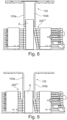
- the individual pressure bars 200 1-n close one after the other, starting at the top of the book block spine, so that this pressing process can simultaneously press out the air between the individual sheets to the cutting edge, while at the same time providing a holistic smoothing of the printed product.
- Figure 9 As can be seen furthermore, only as many pressing bars are used in the pressing process as are between the position of the gripper 103 with the respective clamping jaws 103a, 103b and the second cutting station 142 at the second cutting location 2 (see Figure 1 ) can be accommodated.
- clamping jaws 104a and 104b are assigned to the other gripper 104 (see Figure 1 ), which in turn enables a large-area pressing of the book block to be achieved.
- the front side of the book block is now cut, this takes place in a similar manner to the first and third cutting stations 141, 143 for the head and foot edges respectively.
- the first gripper 103 can release the book block and return to its take-over position (cutting location 1, Figure 1 ) for the transfer of the next book block.
- Figure 10 that ultimate force-related support of the book block A during the cutting operation to ensure that the cut can be carried out with the help of the knife 150b shown in the drawing. So if the pressure bars 200 1-n used (see the Figures 8, 9 ) have taken over the book block A from the gripper 103, the press bars (item 144) then engage, which exert the definitive pressing force on the book block in the immediate cutting area. This force must be predominant over other pressing forces so that the cut made by the knife 150b ensures a sharply cut cutting edge at right angles.
- the device exerting the pressing force consists on the other side of the book block of a fixed stop 152, as part of a pressing plate 145 (see also Figure 7 ), which is sometimes designed in such a way that it can also carry out a feeding movement, in the sense of the opposite movable press beam 144, whose pressure on the book block can be operated by a pressing bolt 151.
- This pressing bolt 151 can be driven, for example, by a motor, hydraulically, pneumatically, and thus exert the predetermined pressing force on the book block.
- the stop 152 can also be designed to be movable in a further embodiment in order to detect the thickness and/or the body consistency of the respective book block fed in, in other words, in accordance with the purpose, the leading edges of the fed book block will not experience any obstruction. This dynamic adjustment of the stop 152 can be carried out by the machine control already mentioned.
- the other press beams work according to the same principle (see Figure 7 , item 144) at the remaining cutting locations 1, 3, which now exert the pressing force in a vertical plane.
- the aim is to ensure a right-angled, sharply cut cutting edge.
- the second cutting operation front cut
- a second gripper 104 (see Figure 1 ) is moved into position, which grips the book block, in a similar way to the first gripper 103.
- the force-transmitting position of the second gripper 104 depends on the dimensions of the book block to be processed, and therefore essentially on the quality assurance of the cut to be made.
- the second gripper 104 is moved into a fixed gripping position so that for the subsequent third cutting operation (see Figure 1 , Pos. 3) the specified height of the book block is determined.
- the pressure bars of the pressure bar battery 200 open, whereupon the second gripper 104 grasps the printed product (book block, brochure, etc.), first lifting it vertically from the cutting position in order to then transfer it into a horizontal translation, finally placing it in the plane of the next cutting position in which the third trimming (normally the foot edge of the printed product) is carried out (see Figures 1 , 2 ), to lower it vertically.
- the gripper loaded by at least one book block carries out a lateral position-required offset movement relative to a pressing surface of the clamping device, as required.
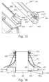
- Figure 13 shows the essential aspects concerning the implementation of the spread with regard to the flap fold AKF or the cover AU (see Figures 11 and 14 ), These are the elements from E1 and E2, (see Figure 12 ), which are figuratively recorded in the transport direction to the front cut.
- the oppositely arranged opening blades 530 form a spacing 560 from one another, the spacing of which ensures the unhindered passage of the transported book block, wherein this spacing can be changed by the delivery unit 550 according to the respective thickness of the book block, wherein, in order to ensure the safe passage of the book block, an addition of the spacing of approximately 5% compared to the measured thickness is used, bearing in mind the fact that the book block is not always present as a compact body.
- This inherently narrow spacing allowance is always indicated or necessary when it is a matter of simultaneously detecting double flap folds or covers on the book block, i.e. initiating a spreading on both sides of the book block.
- the control-controlled delivery unit 550 accesses both elements E1, E2 to change the spacing 560 (see Figure 12 ), namely on the opening blades 530 for forming the causal spread, and on the guides 510 provided for maintaining or increasing this spread.
- the pressing of the book block A or the book block body AK takes place by activating a certain number of pressing bars 200 1-n , whereby in addition to the pressing bars, pressing beams (see the Figures 10 and 14 , Pos. 152 and 144) are used, which exert the ultimate pressure in the area of the cutting operation.
- the two opening blades 530 have a largely vertical surface 531 on the inside of the passage 560, which extends over the entire length of the blade-like body. This allows the book block A to be opened from below via the translation 501 (see Figure 12 ) continuously, and this kind of delivery can be carried out up to the opening points 521 of the two opening blades 530 (see Figure 12 ). Sometimes it can be provided that the opening blade 540 is designed with a slight lateral offset to initiate the spreading of certain book blocks, the penetration of which between the flap fold or cover and the book block body can take place more easily.
- Figure 14 shows the state of the book block to be trimmed by trimming BS immediately before the cutting operation at the second cutting location 2 designed for carrying out the front cut, whereby the opening blade 530 is part of the element E1 (see Figure 12 ) represents the initiation of the spreading of the flap fold AKF or the cover AU, whereby the representation of the spreading in this figure is made from a different projection compared to the , whereby this representation has been included only for reasons of understanding.
- the subordinate element E2 with the guides 510 reference is made to the Figures 13 and 15 Essentially, this is directed Figure 14 , as regards the pressing of the book block, according to the operational processes according to Figure 10 .
- pressure bars 200 1-n which were originally provided according to Figure 10 are designed to carry out a front cut of a standard book block; however, in the presence of a flap fold or a cover, these pressure bars can only be used partially, i.e. sector by sector, and can therefore only develop their effective effect to the extent that the spread of the flap fold AKF or cover AU allows, so the spread flap fold and cover must not be affected by the cut BS of the book block body AK.
- the pressing force provided by drive A1 at the second cutting location 2 for carrying out the front cut (also applies to the other cutting locations 1, 3 of the device) for the cutting-compatible pressing of the printed product by the pressing beam 151 and the cutting force provided by drive A2 for carrying out the cutting operation by the cutting device 150b are provided by a common drive unit.
- the pressing force provided by drive A1 for the cutting-compatible pressing of the printed product and the cutting force provided by drive A2 for carrying out the cutting operation should be provided by individual drive units.
- the latter arrangement has the advantage that individual adjustments can be made before or continuously during operation.
- Figure 15 is a general view of the second cutting location 2, up to the front cut, from which figure the execution of the spreading of a book block A, which is gripped by gripper 103 (see Figure 1 ) is force-fitted and transferred to the opening blade 530 as a component of the first element E1 (see 12), whereby this only involves the spreading of a flap fold AKF or a cover AU on one side of the book block. It is also shown that the arrangements are intended for a two-sided spreading. Also shown here is the point of action of the delivery unit 550, which determines the spacing of the opening blade 530 belonging to the first element E1 and the guides 510 belonging to the second element E2 (see Figure 12 ) takes over. For the operation of these elements E1, E2, please refer to the explanations under Figure 12 For the operation of the pressure bars 200 1-n' , instead of many, the Figures 8-10 and 14. Furthermore, Figure 15 completely self-explanatory.
- Figure 16 shows in block diagram form the process sequences when carrying out a standard single cut at each cutting location 1, 2, 3, as well as those sequences which involve the implementation of a second, possibly further subsequent partial cut.
- the printed product A that is fed in is aligned in the feed wheel 120 for the immediately following cutting operation, such that the first one of the transport unit 101 is grasped on the spine side for further transport after this first cutting operation, whereby the top edge of the printed product is generally processed at the first cutting location 1, but it is not excluded that this first cutting operation can affect the foot edge.
- the clamping device 130 and the press bar 144 are generally activated, whereby the cutting knife 150a carries out the cutting operation.
- the sequences taking place within this first cutting location 1 reference is made to the explanations in the previous figures.
- a quality check 400 is carried out, which focuses on the quality of the cut and also checks whether the thickness of the cut section corresponds to the values specified in advance. At the same time, the integrity of the spine of the book block is also checked.
- the means used for these tests include contact-based and contact-free sensors, which integrally record the actual state of the printed product (book block, brochure, etc.) after each cutting operation and forward the information derived from this to the control unit, and also sensors of the newer generation, which ensure sensor-based production by being able to control, regulate and optimize the focused processes for quality.
- These sensors must have excellent data quality for the quality tests underlying them and are preferably based on inductive and photoelectric technologies. In general, the measured variable should be converted into an internal signal by the physical measuring principle of the sensor element. After If required, individual electronic processing is then provided, whereby a measured value is then available at the output as an electrically and/or electronically usable signal.
- the first cut T 1-1 is basically repeated as part of the process, i.e. the necessary pressing of the printed product is carried out using the same means 130 and 144 and the cutting operation is carried out using the same cutting blade 150a.
- What is also added is a coordinated kinematic procedure which ensures that the additional section of the head edge of the book block A to be trimmed is pushed forward relative to the fixed cutting blade 150a.
- the book block A is briefly clamped by the clamping jaws of the gripper 103 of the transport unit 101 of the transport unit, whereupon the clamping jaws 131, 132 belonging to a clamping device 130, also called a transport clamp, open slightly so that the book block A is positioned without pressure relative to the aforementioned clamping jaws 131, 132.
- a clamping device 130 also called a transport clamp
- the clamping jaws belonging to the gripper 103 of the transport unit 101 of the transport device now exert a force connection on the book block A at the location of the first partial cut T 1-1 , which clamping jaws, in operative connection with this transport unit, give the book block A an intertemporal local positioning when the clamping jaws 131, 132 of the transport clamp 130 are open.
- the opened clamping jaws 131, 132 of the transport clamp 130 move backwards relative to the cutting blade 150a by a length amount, whereby this length amount corresponds to the width of the second partial cut T 1 - 2.
- the clamping jaws 131, 132 of the transport clamp 130 exert a force connection on the book block A again, with the coordinated opening of the clamping jaws of the gripper 103 of the transport unit 101 of the transport unit.
- These clamping jaws 131, 132 of the transport clamp 130 now move the clamped printed product A forwards by the relevant length amount for the second partial cut T 1-2 , such that the book block A is thereby transferred back into the cutting position.
- the book block A is pressed by the cutting location-related press bar 144, which exerts the ultimate pressing force on the book block.
- the press bar 144 moves back in time with the cutting knife 150a, whereupon the clamping jaws 131, 132 of the transport clamp 130 open, and the book block A is then transported further by the transport unit 101 of the transport device.
- the quality-checking sensors 400 also remain in use during and after the end of this cutting operation until they take over the quality check by sensors at the next cutting station, which ensures that the quality is carried out according to uniform criteria across all cutting operations.
- the cutting operations relating to the third cutting location 3 (T 3-1 , T 3-2 , etc.) are carried out in a similar way, as can be seen from the block diagram according to Figure 16 emerges.
- the rotating discharge device (four-clamp system) 160 and thus also the clamp 161 with the book block move orthogonally to the knife movement away from the cutting device.
- the rotating four-clamp system 160 rotates by 90° during each cycle (see Figure 17 ).
- the four-clamp system 160 shown shows the position of the clamp 161 in the cutting position 162, in which a movable jaw 163 is still open. Another clamp acts within the discharge position 164. In this position, the book block A can be removed.
- the functioning of the four-clamp system 160 ensures that the book block A is held in place during the cutting process at the third cutting location 3 (see Figures 1 , 7 ) and the rotational movement of the four-clamp system is pressed between the movable jaw 163 and the fixed jaw 165.
- One or the other specification can be specifically taken into account within this quadrant, depending on the respective space conditions available during rotation.
- the removal device can be, for example, a conveyor belt equipped with movable rollers for conveying the book block.
- Other devices known from the prior art can also be provided.
- Figure 19 shows the effect of the various pressing elements (clamping devices) on the printed product, which, in relation to the cutting location 2, is exerted by the various clamping devices 103, 200, 144, whereby at this cutting location one clamping device consists of a pressure bar battery 200.
- the pressing forces shown in the diagram within the various clamping devices must also only be understood as a qualitative representation.
- the clamping force of the gripper 103 which is made available for the transport 210 of the printed product from one cutting location to the next, is in itself smaller than the cutting location-related clamping forces 200 and 144, since this is only a force which only has to be sufficient for the secure clamping effect of the book block during transport.
- the clamping force of the pressure bars 200 1-n belonging to the pressure bar battery is then built up simultaneously or subsequently, so that the clamping force of the gripper 103 immediately decreases 211 (reduction point) as soon as the final clamping force of the pressure bars on the book block is reached.
- the extent to which the clamping force of the gripper on the book block decreases is set individually and also depends on the weight of the respective book block.
- the final clamping force on the book block, which is important for the cutting quality, is then exerted by the previously mentioned press bar 144, which takes up its position parallel to the plane of the cutting blade.
- the press bar 144 preferably develops its greatest pressing force in operative connection with the cutting operation, which is variable and phase-shifted 212 (engagement plane) compared to the other clamping devices, as can be seen from the parallel interruption lines 212a, 212b (phase shift interval).
- the knife carries out the cutting operation 213.
- the pressing beam 144 then remains briefly in the cutting plane 215 until the clamping force of the gripper has built up to such an extent that a safe further transport 214 of the book block is ensured.
- all of the pressing elements 103, 104, 144, 200, .... operating within the device, whether they act directly or indirectly on the printed product or the book block, are supplemented with built-in hydraulically and/or pneumatically operated additional elements which serve to support the opening and closing of the same.
- the normally operating closing and opening mechanisms of the pressing elements of the device are permanently or optionally supplemented with further pneumatically and/or hydraulically operated additional elements which are able to implement a maximized acceleration of the respective movement of the pressing elements in both directions, i.e. both when closing and when opening, regardless of the frictional connection implemented there, in this case it is a question of a uniform or exponential acceleration.
- this Figure 19 shows symbolically how the mutually coordinated uniform, non-uniform or adaptive speed and/or
- the movement profile of both pressing elements of a clamping device can also be designed for a one-sided pressing force exerted by the pressing beam 144, in that the force provision for the knife 150b is no longer coupled with that for the pressing beam 144, but rather the latter exerts its pressing force autonomously on the book block, as is symbolized by position 251 (see also Figure 7 ).
- the pressing force exerted by the press beam on the book block can then be provided according to individual criteria.
- the speed profile of the press beam 144 can be transferred to a different mode immediately after the first contact with the book block.
- publication EP 1 647 373 A1 represent an integral part of this description, especially when it comes to showing how the coordination of the drives for providing the pressing force can be carried out in conjunction with the process dynamics of the cutting device and knife dynamics.
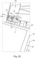
- Figure 20 shows the configuration of a flush slide 125 (see also Figure 3 ).
- This consists of a support plate 180 acting from above, which carries brush bodies 181, 182 on the printed product side, which exert pressure on the front end 183 protruding above the printed product A, so that the back of the printed product matches the support surface within the insertion wheel 120. Since the end 184 of the cover is in the same alignment plane on the front, they can be better seen under positions 185 and 186 (head or foot of the printed product A).
- Both brush bodies 181 and 182 each consist of two partial brush bodies 181a, 181b; 182a, 182b, which are at an angle to each other, such that the respective folded end is gripped in a wedge shape and pressed downwards in a parallel manner, whereby the folded ends do not experience any harmful bulging.
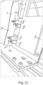
- Figure 21 shows the configuration of another flush slide 126 (see also Figure 3 ).
- This consists of a receiving plate 190 acting on the head or foot side, which carries brush bodies 191, 192 on the printed product side, which exert pressure on the head or foot side fold ends 184, 185 protruding above the printed product A, so that the printed product A is positioned accordingly for the cutting operations.
- the overhanging fold ends can be seen here in relation to the back section 193 of the printed product A.
- Both brush bodies 191 and 192 each consist of two partial brush bodies 191a, 191b; 192a, 192b, which are at an angle to one another, such that the respective fold end is gripped by the brush bodies in a wedge shape and the entire printed product body assumes a lateral positioning, so that the fold ends do not experience any harmful bulging.
- Figure 22 shows a further transport device 300 of the printed products from one cutting location 1 to the next 2 and from there to a third 3.
- the cutting operations carried out at these cutting locations are the same as those under Figure 1 described.
- the main difference compared to transport dynamics according to Figure 1 consists in the fact that at least three transport units with the respective grippers 101/103 are operationally used along a substantially elliptical path 301, whereby this functional circulating path consists of a front track 303 and a substantially parallel rear track 304, whereby the two tracks merge into one another by means of a circumferential curve 305, 306.
- the front track serves to guide the transport units following one another in a cycle in a straight line or quasi-straight line along the cutting locations 1, 2, 3.
- the number of transport units along the path depends on the maximum permissible cycle rate, ie each transport unit takes over a printed product, and guides the printed product one after the other and without transfer over the three underlying cutting locations 1, 2, 3.
- the cycle is designed so that the transport units follow one another closely and the distance between them depends on the time required for the individual cutting operations, which means that more than three transport units can generally be used.
- a reduction in the number of transport units can be achieved, for example, if they are subjected to acceleration along the rear path 304 between the last cutting location 3 and the first cutting location 1.
- transport units in operational use are shown hatched, while the other transport units are unloaded, i.e. they move downstream of the discharge device 160, i.e. they are each on their way to the delivery device 120 for the renewed receipt of a printed product.
- Such a transport variant characterized by an elliptical path 301 can be used well for central trimming of the printed products, i.e. when the three cutting operations are to be carried out at a single cutting location, i.e. when the print product is taken over, fed to the central cutting location and then delivered by one and the same transport unit.
- Such central trimming could advantageously be carried out within the second cutting station 2 described above.
- the transport units in use should then advantageously not return to the delivery device 120 via the front track 303, but rather they should move along the rear track 304, so as not to hinder the production flow.
- opening means are arranged in the area of the front cut to capture the flap fold or envelope to produce a spread, which do not hinder the entire cutting process across all edges of the printed product, in such a way that these opening means either operate from a fixed local positioning or are switched on and off intertemporarily.
- the described three-knife trimmer 100 has the following advantages over the known three-knife trimmers: During the cutting process, the book block is pressed almost over its entire surface by clamps or pressure bar batteries. Only in one area of the spine does the book block have an open area M1, which serves to capture the book block itself. This is not critical in itself because the bound book block holds together sufficiently in this area and in the cutting area the pressure bars within the respective cutting station of the cutting devices support the book block. The full-surface pressing of the book block leads to a high cutting quality.
- Full-surface pressing is achieved in a simple manner. No webs, support elements or support strips need to be adjusted depending on the format. This means that a high cycle rate and thus a high performance of the three-knife trimmer can be achieved.
- the three-knife trimmer according to the invention allows the book block to be supplied hanging to the individual cutting stations 141, 142, 143 (see Figure 7 ), there are no provisions for supporting the sides at the transfer points in the transport system of the book block is necessary. Since the book blocks are not transported lying down, the book pages do not bend if the support surfaces are not full-surface between the support points, which means that they cannot get caught at the transfer points.
- the three cutting stations 141, 142, 143 of the cutting device are arranged in a U-shape with the open side of the U facing downwards.
- the section of book block to be cut off is carried out in all three cutting operations in operative connection with the press beams 144 (see Figure 7 , and especially Figure 10 ) against the inside of the U-shape.
- This means that all three cut-off sections can be successfully "discharged” using a single section disposal device arranged underneath. These sections fall downwards due to gravity without the need for any additional aids, where they can then be easily collected. This hanging transport position proves to be optimal when it comes to spreading the flap fold or the cover at the second cutting station.
- the cover protrudes more or less from it.
- the book blocks are produced with a fixed cover overhang on one side and a variable overhang on the other side.
- the uncut book block or the uncut brochures are aligned at the foot or head edge and the processed spine edge. This means that the variable cover overhangs in the book block height and the book width are not important.
- the product data of the three-knife trimmer control must be known, from which the necessary movements of the transport elements can be calculated so that a cut book is produced that has the desired format dimensions.
- This data can be transmitted to the control in a variety of ways.
- Each book block or brochure is marked with an identification feature.
- a feature reader at the entrance to the three-knife trimmer reads the identification feature (e.g. one- or two-dimensional barcode, RFID chip, character, image, etc.) and transmits the information recorded from it to the control system, which determines the machine cycle allocation.
- the information recorded can, for example, map the cut printed product dimensions, or at the same time determine a missing allocation, whereupon profiles stored in the database are automatically used.
- the book blocks are fed to the three-knife trimmer in a timed manner.
- the three-knife trimmer control is supplied with the information required to cut the book block to the correct dimensions.
- the data supplied with the book block can be compared with the database.
- Another possibility is that data is fed to the three-knife trimmer that records the order in which the book blocks are fed in.
- the three-knife trimmer processes the book blocks fed in in the specified order, with any deviations from this being recorded simultaneously and implemented accordingly in the control system. This is particularly true if the system is operated entirely according to digitization principles, i.e. if different types of book blocks are to be trimmed to different dimensions throughout.
- the covers connected to the book block are measured using sensors before or in the three-knife trimmer.
- the cover By measuring the width of the cover, which corresponds to the distance from the spine to the edge of the cover running parallel to the spine, the book block can be positioned and cut according to the measured cover width during the front cut.
- the width of the trimmed book block can therefore deviate from the target value stored in the control system, but the cover protrudes the same amount over the book block at the front cut on all finished cut books or is flush with it.
Landscapes
- Engineering & Computer Science (AREA)
- Mechanical Engineering (AREA)
- Life Sciences & Earth Sciences (AREA)
- Forests & Forestry (AREA)
- Making Paper Articles (AREA)
- Perforating, Stamping-Out Or Severing By Means Other Than Cutting (AREA)
- Details Of Cutting Devices (AREA)
- Nonmetal Cutting Devices (AREA)
- Folding Of Thin Sheet-Like Materials, Special Discharging Devices, And Others (AREA)
Applications Claiming Priority (1)
| Application Number | Priority Date | Filing Date | Title |
|---|---|---|---|
| DE102023117233.6A DE102023117233A1 (de) | 2023-06-29 | 2023-06-29 | Einrichtung und Verfahren zur Durchführung von Schneidoperationen an Formatkanten mindestens eines mit einem Klappenfalz oder Umschlag ausgebildeten Druckprodukts |
Publications (1)
| Publication Number | Publication Date |
|---|---|
| EP4484097A1 true EP4484097A1 (fr) | 2025-01-01 |
Family
ID=91581889
Family Applications (1)
| Application Number | Title | Priority Date | Filing Date |
|---|---|---|---|
| EP24182480.4A Pending EP4484097A1 (fr) | 2023-06-29 | 2024-06-17 | Dispositif et procédé pour effectuer des opérations de coupe sur des bords de format d'au moins un produit d'impression formé avec un pli de rabat ou une enveloppe |
Country Status (5)
| Country | Link |
|---|---|
| US (1) | US20250001636A1 (fr) |
| EP (1) | EP4484097A1 (fr) |
| JP (1) | JP2025009950A (fr) |
| CN (1) | CN119217458A (fr) |
| DE (1) | DE102023117233A1 (fr) |
Citations (4)
| Publication number | Priority date | Publication date | Assignee | Title |
|---|---|---|---|---|
| EP1647373A1 (fr) | 2004-10-18 | 2006-04-19 | Müller Martini Holding AG | Procédure de découpe de plusieurs côtés d'un produit imprimé |
| DE102005033787A1 (de) * | 2005-07-20 | 2007-01-25 | Rathert, Horst, Dipl.-Ing. | Dreischneider zum Beschnitt von Broschuren mit eingeschlagenen Klappen |
| EP3285978B1 (fr) | 2015-04-21 | 2019-03-06 | Müller Martini Holding AG | Dispositif pour effectuer des operations de coupe de bords de format ouvert d'un produit d'impression |
| EP3482892A2 (fr) | 2017-11-08 | 2019-05-15 | Müller Martini Holding AG | Dispositif pour l'exécution d'opérations de coupe de bords de format ouverts d'un produit imprimé |
Family Cites Families (3)
| Publication number | Priority date | Publication date | Assignee | Title |
|---|---|---|---|---|
| US4496140A (en) * | 1983-09-19 | 1985-01-29 | Stobb, Inc. | Apparatus for handling a signature |
| DE19843011C2 (de) * | 1998-09-21 | 2003-02-27 | Perfecta Schneidemaschinenwerk Gmbh | Verfahren und Vorrichtung zum mindestens vierseitigen Beschneiden von Schneidgut aus Papierwerkstoffen oder papierwerkstoffähnlichen, stapelbaren Materialien |
| EP1504860A1 (fr) * | 2003-08-07 | 2005-02-09 | Müller Martini Holding AG | Méthode et dispositif d'ébarbage des bords latéraux de produits imprimés |
-
2023
- 2023-06-29 DE DE102023117233.6A patent/DE102023117233A1/de active Pending
-
2024
- 2024-06-17 EP EP24182480.4A patent/EP4484097A1/fr active Pending
- 2024-06-20 CN CN202410798945.6A patent/CN119217458A/zh active Pending
- 2024-06-25 JP JP2024101661A patent/JP2025009950A/ja active Pending
- 2024-06-26 US US18/754,230 patent/US20250001636A1/en active Pending
Patent Citations (4)
| Publication number | Priority date | Publication date | Assignee | Title |
|---|---|---|---|---|
| EP1647373A1 (fr) | 2004-10-18 | 2006-04-19 | Müller Martini Holding AG | Procédure de découpe de plusieurs côtés d'un produit imprimé |
| DE102005033787A1 (de) * | 2005-07-20 | 2007-01-25 | Rathert, Horst, Dipl.-Ing. | Dreischneider zum Beschnitt von Broschuren mit eingeschlagenen Klappen |
| EP3285978B1 (fr) | 2015-04-21 | 2019-03-06 | Müller Martini Holding AG | Dispositif pour effectuer des operations de coupe de bords de format ouvert d'un produit d'impression |
| EP3482892A2 (fr) | 2017-11-08 | 2019-05-15 | Müller Martini Holding AG | Dispositif pour l'exécution d'opérations de coupe de bords de format ouverts d'un produit imprimé |
Also Published As
| Publication number | Publication date |
|---|---|
| JP2025009950A (ja) | 2025-01-20 |
| US20250001636A1 (en) | 2025-01-02 |
| CN119217458A (zh) | 2024-12-31 |
| DE102023117233A1 (de) | 2025-01-02 |
Similar Documents
| Publication | Publication Date | Title |
|---|---|---|
| EP2113392B1 (fr) | Dispositif de transport destiné au traitement des blocs de livre et dispositif de reliure par collage | |
| EP3285978B1 (fr) | Dispositif pour effectuer des operations de coupe de bords de format ouvert d'un produit d'impression | |
| EP3482892B1 (fr) | Procédure pour l'exécution d'opérations de coupe de bords de format ouverts d'un produit imprimé | |
| EP2447197B1 (fr) | Dispositif et procédé de renversement de piles de matériaux en feuilles | |
| DE102007032604B4 (de) | Klebebinder | |
| EP2508353A2 (fr) | Machine destinée à la fabrication de livres, notamment livres photo et/ou livres illustrés | |
| EP2377688B1 (fr) | Dispositif de fabrication de produits à reliure adhésive | |
| DE69702274T2 (de) | Vorrichtung zum Sammeln und Stapeln von Schichtwerkstoffen, und ein Stapelverfahren | |
| EP0091714A1 (fr) | Méthode et appareil pour la fabrication des papiers-valeur imprimés, numérotés et découpés | |
| EP1690696A1 (fr) | Dispositif et procédé pour l'endossage mécanique des signatures | |
| EP2397339B1 (fr) | Procédé et dispositif destinés à la fabrication de couvertures de livre | |
| EP0675005A1 (fr) | Dispositif pour la reliure adhésive de produits imprimés | |
| EP1764232B1 (fr) | Méthode et dispositif pour la fabrication des journaux imprimés de façon numérique | |
| EP1745920B1 (fr) | Dispositif pour couper et joindre des section d'une bande collante, en particulier bande renforcée, de préférence bande renforcée textile | |
| EP1647373B1 (fr) | Procédure de découpe de plusieurs côtés d'un produit imprimé | |
| DE102012207295B4 (de) | Verfahren und Vorrichtung zur Herstellung von Büchern mit Drahtkamm- oder Spiralbindung oder anderen vergleichbaren Bindungen | |
| EP1674285B1 (fr) | Machine pour former et pincer des livres | |
| EP2202158A1 (fr) | Dispositif de cerclage et son procédé de fonctionnement | |
| CH694504A5 (de) | Verfahren zum Schneiden von Blechtafeln zu Blechstreifen sowie Schneidevorrichtung zu dessen Durchfuehrung. | |
| EP0591099A1 (fr) | Procédé et dispositif pour fabriquer des piles de produits en papier liées | |
| EP4484097A1 (fr) | Dispositif et procédé pour effectuer des opérations de coupe sur des bords de format d'au moins un produit d'impression formé avec un pli de rabat ou une enveloppe | |
| DE3427570A1 (de) | Vorrichtung zum falzen und weiterverarbeiten von druckexemplaren | |
| EP2452904B1 (fr) | Dispositif de transport de piles de documents, notamment de documents de sécurité, vers des stations de reliure | |
| DE102019126034A1 (de) | Vorrichtung und Verfahren zur automatisierten Herstellung von Bucheinbanddecken und/oder Schachteldecken | |
| EP3290223A1 (fr) | Dispositif et procédé d'alignement d'un bloc-livre comprenant des feuilles individuelles et/ou des cahiers |
Legal Events
| Date | Code | Title | Description |
|---|---|---|---|
| PUAI | Public reference made under article 153(3) epc to a published international application that has entered the european phase |
Free format text: ORIGINAL CODE: 0009012 |
|
| STAA | Information on the status of an ep patent application or granted ep patent |
Free format text: STATUS: THE APPLICATION HAS BEEN PUBLISHED |
|
| AK | Designated contracting states |
Kind code of ref document: A1 Designated state(s): AL AT BE BG CH CY CZ DE DK EE ES FI FR GB GR HR HU IE IS IT LI LT LU LV MC ME MK MT NL NO PL PT RO RS SE SI SK SM TR |
|
| STAA | Information on the status of an ep patent application or granted ep patent |
Free format text: STATUS: REQUEST FOR EXAMINATION WAS MADE |
|
| 17P | Request for examination filed |
Effective date: 20250612 |