EP4484277A1 - Vorrichtung zum abdichten einer verbindung zwischen einem flügelkasten und einem zentralen rumpf eines flugzeugs, verfahren zum abdichten und entsprechendes luftfahrzeug - Google Patents
Vorrichtung zum abdichten einer verbindung zwischen einem flügelkasten und einem zentralen rumpf eines flugzeugs, verfahren zum abdichten und entsprechendes luftfahrzeug Download PDFInfo
- Publication number
- EP4484277A1 EP4484277A1 EP24184217.8A EP24184217A EP4484277A1 EP 4484277 A1 EP4484277 A1 EP 4484277A1 EP 24184217 A EP24184217 A EP 24184217A EP 4484277 A1 EP4484277 A1 EP 4484277A1
- Authority
- EP
- European Patent Office
- Prior art keywords
- wall
- sealing
- deformable
- aircraft
- wing box
- Prior art date
- Legal status (The legal status is an assumption and is not a legal conclusion. Google has not performed a legal analysis and makes no representation as to the accuracy of the status listed.)
- Pending
Links
Images


Classifications
-
- B—PERFORMING OPERATIONS; TRANSPORTING
- B64—AIRCRAFT; AVIATION; COSMONAUTICS
- B64C—AEROPLANES; HELICOPTERS
- B64C1/00—Fuselages; Constructional features common to fuselages, wings, stabilising surfaces or the like
- B64C1/16—Fuselages; Constructional features common to fuselages, wings, stabilising surfaces or the like specially adapted for mounting power plant
-
- B—PERFORMING OPERATIONS; TRANSPORTING
- B64—AIRCRAFT; AVIATION; COSMONAUTICS
- B64C—AEROPLANES; HELICOPTERS
- B64C1/00—Fuselages; Constructional features common to fuselages, wings, stabilising surfaces or the like
- B64C1/26—Attaching the wing or tail units or stabilising surfaces
-
- B—PERFORMING OPERATIONS; TRANSPORTING
- B64—AIRCRAFT; AVIATION; COSMONAUTICS
- B64D—EQUIPMENT FOR FITTING IN OR TO AIRCRAFT; FLIGHT SUITS; PARACHUTES; ARRANGEMENT OR MOUNTING OF POWER PLANTS OR PROPULSION TRANSMISSIONS IN AIRCRAFT
- B64D37/00—Arrangements in connection with fuel supply for power plant
- B64D37/02—Tanks
- B64D37/04—Arrangement thereof in or on aircraft
-
- B—PERFORMING OPERATIONS; TRANSPORTING
- B64—AIRCRAFT; AVIATION; COSMONAUTICS
- B64D—EQUIPMENT FOR FITTING IN OR TO AIRCRAFT; FLIGHT SUITS; PARACHUTES; ARRANGEMENT OR MOUNTING OF POWER PLANTS OR PROPULSION TRANSMISSIONS IN AIRCRAFT
- B64D47/00—Equipment not otherwise provided for
-
- F—MECHANICAL ENGINEERING; LIGHTING; HEATING; WEAPONS; BLASTING
- F16—ENGINEERING ELEMENTS AND UNITS; GENERAL MEASURES FOR PRODUCING AND MAINTAINING EFFECTIVE FUNCTIONING OF MACHINES OR INSTALLATIONS; THERMAL INSULATION IN GENERAL
- F16J—PISTONS; CYLINDERS; SEALINGS
- F16J15/00—Sealings
- F16J15/02—Sealings between relatively-stationary surfaces
- F16J15/021—Sealings between relatively-stationary surfaces with elastic packing
- F16J15/028—Sealings between relatively-stationary surfaces with elastic packing the packing being mechanically expanded against the sealing surface
-
- F—MECHANICAL ENGINEERING; LIGHTING; HEATING; WEAPONS; BLASTING
- F16—ENGINEERING ELEMENTS AND UNITS; GENERAL MEASURES FOR PRODUCING AND MAINTAINING EFFECTIVE FUNCTIONING OF MACHINES OR INSTALLATIONS; THERMAL INSULATION IN GENERAL
- F16L—PIPES; JOINTS OR FITTINGS FOR PIPES; SUPPORTS FOR PIPES, CABLES OR PROTECTIVE TUBING; MEANS FOR THERMAL INSULATION IN GENERAL
- F16L55/00—Devices or appurtenances for use in, or in connection with, pipes or pipe systems
- F16L55/10—Means for stopping flow in pipes or hoses
- F16L55/12—Means for stopping flow in pipes or hoses by introducing into the pipe a member expandable in situ
- F16L55/128—Means for stopping flow in pipes or hoses by introducing into the pipe a member expandable in situ introduced axially into the pipe or hose
- F16L55/132—Means for stopping flow in pipes or hoses by introducing into the pipe a member expandable in situ introduced axially into the pipe or hose the closure device being a plug fixed by radially deforming the packing
Definitions
- the present invention relates to a device for sealing a junction located between a wing box and a central fuselage of an aircraft, in particular for sealing a fuel tank formed in the wing box.
- the invention also relates to a method for sealing such a junction and an aircraft comprising at least one such sealing device.
- a known technique for sealing the junction between the wing box and the central fuselage of the aircraft consists of injecting a sealant containing small foam particles into these openings.
- a sealant containing small foam particles into these openings.
- an operator at each opening left free between the wing and the central fuselage, an operator must first place a blocking element ensuring the flow of the sealant in a single direction when injecting it. He must then place an adhesive sealant inlet element comprising a hole for receiving the injection nozzle of the sealant injection gun to guide the sealant towards the inside of the opening. Finally, the operator can inject the sealant into the opening using the injection gun.
- a disadvantage of this technique is that the sealant must be injected by an operator from inside the wing box.
- the space within the wing box is very restricted and the openings to be sealed with the sealant are difficult to access for the operator, who must therefore inject the product into very uncomfortable positions.
- the height of the wings is set to decrease in order to improve the performance of aircraft wings. This technique is therefore likely to be increasingly complex to implement and the ergonomic issues for operators are likely to increase significantly. This technique is therefore not satisfactory.
- An object of the present invention is to propose a device for sealing a junction located between at least one wall of a wing box of an aircraft and at least one wall of a central fuselage of said aircraft which is reliable and simple to implement.
- Said clamping means are movable between a rest position in which said clamping means do not clamp the first rigid end element and the second rigid end element towards each other and leave said at least one deformable element in an initial undeformed position, and a clamping position in which said clamping means clamp the first rigid end element and the second rigid end element towards each other by deforming by crushing said at least one element deformable until said at least one deformable element is intended to be pressed against said at least one wall of said wing box and against said at least one wall of the central fuselage.
- Said rigid end element against which said nut is arranged comprises a housing for receiving and holding said nut preventing rotation of said nut relative to said rigid end element during tightening and loosening of the tightening means.
- Said device further comprises a sealing product intended to be arranged in said junction between said at least one wall of said wing box and said at least one wall of said central fuselage, said sealing product being configured to seal spaces left free between said at least one deformable element and said at least one wall of said wing box and/or said at least one wall of the central fuselage.
- Such a sealing device makes it possible to ensure the sealing of a junction while allowing simple and easy installation from the outside of the aircraft.
- a device can easily be adapted to different shapes of junction to be sealed.
- said device comprises a sealing product arranged at least in part around said at least one deformable element, at least when said clamping means of said device are in said clamping position, said sealing product being configured to seal spaces left free between said at least one deformable element and said at least one wall of said wing box and/or said at least one wall of the central fuselage.
- said sealing device further comprises at least one intermediate rigid element arranged in said at least one deformable element or between at least two deformable elements when said device comprises a plurality of deformable elements, said at least one intermediate rigid element comprising a fourth bore extending coaxially with said first bore, into which said threaded rod is threaded.
- said at least one intermediate rigid element has a polygonal section, said at least one deformable element comprising a recess having a section of shape complementary to said at least one intermediate rigid element, or said at least two deformable elements receiving said at least one intermediate rigid element comprising faces having shapes complementary to said at least one intermediate rigid element.
- the invention also provides an aircraft comprising a wing box having at least one wall, a central fuselage having at least one wall and at least one device sealing as previously described, arranged between said at least one wall of the wing box and said at least one wall of the central fuselage.
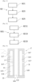
- FIG. 1 shows an aircraft 9 which comprises a central fuselage 92 and two wing boxes 91 (namely a port wing box and a starboard wing box) which are assembled to the central fuselage 92, each at a junction 93.
- the present invention implements a sealing device 1, 1' which makes it possible to ensure optimum sealing of the junction 93 while facilitating its installation which can, preferably, be carried out from the outside of the aircraft 9.
- the sealing device 1, 1' is intended to be implemented between at least one wall 911 of the wing box 91 and at least one wall 921 of the central fuselage 92 (as shown in the following figures).
- THE Fig. 2 to 5 illustrate a first embodiment of a sealing device 1 for sealing the junction 93 between a wing box 91 and a central fuselage 92 of an aircraft 9, and more particularly here between a wall 911 of the wing box 91 and a wall 921 of the central fuselage 92.
- the sealing device 1 comprises a first rigid end element 13 and a second rigid end element 15 respectively comprising a first bore 131 and a second bore 151 which extend coaxially.
- One of the rigid end elements 13 and 15 comprises a housing 153 for receiving and holding a nut 171 described below.
- the housing 153 extends coaxially with the first 131 and second 151 bores.
- the geometry of the rigid end elements 13 and 15 depends on the geometry of the section of the cavity to be sealed. For example, if the cavity has a circular section, . it is preferable for the rigid end members 13 and 15 to be generally in the form of washers, whereas if the cavity has a rectangular cross-section, it is preferable for the rigid end members 13 and 15 to also have a rectangular shape.
- the rigid end members 13 and 15 are for example made of metal or a rigid plastic that is not or only slightly deformable in order to allow transmission optimum clamping force of the clamping means 17 on at least one deformable element 11 (described below).
- the installation 811 of the sealing product 2 is, in the example illustrated on the Figs. 4 and 5 , carried out in the space left free between the wing box 91 and the fuselage 92 using a corner connector 932 comprising a seal 931 covering at least in part the junction 93 between the wing box 91 and the central fuselage 92.
- This positioning 811 of the sealing product 2 prior to the insertion of the device 1 into the junction 93, allows the sealing product 2 to propagate, that is to say to flow, around the deformable elements 11 of the sealing device 1 once the latter is positioned in the junction 93.
- At least one of the at least one deformable element 11 comprises at least one deformable cavity 113 containing the sealing product 2.
- a cavity 113 is deformable in the sense that its internal volume is reduced when the clamping means 17 are tightened.
- Each cavity 113 is connected to the exterior 115 of the deformable element 11 in which it is located by at least one channel 117. It is also conceivable that cavities 113 are connected to each other.
- the intermediate rigid element 19 has a generally octagonal shape and separates the two parts 11a, 11b of the deformable element 11.
- the faces of the two parts 11a, 11b located opposite each other and cooperating with the intermediate rigid element 19 each have a recess 119 of a shape corresponding to the intermediate rigid element 19 when the sealing device 1' is in the rest position, in particular.
- the sealing product 2 is contained in a cavity 113 formed between the two parts 11a, 11b of the deformable element 11.
- the intermediate rigid element 19 is arranged within this cavity 113.
- the channels 117 allowing the sealing product 2 to flow out of the cavity are here formed at the intersection of the two parts 11a, 11b of the deformable element 11 with the intermediate rigid element 19.
- an intermediate rigid element 19 also makes it possible to ensure optimum maintenance of the general shape of the device 1' as well as better transmission of the clamping forces of the clamping means 17 to the deformable element 11, to guarantee a desired deformation of the deformable element 11 and a controlled flow of the sealing product 2 towards the exterior 115 of the deformable element 11.
- the tightening step 825 consists of tightening the tightening means 17 until the at least one deformable element 11 is pressed against the at least one wall 911 of the wing box 91 and the at least one wall 921 of the central fuselage 92.
- the tightening 825 also allows the sealing product 2 contained in the cavity(ies) 113 to flow out of the cavity(ies) 113 towards the outside 115 of the sealing device 1' to seal any spaces left free between the deformable element(s) 11 and the at least one wall 911 of the wing box 91 and/or the at least one wall 921 of the central fuselage 92.
Landscapes
- Engineering & Computer Science (AREA)
- Mechanical Engineering (AREA)
- General Engineering & Computer Science (AREA)
- Aviation & Aerospace Engineering (AREA)
- Gasket Seals (AREA)
Applications Claiming Priority (1)
| Application Number | Priority Date | Filing Date | Title |
|---|---|---|---|
| FR2306646 | 2023-06-26 |
Publications (1)
| Publication Number | Publication Date |
|---|---|
| EP4484277A1 true EP4484277A1 (de) | 2025-01-01 |
Family
ID=88207056
Family Applications (1)
| Application Number | Title | Priority Date | Filing Date |
|---|---|---|---|
| EP24184217.8A Pending EP4484277A1 (de) | 2023-06-26 | 2024-06-25 | Vorrichtung zum abdichten einer verbindung zwischen einem flügelkasten und einem zentralen rumpf eines flugzeugs, verfahren zum abdichten und entsprechendes luftfahrzeug |
Country Status (3)
| Country | Link |
|---|---|
| US (1) | US12534180B2 (de) |
| EP (1) | EP4484277A1 (de) |
| CN (1) | CN119190336A (de) |
Citations (3)
| Publication number | Priority date | Publication date | Assignee | Title |
|---|---|---|---|---|
| DE10020493A1 (de) * | 2000-04-26 | 2001-11-08 | Dsi Rohrleitungsbau Zubehoer | Vorrichtung zum Abdichten eines von einem inneren und einem äußeren Körper begrenzten Ringraumes |
| KR200325711Y1 (ko) * | 2003-05-07 | 2003-09-06 | 용 타이 라버 인더스트리얼 캄파니 리미티드 | 파이프 라인, 케이블 선류에 이용되는 밀봉 구조체 |
| US20200189713A1 (en) * | 2017-05-01 | 2020-06-18 | Bombardier Inc. | Aircraft wing unit with upper wing skin defining pressure floor |
Family Cites Families (1)
| Publication number | Priority date | Publication date | Assignee | Title |
|---|---|---|---|---|
| US10329008B2 (en) * | 2016-06-24 | 2019-06-25 | The Boeing Company | Fluid-tight mechanical fastening system and associated structural assembly |
-
2024
- 2024-06-25 EP EP24184217.8A patent/EP4484277A1/de active Pending
- 2024-06-25 US US18/753,489 patent/US12534180B2/en active Active
- 2024-06-26 CN CN202410835479.4A patent/CN119190336A/zh active Pending
Patent Citations (3)
| Publication number | Priority date | Publication date | Assignee | Title |
|---|---|---|---|---|
| DE10020493A1 (de) * | 2000-04-26 | 2001-11-08 | Dsi Rohrleitungsbau Zubehoer | Vorrichtung zum Abdichten eines von einem inneren und einem äußeren Körper begrenzten Ringraumes |
| KR200325711Y1 (ko) * | 2003-05-07 | 2003-09-06 | 용 타이 라버 인더스트리얼 캄파니 리미티드 | 파이프 라인, 케이블 선류에 이용되는 밀봉 구조체 |
| US20200189713A1 (en) * | 2017-05-01 | 2020-06-18 | Bombardier Inc. | Aircraft wing unit with upper wing skin defining pressure floor |
Also Published As
| Publication number | Publication date |
|---|---|
| US20240425169A1 (en) | 2024-12-26 |
| CN119190336A (zh) | 2024-12-27 |
| US12534180B2 (en) | 2026-01-27 |
Similar Documents
| Publication | Publication Date | Title |
|---|---|---|
| CA3154857C (fr) | Dispositif d'echappement anti propagation de batteries lithium-ion d'aeronef | |
| FR2762455A1 (fr) | Piece de raccordement etanche d'un tube a l'orifice d'une paroi | |
| FR2463526A1 (fr) | Connecteur de cable a armure metallique sous gaine | |
| FR2947592A1 (fr) | Dispositif de liaison mecanique d'au moins deux pieces a alesages coaxiaux | |
| EP3758154B1 (de) | Stromanschlussmodul mit verriegelungs-/entriegelungssystem der stromkabelenden in dem modul, klemmleiste, die eine vielzahl von unabhängigen anschlussmodulen umfasst | |
| FR2767294A1 (fr) | Ensemble combine forme d'un cylindre de frein de service et d'un cylindre de frein a ressort accumulateur | |
| EP2088303B1 (de) | Herstellungsverfahren einer Trägerplatte für Drosselkörper und Trägerplatte | |
| EP1544481B1 (de) | Blechteil, das Mittel für Befestigung an einem Tragteil und einer Dichtung enthält | |
| EP1489713B1 (de) | Dichte Wanddurchführungsvorrichtung | |
| EP4118310B1 (de) | Doppelstrahl-kolbenkühlungsdüse aus kunststoff | |
| EP2571113B1 (de) | Befestigungs- und Schnellverbindungsvorrichtung für zweiteiligen Anschluss | |
| EP4484277A1 (de) | Vorrichtung zum abdichten einer verbindung zwischen einem flügelkasten und einem zentralen rumpf eines flugzeugs, verfahren zum abdichten und entsprechendes luftfahrzeug | |
| EP3048061B2 (de) | Zylinderförmiger behälter mit korkenverschluss | |
| FR2946562A1 (fr) | Procede de postionnement et d'assemblage de deux pieces dont l'une au moins est moulee en un materiau sensible au fluage | |
| EP2463531B1 (de) | Blockiermutter und mit einer solchen Mutter ausgestattete Klemmvorrichtung | |
| EP3061979B1 (de) | Einsatz zum bördeln eines werkstücks, das auf einer halterung befestigt werden soll, und einen solchen einsatz umfassende befestigungseinheit | |
| EP2690734B1 (de) | Dichtungsfuge für Kabeldurchführung | |
| EP4163461B1 (de) | Zwischen zwei schalungsplatten positionierbarer abstandshalterstab und verfahren zur montage eines solchen abstandshalterschafts | |
| BE1012055A3 (fr) | Dispositif de fixation par ecrou. | |
| EP3947046B1 (de) | Vorrichtung zur abgedichteten durchführung eines kabelmantels durch eine öffnung einer kraftfahrzeugtrennwand | |
| EP1576620A2 (de) | Behälter zum transport bzw. zur lagerung radioaktiver stoffe | |
| FR2943043A1 (fr) | Panneau de protection pour enceinte contenant des gaz pressurises et enceinte equipee d'un tel panneau | |
| EP2236265A1 (de) | Verfahren zum Formen eines Hybridbauteils mit zumindest zwei Einsätzen sowie Vorrichtung zur Durchführung dieses Verfahrens | |
| EP4530503A1 (de) | Verformbarer verschlussstopfen und verfahren zum verschliessen eines hohlraums mit einem solchen verschlussstopfen | |
| EP2039925A1 (de) | Anordnung zur Befestigung eines Einspritzrohrs in einen Zylinderkopf durch Schrumpfung |
Legal Events
| Date | Code | Title | Description |
|---|---|---|---|
| PUAI | Public reference made under article 153(3) epc to a published international application that has entered the european phase |
Free format text: ORIGINAL CODE: 0009012 |
|
| STAA | Information on the status of an ep patent application or granted ep patent |
Free format text: STATUS: THE APPLICATION HAS BEEN PUBLISHED |
|
| AK | Designated contracting states |
Kind code of ref document: A1 Designated state(s): AL AT BE BG CH CY CZ DE DK EE ES FI FR GB GR HR HU IE IS IT LI LT LU LV MC ME MK MT NL NO PL PT RO RS SE SI SK SM TR |
|
| STAA | Information on the status of an ep patent application or granted ep patent |
Free format text: STATUS: REQUEST FOR EXAMINATION WAS MADE |
|
| 17P | Request for examination filed |
Effective date: 20250701 |