EP4484523A1 - Katalytische aromatisierung von pyrolysedämpfen - Google Patents
Katalytische aromatisierung von pyrolysedämpfen Download PDFInfo
- Publication number
- EP4484523A1 EP4484523A1 EP23182179.4A EP23182179A EP4484523A1 EP 4484523 A1 EP4484523 A1 EP 4484523A1 EP 23182179 A EP23182179 A EP 23182179A EP 4484523 A1 EP4484523 A1 EP 4484523A1
- Authority
- EP
- European Patent Office
- Prior art keywords
- aromatization
- catalyst
- pyrolysis
- reactor
- process according
- Prior art date
- Legal status (The legal status is an assumption and is not a legal conclusion. Google has not performed a legal analysis and makes no representation as to the accuracy of the status listed.)
- Withdrawn
Links
Images

Classifications
-
- C—CHEMISTRY; METALLURGY
- C10—PETROLEUM, GAS OR COKE INDUSTRIES; TECHNICAL GASES CONTAINING CARBON MONOXIDE; FUELS; LUBRICANTS; PEAT
- C10G—CRACKING HYDROCARBON OILS; PRODUCTION OF LIQUID HYDROCARBON MIXTURES, e.g. BY DESTRUCTIVE HYDROGENATION, OLIGOMERISATION, POLYMERISATION; RECOVERY OF HYDROCARBON OILS FROM OIL-SHALE, OIL-SAND, OR GASES; REFINING MIXTURES MAINLY CONSISTING OF HYDROCARBONS; REFORMING OF NAPHTHA; MINERAL WAXES
- C10G1/00—Production of liquid hydrocarbon mixtures from oil-shale, oil-sand, or non-melting solid carbonaceous or similar materials, e.g. wood, coal
- C10G1/10—Production of liquid hydrocarbon mixtures from oil-shale, oil-sand, or non-melting solid carbonaceous or similar materials, e.g. wood, coal from rubber or rubber waste
-
- C—CHEMISTRY; METALLURGY
- C10—PETROLEUM, GAS OR COKE INDUSTRIES; TECHNICAL GASES CONTAINING CARBON MONOXIDE; FUELS; LUBRICANTS; PEAT
- C10G—CRACKING HYDROCARBON OILS; PRODUCTION OF LIQUID HYDROCARBON MIXTURES, e.g. BY DESTRUCTIVE HYDROGENATION, OLIGOMERISATION, POLYMERISATION; RECOVERY OF HYDROCARBON OILS FROM OIL-SHALE, OIL-SAND, OR GASES; REFINING MIXTURES MAINLY CONSISTING OF HYDROCARBONS; REFORMING OF NAPHTHA; MINERAL WAXES
- C10G1/00—Production of liquid hydrocarbon mixtures from oil-shale, oil-sand, or non-melting solid carbonaceous or similar materials, e.g. wood, coal
- C10G1/002—Production of liquid hydrocarbon mixtures from oil-shale, oil-sand, or non-melting solid carbonaceous or similar materials, e.g. wood, coal in combination with oil conversion- or refining processes
-
- C—CHEMISTRY; METALLURGY
- C10—PETROLEUM, GAS OR COKE INDUSTRIES; TECHNICAL GASES CONTAINING CARBON MONOXIDE; FUELS; LUBRICANTS; PEAT
- C10G—CRACKING HYDROCARBON OILS; PRODUCTION OF LIQUID HYDROCARBON MIXTURES, e.g. BY DESTRUCTIVE HYDROGENATION, OLIGOMERISATION, POLYMERISATION; RECOVERY OF HYDROCARBON OILS FROM OIL-SHALE, OIL-SAND, OR GASES; REFINING MIXTURES MAINLY CONSISTING OF HYDROCARBONS; REFORMING OF NAPHTHA; MINERAL WAXES
- C10G1/00—Production of liquid hydrocarbon mixtures from oil-shale, oil-sand, or non-melting solid carbonaceous or similar materials, e.g. wood, coal
- C10G1/02—Production of liquid hydrocarbon mixtures from oil-shale, oil-sand, or non-melting solid carbonaceous or similar materials, e.g. wood, coal by distillation
-
- C—CHEMISTRY; METALLURGY
- C10—PETROLEUM, GAS OR COKE INDUSTRIES; TECHNICAL GASES CONTAINING CARBON MONOXIDE; FUELS; LUBRICANTS; PEAT
- C10G—CRACKING HYDROCARBON OILS; PRODUCTION OF LIQUID HYDROCARBON MIXTURES, e.g. BY DESTRUCTIVE HYDROGENATION, OLIGOMERISATION, POLYMERISATION; RECOVERY OF HYDROCARBON OILS FROM OIL-SHALE, OIL-SAND, OR GASES; REFINING MIXTURES MAINLY CONSISTING OF HYDROCARBONS; REFORMING OF NAPHTHA; MINERAL WAXES
- C10G1/00—Production of liquid hydrocarbon mixtures from oil-shale, oil-sand, or non-melting solid carbonaceous or similar materials, e.g. wood, coal
- C10G1/08—Production of liquid hydrocarbon mixtures from oil-shale, oil-sand, or non-melting solid carbonaceous or similar materials, e.g. wood, coal with moving catalysts
-
- B—PERFORMING OPERATIONS; TRANSPORTING
- B01—PHYSICAL OR CHEMICAL PROCESSES OR APPARATUS IN GENERAL
- B01J—CHEMICAL OR PHYSICAL PROCESSES, e.g. CATALYSIS OR COLLOID CHEMISTRY; THEIR RELEVANT APPARATUS
- B01J2229/00—Aspects of molecular sieve catalysts not covered by B01J29/00
- B01J2229/30—After treatment, characterised by the means used
- B01J2229/42—Addition of matrix or binder particles
-
- C—CHEMISTRY; METALLURGY
- C10—PETROLEUM, GAS OR COKE INDUSTRIES; TECHNICAL GASES CONTAINING CARBON MONOXIDE; FUELS; LUBRICANTS; PEAT
- C10B—DESTRUCTIVE DISTILLATION OF CARBONACEOUS MATERIALS FOR PRODUCTION OF GAS, COKE, TAR, OR SIMILAR MATERIALS
- C10B47/00—Destructive distillation of solid carbonaceous materials with indirect heating, e.g. by external combustion
- C10B47/18—Destructive distillation of solid carbonaceous materials with indirect heating, e.g. by external combustion with moving charge
- C10B47/22—Destructive distillation of solid carbonaceous materials with indirect heating, e.g. by external combustion with moving charge in dispersed form
- C10B47/24—Destructive distillation of solid carbonaceous materials with indirect heating, e.g. by external combustion with moving charge in dispersed form according to the "fluidised bed" technique
-
- C—CHEMISTRY; METALLURGY
- C10—PETROLEUM, GAS OR COKE INDUSTRIES; TECHNICAL GASES CONTAINING CARBON MONOXIDE; FUELS; LUBRICANTS; PEAT
- C10B—DESTRUCTIVE DISTILLATION OF CARBONACEOUS MATERIALS FOR PRODUCTION OF GAS, COKE, TAR, OR SIMILAR MATERIALS
- C10B53/00—Destructive distillation, specially adapted for particular solid raw materials or solid raw materials in special form
- C10B53/02—Destructive distillation, specially adapted for particular solid raw materials or solid raw materials in special form of cellulose-containing material
-
- C—CHEMISTRY; METALLURGY
- C10—PETROLEUM, GAS OR COKE INDUSTRIES; TECHNICAL GASES CONTAINING CARBON MONOXIDE; FUELS; LUBRICANTS; PEAT
- C10B—DESTRUCTIVE DISTILLATION OF CARBONACEOUS MATERIALS FOR PRODUCTION OF GAS, COKE, TAR, OR SIMILAR MATERIALS
- C10B53/00—Destructive distillation, specially adapted for particular solid raw materials or solid raw materials in special form
- C10B53/07—Destructive distillation, specially adapted for particular solid raw materials or solid raw materials in special form of solid raw materials consisting of synthetic polymeric materials, e.g. tyres
-
- C—CHEMISTRY; METALLURGY
- C10—PETROLEUM, GAS OR COKE INDUSTRIES; TECHNICAL GASES CONTAINING CARBON MONOXIDE; FUELS; LUBRICANTS; PEAT
- C10G—CRACKING HYDROCARBON OILS; PRODUCTION OF LIQUID HYDROCARBON MIXTURES, e.g. BY DESTRUCTIVE HYDROGENATION, OLIGOMERISATION, POLYMERISATION; RECOVERY OF HYDROCARBON OILS FROM OIL-SHALE, OIL-SAND, OR GASES; REFINING MIXTURES MAINLY CONSISTING OF HYDROCARBONS; REFORMING OF NAPHTHA; MINERAL WAXES
- C10G2400/00—Products obtained by processes covered by groups C10G9/00 - C10G69/14
- C10G2400/30—Aromatics
Definitions
- the invention is in the field of catalytic processes.
- the present invention is directed to a thermo-catalytic pyrolysis process for the preparation of low molecular weight monocyclic aromatic compounds.
- Low molecular weight monocyclic aromatic compounds such as benzene, toluene, and xylenes (BTX) are important starting materials for high volume chemicals such as ethylbenzene, cumene, cyclohexane, adipic acid (from benzene), toluene diisocyanate, benzaldehyde and benzoic acid (from toluene) and terephthalic acid (from p-xylene).
- BTX xylenes
- aromatic compounds are mainly produced via refinery processes of fossil resources, such as crude oil or coal.
- Common processes include steam cracking, steam reforming, catalytic cracking, such as fluid catalytic cracking, catalytic reforming, and coal tar distillation.
- biomass, waste or a combination thereof may be used for preparation or aromatics.
- Different kinds of biomass and/or waste can be used.
- waste that can be used include organic or biodegradable waste, and mixed plastic waste.
- Several routes have been proposed which can convert biomass or waste plastics materials via chemical synthesis and/or thermochemical conversion to aromatics.
- thermo-catalytic process for the preparation of low molecular weight monocyclic aromatic compounds is described in WO2020204707 .
- This document describes a two-step process, comprising the steps of subjecting a feed stream comprising plastic to a pyrolysis treatment producing pyrolysis vapors and the step of contacting the pyrolysis vapors with an aromatization catalyst in a catalytic conversion step to yield a conversion product comprising low molecular weight aromatic compounds.
- the product stream does not consist completely of aromatic compounds, and will typically also contain gaseous compounds such as carbon dioxide, carbon monoxide, hydrogen, water, low molecular weight alkanes, as well as by-products, such as olefins and oxygenates.
- gaseous compounds such as carbon dioxide, carbon monoxide, hydrogen, water, low molecular weight alkanes, as well as by-products, such as olefins and oxygenates.
- WO2020204707 shows that the BTX yield, expressed in wt.% based on the organic fraction present in the plastics depends on feedstock and the temperature of the pyrolysis process.
- Catalytic processes for producing aromatics can be performed in fluidized bed reactors.
- a well-known example of a process creating aromatics in a fluidized bed reactor is fluid catalytic cracking (FCC).
- FCC fluid catalytic cracking
- riser reactors are typically used, more specifically Davison risers, in which the mixture of reactants/products and fluidized catalyst particles move upwards together, in a plug-flow manner. These fluidized conditions are often referred to as fast fluidization.
- coke-laden catalyst particles are regenerated and fed as fresh catalyst to the bottom of the riser.
- the flow rate of reactants is relatively high compared to the diameter of the reactor, resulting in a relatively short residence time of reactants/products in the catalyst bed.
- An object of the invention is to increase the yield of low molecular weight monocyclic aromatic compounds, such as BTX, and/or to reduce the amount of unwanted byproducts such as oxygenates in aromatization of pyrolysis vapors.
- Another object of the invention is to improve energy efficiency of thermo-catalytic processes for the preparation of low molecular weight monocyclic aromatic compounds.
- Another object is to provide a thermo-catalytic processes for the preparation of low molecular weight monocyclic aromatic compounds in which in the aromatization step space velocity and catalyst regeneration can be controlled independently of each other.
- the inventors have found that at least some of these objectives can be met by performing the aromatization step of a thermo-catalytic pyrolysis process in a smooth or bubbling fluidized bed reactor.
- thermo-catalytic pyrolysis process for the preparation of low molecular weight monocyclic aromatic compounds from a feed stream comprising biomass and/or one or more polymers, comprising the steps of: a) subjecting the feed stream comprising biomass and/or one or more polymers to a pyrolysis treatment at a pyrolysis temperature to produce pyrolysis vapors; b) optionally cooling or heating the pyrolysis vapors; c) contacting the pyrolysis vapors with an aromatization catalyst at an aromatization temperature in a catalytic conversion step to yield a conversion product comprising low molecular weight aromatic compounds; and d) optionally recovering the low molecular weight monocyclic aromatic compounds from the conversion product; wherein catalytic conversion step c) is performed in a smooth or bubbling fluidized bed reactor.
- the yield of low molecular weight monocyclic aromatic compounds such as BTX
- the rate of catalyst regeneration can be controlled independently of controlling the weight hourly space velocity or catalyst/feed ratio. This allows more freedom in optimizing the reactions conditions compared to fast fluidized bed conditions, in which catalyst regeneration rate is typically closely related to space velocity.
- applying smooth or bubbling fluidized bed conditions makes the aromatization step more flexible for adapting the conditions to changing feedstocks. Especially when non-fossil feedstocks are used, such as biomass or mixed plastic waste are used, changes in feedstock can be quite large compared to fossil feedstocks.
- oxygenates levels need to be low.
- the oxygenate levels can be in the range of 5.0 wt.% or less, such as 3.0 wt.% or less, or even 2.0 wt.% or less.
- Benefits of performing the aromatization step in a smooth or bubbling fluidized bed reactor may include on or more of the following:
- thermo-catalytic pyrolysis process for the preparation of low molecular weight monocyclic aromatic compounds from a feed stream comprising biomass and/or one or more polymers.
- thermo-catalytic process comprises the steps of: a) subjecting the feed stream comprising biomass and/or one or more polymers to a pyrolysis treatment at a pyrolysis temperature to produce pyrolysis vapors; c) contacting the pyrolysis vapors with an aromatization catalyst at an aromatization temperature in a catalytic conversion step to yield a conversion product comprising low molecular weight aromatic compounds; and d) optionally recovering the low molecular weight monocyclic aromatic compounds from the conversion product.
- the process may comprise an optional step b) of cooling or heating the pyrolysis vapors.
- step b) of cooling or heating the pyrolysis vapors.
- catalytic conversion step c) is performed in a smooth or bubbling fluidized bed reactor.
- smooth or bubbling fluidized bed reactor refers to a reactor in which the compounds present in the reactor, such as fluid reactants, fluid products and catalyst particles, are subjected to smooth or bubbling fluidized bed conditions.
- pyrolysis step a) and catalytic conversion step c) take place in two different reactors, because this allows to adapt the conditions in each reactor to the desired condition for each process.
- fluidized bed conditions depend on a number of conditions, such as reactor size and geometry, density and size of solid particles, amount of catalyst, flow rate and superficial velocity of the fluid.
- Fluidization behavior of solid particles can for instance be explained using the Geldart particle classification. According to this classification, solid particles can be categorized in four types: A) aeratable, B) sand-like, C) cohesive, and D) spoutable. Each of these types of particles behave differently at a given superficial gas velocity, as explained in detail for instance in D. Kunii, and Octave Levenspiel, Fluidization Engineering, 2nd edition, Butterworth-Heinemann, 1991 .
- the aromatization catalyst used in step c) comprises a plurality of solid catalyst particles of type A according to the Geldart classification. Whether a plurality of solid particles can be classified as Geldart type A is preferably established empirically as described in the publication of Kunii and Levenspiel mentioned above. Alternatively, a definition for Geldart type A particles that can be used is a plurality of solid particles having a bulk density of around 1400 kg/m 3 or less and/or an average particle diameter of 20-125 ⁇ m.
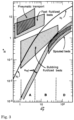
- fluidized bed regimes that can be encountered with increasing superficial velocity (u) of a fluid in a reactor.
- fluidized bed conditions are achieved when the superficial velocity of a fluid is above the minimum fluidization velocity u mf .
- fluidized bed regimes that can be encountered with increasing superficial velocity include: smooth fluidized bed, bubbling fluidized bed, and above the terminal velocity ut: slugging and/or fast fluidized bed.
- slugging and fast fluidized bed regimes there is an increasing degree of entrainment of catalyst particles in the fluid flow.
- such entrainment of particles in the fluid flow is prevented as much as possible.
- Fast fluidized bed conditions are for instance typically applied in modern fluid catalytic cracking (FCC) processes, but are less suitable for the aromatization step of the present invention.
- FCC fluid catalytic cracking
- smooth or bubbling fluidized bed conditions refers to conditions where the superficial velocity of the fluid is equal to or above the minimum fluidization velocity u mf , and below the terminal velocity u t above which significant entrainment of catalyst particles may occur.
- Empirical measurements can be performed on the catalyst bed in order to assess under which fluidization regime the reaction operates or to which extent entrainment of catalyst particles occurs, for instance by placing a gamma radiation source on one side of the reactor and measuring the intensity of the transmitted radiation on the other side on different heights along the reactor.
- the weight hourly space velocity is in the range of 0.1-10.0 h -1 , preferably 0.5-2.0 h -1 , more preferably 0.7-1.5 h -1 .
- the weight hourly space velocity is defined as the mass of pyrolysis vapor (in kg per hour) that is led over a mass of aromatization catalyst present in the aromatization reactor (in kg).
- the mass of aromatization catalyst refers to the mass of entire mass of catalyst particles present in the aromatization reactor.
- the mass of the catalyst for calculating the WHSV refers to the mass of the entire catalyst particles, and not the mass of the active domains only.
- the gas flow of the pyrolysis vapors entering the smooth or bubbling fluidized bed reactor is 200 to 10 000 kg/h, preferably 400 to 7 000 kg/h.
- the amount of catalyst particles present in the aromatization reactor is 200 to 10 000 kg, preferably 400 to 7 000 kg.
- the aromatization is performed in a substantially cylindrical vessel, meaning that the horizontal cross-section of the vessel is substantially circular.
- the aromatization may also be performed in a cuboid vessel, meaning that the horizontal cross-section of the vessel is substantially square, for instance in case the vessel is made of refractory material.
- the vessel has a diameter of 0.5-4.0 m, more preferably 1.0-2.0 m.
- the height of the vessel in which aromatization is performed should be enough to accommodate the smooth or bubbling fluidized catalyst bed.
- the height of the catalyst bed can be in the order of magnitude of 2.0 m. Therefore, the height of the vessel is preferably 5.0 m or more, such as 5.0-15 m, or 6.0-10 m.
- the aromatization catalyst is present in the aromatization reactor in the form of a plurality of solid catalyst particles.
- the catalyst particles preferably have an average particles size of 1-150 ⁇ m, preferably, 20-120 ⁇ m, such as 30-100 ⁇ m.
- the bulk density of the catalyst particles may be 1400 kg/m 3 or less, preferably in the range of 500-1300 kg/m 3 , more preferably in the range of 700-1000 kg/m 3 .
- Catalyst particles that may be particularly suitable as aromatization catalyst, and/or which may be especially suitable for fluidization are commercial FCC catalyst particles, for instance obtained from Albemarle Catalysts Company B.V.
- the superficial velocity of the pyrolysis vapors entering the aromatization reactor is 0.005 m/s or more, preferably 0.01 to 1.0 m/s, more preferably 0.02 to 0.8 m/s.
- step c) of contacting the pyrolysis vapors with an aromatization catalyst at an aromatization temperature in a catalytic conversion step to yield a conversion product further yields carbonaceous deposits on the aromatization catalyst
- step c) may further comprise the steps of: c1) extracting a fraction of the aromatization catalyst comprising carbonaceous deposits from the aromatization reactor thereby creating a catalyst circulation stream; c2) separating entrained fluid from the aromatization catalyst comprising carbonaceous deposits of the catalyst circulation stream, preferably using a stripper; c3) regenerating the aromatization catalyst in a regenerator, wherein the regenerator is preferably also a smooth or bubbling fluidized bed reactor; c4) feeding regenerated aromatization catalyst to the aromatization reactor; thereby obtaining circulation of aromatization catalyst.
- Separating entrained fluid, such as fluid reactants, BTX, and/or other fluid products from the catalyst may be performed via stripping, for instance using nitrogen gas and/or steam.
- Regeneration of the aromatization catalyst is preferably performed in the presence of oxygen, for instance by using air.
- regeneration is performed at a regeneration temperature (T reg ) of 500 °C or higher, preferably 600 °C or higher, more preferably 650 °C or higher.
- T reg regeneration temperature
- the aromatization catalyst may get damaged. Therefore, preferably, regeneration of the aromatization catalyst is performed at temperatures below 900 °C, such as 700-800 °C.
- the frequency at which the aromatization catalyst should be regenerated may vary.
- the rate of circulation of the catalyst can be controlled independently from the weight hourly space velocity. This is in contrast to fast fluidization conditions (which is comparable to plug flow conditions) in a riser, where the catalyst travels along with the gaseous stream of reactants and products.
- the total amount of aromatization catalyst present in the aromatization reactor is circulated between the aromatization reactor and the regenerator 0.2-20 times per hour, preferably 0.5-15 times per hour, more preferably 1-10 times per hour.
- the regenerator also operates under smooth or bubbling fluidized bed conditions.
- contacting the pyrolysis vapors with an aromatization catalyst in the smooth or bubbling fluidized bed reactor is performed at aromatization temperature (T arom ) in the range of 300 to 650 °C, preferably 400 to 600 °C, more preferably 500 to 575 °C, such as 540 to 560 °C.
- T arom aromatization temperature
- product gases may be separated from the catalyst particles, e.g. using a cyclone train that may for instance be placed outside the aromatization reactor or in the freeboard section of the aromatization reactor. Because of the smooth or bubbling fluidized bed conditions, the amount of entrained particles in the fluid product stream is typically low because the superficial velocity is far below the terminal velocity of most of the catalyst bed particles.
- the gauge pressure upstream the aromatization reactor is preferably 0.2 to 2.5 bar, more preferably 0.5 to 2.0 bar, such as 0.5-1.5 bar.
- the fluidized catalyst bed will present resistance to the fluid flow, which may lead to a pressure drop over the aromatization reactor.
- This pressure drop may for instance be in the range of 0.05-1.5 bar, such as 0.10-1.0 bar.
- the pyrolysis treatment may for instance be performed at a pyrolysis temperature (T pyr ) in the range of 400 to 700 °C, preferably 400 to 600 °C.
- T pyr pyrolysis temperature
- the aromatization reactor may be fed with the pyrolysis vapors via a gas distributor system, e.g. a plate or tubes with tuyeres or a ringed sparger.
- a gas distributor system e.g. a plate or tubes with tuyeres or a ringed sparger.
- the average residence time of fluid in the smooth or bubbling fluidized bed present in the aromatization reactor is less than 2 minutes, preferably less than 1 minute, more preferably less than 30 seconds.
- the average residence time of fluid in the smooth or bubbling fluidized bed will be 0.5 second or more, for instance 1.0-60 seconds, or 2.0-45 seconds.
- the aromatization catalyst may comprise one or more of a zeolite catalyst, a non-zeolite catalyst, a metal catalyst and/or a metal oxide catalyst.
- the aromatization catalyst is a zeolite catalyst, suitably selected from aluminosilicates, SAPOs, silicates and combinations thereof. It has been found that the aromatization catalyst preferably is acidic. The acidity may be influenced by the structure of the aluminosilicate and also by the ratio between silicate moieties and aluminate moieties in the aluminosilicate. Suitable silica-alumina ratios include those in the range of 5 to 100, preferably, from 10 to 80, more preferably from 20 to 60.
- the pore diameter of the aromatization catalysts is in the range of 4.5 to 6.5 ⁇ , preferably from 5 to 6 ⁇ .
- the zeolite catalyst is preferably selected from the group consisting of (S)AlPO-31, EU-1, ferrierite, IM-5, MCM-22, mordenite, SSZ-20, SSZ-23, SSZ-55, SUZ-4, TNU-9, zeolite A, zeolite beta, zeolite X, zeolite Y, ZSM-11, ZSM-23, ZSM-35, ZSM-5, ZSM-57 and combinations thereof and can also be treated, exchanged, or impregnated with metals in order to improve the yield of aromatics.
- the zeolite catalyst is ZSM-5.
- Metals could be chosen from nickel, platinum, vanadium, palladium, manganese, cobalt, zinc, copper, chromium, gallium, sodium, bismuth, tungsten, zirconium, indium, tin, thallium, lead, molybdenum, and/or any of their oxides, among others.
- the aromatization catalyst may further comprise an amorphous binder.
- the catalyst may suitably comprise an amorphous binder in addition to a zeolite.
- the amorphous binder gives the particle thus obtained strength, density, shape, and provides a certain particle size to the catalyst particles. Therefore, the amorphous binder can suitably be selected from inorganic refractory oxides, in particular alumina, silica, silica-alumina, titania, zirconia, clays, layered mixed-metal oxides, phosphates, sulphonates and mixtures thereof.
- the amount of the binder in such combinations may vary within wide ranges.
- the amount of amorphous binder in a zeolitic second catalyst is in the range of 30 to 80 wt.%, preferably, 40 to 70 wt.%, based on the weight of the zeolite and the amorphous binder.
- Such a ratio not only provides a particle with a satisfactory mechanical strength, but is also, in the case of silica-alumina, provide the synergistic effect of an increased aromatic compound yield, compared to the proportionally expected yield.
- the aromatization catalyst may be regenerated by contacting the catalyst with carbonaceous deposits with oxygen to yield a regenerated aromatization catalyst.
- FIG 1 a schematic overview of part of a process according to the invention is shown.
- Pyrolysis vapors (61) enter at the bottom of aromatization reactor (20).
- Product vapors with entrained solid particles, such as catalyst particles and/or coke (62) are led to cyclone (21), in which catalyst particles and other solids are separated from the product vapor stream, and fed back (51) into aromatization reactor (20).
- Product vapors (63) are led out of cyclone (21).
- catalyst circulation stream (55) is extracted from the fluidized catalyst bed.
- the catalyst particles in the catalyst circulation stream (55) will typically comprise catalyst particles containing different amounts of carbonaceous deposits.
- stripper (22) recoverable fluids including products such as BTX are stripped from the catalyst particles using stripper gas (71), and a stream containing stripper gas and recoverable fluids (64) exits the top of stripper (22).
- Catalyst circulation stream without fluids (56) is led to regenerator (23) in which carbonaceous deposits are burned from the catalyst particles using regeneration gas (72), e.g. air.
- Combustion gases with entrained catalyst particles (73) are led to cyclone (26), which is used to separate entrained catalyst particles from the combustion gases.
- Entrained catalyst particles (52) are led back to the regenerator and combustion gases (74), which typically comprises regeneration gas enriched with combustion products such as CO and/or CO 2 , exit cyclone (26).
- Regenerated catalyst circulation stream (57) is led to riser (24) where riser gas (75) is used to transport the regenerated catalyst particles to cyclone (25).
- this stream is separated again in regenerated catalyst particles (53) and riser gas (76), and regenerated catalyst particles (53) are led back to aromatization reactor (20).
- thermo-catalytic pyrolysis process for the preparation of low molecular weight monocyclic aromatic compounds according to the invention was performed using mixed plastic waste (DKR350) and crude glycerol as feed, respectively.
- Example 1-1 Mixed plastic waste (DKR350) as feedstock
- the feedstock, mixed plastic waste according to the DKR350 specification is a mixture of different polymers, such as polyethylene, polypropylene, polyethylene terephthalate, and polystyrene.
- DKR350 may also contain fractions of other polymers, such as polyamides, polycarbonates, and other less prevalent polymers.
- DKR350 contains a fraction of biogenic material, originating from various types of biomass. Analyses have shown that this feedstock can contain up to 10 wt.% oxygen atoms. This oxygen can be present in the biogenic fraction, but also in the polymer fraction (for example the polyethylene terephthalate).
- the mixed plastic waste (DKR350) was subjected to a pyrolysis step in a pyrolysis reactor and a catalytic aromatization step in an aromatization reactor.
- the pyrolysis step was performed in a reactor having an inner diameter of 168 mm, while utilizing silver sand with an average particle size of 225 ⁇ m (Geldart B type) as heat transfer medium.
- the sand loading in the pyrolysis reactor was 10 kg, resulting in a fluidized bed height of approximately 500 mm.
- a feed rate of 5 to 10 kg/h of feedstock towards the pyrolysis reactor was used.
- the heat transfer medium in the pyrolysis reactor was fluidized using nitrogen gas, at 2.5 kg/h, via a gas distribution plate.
- the aromatization step was performed in a fluidized bed aromatization reactor having an inner diameter of 256 mm.
- FCC-like catalyst particles with an average particle size of 70 ⁇ m and a density of approximately 780 kg/m 3 when fluidized (Geldart A type) were used as catalyst.
- the catalyst loading in the catalytic reactor was 10 kg.
- the superficial gas velocity of 0.06 to 0.1 m/s, corresponding to approximately 30 to 60 times the minimum fluidization velocity, meaning that there were bubbling fluidized bed conditions in the aromatization reactor.
- the WHSV was between 0.5 and 1.0 h -1 and the residence time in the catalyst bed was approximately 2 seconds.
- the BTX rich product stream exiting the aromatization reactor was transferred to a condensation section where the condensables were retrieved as a liquid phase product, and the lights (non-condensables, such as methane, hydrogen, carbon monoxide, carbon dioxide, and propane) remained in the gas phase.
- the liquid product was subsequently analyzed.
- the quantification of benzene, toluene, and xylenes was performed on a GC-FID by means of an internal standard method where octane was used as internal standard.
- the weight fraction of oxygenates was also determined. The results are presented in Table 1.
- Example 1-2 Crude glycerol as feedstock
- crude glycerol typically contains some contaminants such as ashes (mainly potassium salts), water, and fatty-acid methyl esters. It can also contain a relatively small fraction of methanol. Analyses have shown that ash levels can be as high as 6 wt%, whereas water levels can be up to 5 wt%. Fatty-acid methyl ester levels can be as high as 10 wt%. Based on the atomic ratios of pure glycerol, the glycerol feedstock contains ca. 52 wt% of oxygen atoms and is therefore rich in oxygen.
- pyrolysis was performed in a liquid-fed pyrolysis reactor, followed by aromatization in a fluidized bed aromatization reactor.
- the aromatization reactor, and the equipment for condensation and analysis of the product stream is the same as described above for the example in which mixed plastic waste was used as feedstock.
- the pyrolysis step was performed in a reactor having an inner diameter of 498 mm in which preheated feedstock was introduced using a spray nozzle. A feedrate of 5 to 10 kg/h of feedstock towards the pyrolysis reactor was used. The pyrolysis reactor was flushed using nitrogen gas, at 2.0 kg/h. The pyrolysis residence time in the pyrolysis reactor was in the order of seconds. The pyrolysis was performed at a pyrolysis temperature (T pyr ) between 450 and 500 °C as measured using a thermocouple located directly in the pyrolysis reactor. Gauge pressure inside the pyrolysis reactor was between 100 and 500 mbar.
- Aromatization was performed in the same reactor as used for the process in which mixed plastic waste was the feedstock.
- the catalyst loading was 15 kg.
- the resulting WHSV was 0.5 to 1.0 h -1 and the residence time in the catalyst bed was approximately 1 to 2 seconds.
- the catalyst was also the same as the one used in the mixed plastic waste process.
- the aromatization temperature (T arom ) was 550 °C, as measured by a thermocouple located directly inside the catalyst bed, and the gauge pressure inside the catalytic reactor was between 20 and 300 mbar.
Landscapes
- Chemical & Material Sciences (AREA)
- Engineering & Computer Science (AREA)
- Oil, Petroleum & Natural Gas (AREA)
- Organic Chemistry (AREA)
- Wood Science & Technology (AREA)
- Chemical Kinetics & Catalysis (AREA)
- General Chemical & Material Sciences (AREA)
- Life Sciences & Earth Sciences (AREA)
- Materials Engineering (AREA)
- Dispersion Chemistry (AREA)
- Combustion & Propulsion (AREA)
- Organic Low-Molecular-Weight Compounds And Preparation Thereof (AREA)
- Low-Molecular Organic Synthesis Reactions Using Catalysts (AREA)
- Production Of Liquid Hydrocarbon Mixture For Refining Petroleum (AREA)
Priority Applications (7)
| Application Number | Priority Date | Filing Date | Title |
|---|---|---|---|
| EP23182179.4A EP4484523A1 (de) | 2023-06-28 | 2023-06-28 | Katalytische aromatisierung von pyrolysedämpfen |
| PCT/NL2024/050348 WO2025005802A1 (en) | 2023-06-28 | 2024-06-28 | Catalytic aromatization of pyrolysis vapors |
| EP24738405.0A EP4735558A1 (de) | 2023-06-28 | 2024-06-28 | Katalytische aromatisierung von pyrolysedämpfen |
| KR1020267002783A KR20260028844A (ko) | 2023-06-28 | 2024-06-28 | 열분해 증기의 촉매적 방향족화 |
| AU2024305731A AU2024305731A1 (en) | 2023-06-28 | 2024-06-28 | Catalytic aromatization of pyrolysis vapors |
| CN202480043005.4A CN121488021A (zh) | 2023-06-28 | 2024-06-28 | 热解蒸汽的催化芳构化 |
| IL325605A IL325605A (en) | 2023-06-28 | 2025-12-24 | Catalytic aromatization of pyrolysis vapors |
Applications Claiming Priority (1)
| Application Number | Priority Date | Filing Date | Title |
|---|---|---|---|
| EP23182179.4A EP4484523A1 (de) | 2023-06-28 | 2023-06-28 | Katalytische aromatisierung von pyrolysedämpfen |
Publications (1)
| Publication Number | Publication Date |
|---|---|
| EP4484523A1 true EP4484523A1 (de) | 2025-01-01 |
Family
ID=87036066
Family Applications (2)
| Application Number | Title | Priority Date | Filing Date |
|---|---|---|---|
| EP23182179.4A Withdrawn EP4484523A1 (de) | 2023-06-28 | 2023-06-28 | Katalytische aromatisierung von pyrolysedämpfen |
| EP24738405.0A Pending EP4735558A1 (de) | 2023-06-28 | 2024-06-28 | Katalytische aromatisierung von pyrolysedämpfen |
Family Applications After (1)
| Application Number | Title | Priority Date | Filing Date |
|---|---|---|---|
| EP24738405.0A Pending EP4735558A1 (de) | 2023-06-28 | 2024-06-28 | Katalytische aromatisierung von pyrolysedämpfen |
Country Status (6)
| Country | Link |
|---|---|
| EP (2) | EP4484523A1 (de) |
| KR (1) | KR20260028844A (de) |
| CN (1) | CN121488021A (de) |
| AU (1) | AU2024305731A1 (de) |
| IL (1) | IL325605A (de) |
| WO (1) | WO2025005802A1 (de) |
Cited By (1)
| Publication number | Priority date | Publication date | Assignee | Title |
|---|---|---|---|---|
| CN120136657A (zh) * | 2025-03-13 | 2025-06-13 | 广东工业大学 | 一种废聚烯烃塑料催化热解制轻质芳烃的方法 |
Citations (1)
| Publication number | Priority date | Publication date | Assignee | Title |
|---|---|---|---|---|
| WO2020204707A1 (en) | 2019-03-29 | 2020-10-08 | Biobtx B.V. | Process for the preparation of low molecular weight aromatic compounds such as benzene, toluene, and xylenes (btx) from plastics |
-
2023
- 2023-06-28 EP EP23182179.4A patent/EP4484523A1/de not_active Withdrawn
-
2024
- 2024-06-28 EP EP24738405.0A patent/EP4735558A1/de active Pending
- 2024-06-28 KR KR1020267002783A patent/KR20260028844A/ko active Pending
- 2024-06-28 WO PCT/NL2024/050348 patent/WO2025005802A1/en not_active Ceased
- 2024-06-28 AU AU2024305731A patent/AU2024305731A1/en active Pending
- 2024-06-28 CN CN202480043005.4A patent/CN121488021A/zh active Pending
-
2025
- 2025-12-24 IL IL325605A patent/IL325605A/en unknown
Patent Citations (1)
| Publication number | Priority date | Publication date | Assignee | Title |
|---|---|---|---|---|
| WO2020204707A1 (en) | 2019-03-29 | 2020-10-08 | Biobtx B.V. | Process for the preparation of low molecular weight aromatic compounds such as benzene, toluene, and xylenes (btx) from plastics |
Non-Patent Citations (3)
| Title |
|---|
| JARVIS ET AL., ENERGY FUELS, vol. 32, 2018, pages 1733 |
| JARVIS MARK W. ET AL: "Catalytic Upgrading of Biomass Pyrolysis Oxygenates with Vacuum Gas Oil Using a Davison Circulating Riser Reactor", ENERGY & FUELS, vol. 32, no. 2, 15 February 2018 (2018-02-15), WASHINGTON, DC, US., pages 1733 - 1743, XP093099557, ISSN: 0887-0624, Retrieved from the Internet <URL:http://pubs.acs.org/doi/pdf/10.1021/acs.energyfuels.7b02337> DOI: 10.1021/acs.energyfuels.7b02337 * |
| WERTHER ET AL: "Fluidized-Bed Reactors", 30 November 2011, ULLMANN'S ENCYCLOPEDIA OF INDUSTRIAL CHEMISTRY, 7TH EDITION, WILEY-VCH, WEINHEIM, GERMANY, PAGE(S) 322 - 327, ISBN: 978-3-527-32943-4, XP009546190 * |
Cited By (1)
| Publication number | Priority date | Publication date | Assignee | Title |
|---|---|---|---|---|
| CN120136657A (zh) * | 2025-03-13 | 2025-06-13 | 广东工业大学 | 一种废聚烯烃塑料催化热解制轻质芳烃的方法 |
Also Published As
| Publication number | Publication date |
|---|---|
| IL325605A (en) | 2026-02-01 |
| WO2025005802A1 (en) | 2025-01-02 |
| AU2024305731A1 (en) | 2026-01-22 |
| EP4735558A1 (de) | 2026-05-06 |
| CN121488021A (zh) | 2026-02-06 |
| KR20260028844A (ko) | 2026-03-04 |
Similar Documents
| Publication | Publication Date | Title |
|---|---|---|
| US4071573A (en) | Prolonging zeolite catalyst life in methanol conversion to gasoline by disposing of exothermic reaction heat | |
| US8269056B2 (en) | Process for the preparation of an olefinic product | |
| US4423274A (en) | Method for converting alcohols to hydrocarbons | |
| KR100651418B1 (ko) | 고속유동층을 이용하여 탄화수소 원료로부터 경질 올레핀을제조하는 접촉분해 공정 | |
| EP2303805B1 (de) | Verfahren zur herstellung von olefinen aus sauerstoffhaltigen organischen verbindungen | |
| EP2303806B1 (de) | Verfahren zur herstellung von olefinen aus sauerstoffhaltigen organischen verbindungen | |
| CN107961743B (zh) | 一种由含氧化合物制备丙烯、c4烃类的快速流化床反应器、装置及方法 | |
| CN108350367B (zh) | 流化催化裂化的方法和系统 | |
| JP2022528272A (ja) | プラスチックからベンゼン、トルエン、キシレン(btx)などの低分子量芳香族化合物を製造する方法 | |
| EP2300396B1 (de) | Verfahren zur herstellung von olefinen aus sauerstoffhaltigen organischen verbindungen | |
| JPS6338392B2 (de) | ||
| EP2303807B1 (de) | Verfahren zur herstellung von olefinen aus sauerstoffhaltigen organischen verbindungen | |
| US6045690A (en) | Process for fluid catalytic cracking of heavy fraction oils | |
| US20230183582A1 (en) | Process for converting solid hydrocarbonaceous materials to chemicals and fuels | |
| KR102901024B1 (ko) | 반대 흐름 촉매 분해 반응기에서 탄화수소를 처리하여 경질 올레핀을 제조하는 방법 | |
| US4541923A (en) | Catalyst treatment and flow conditioning in an FCC reactor riser | |
| CN107963957B (zh) | 一种制备丙烯和c4烃类的方法及其装置 | |
| CN104672040A (zh) | 一种含氧化合物制低碳烯烃的方法及其使用的设备 | |
| JP6864957B2 (ja) | プロピレン及びc4の炭化水素類を製造する方法及びその装置 | |
| CN100577614C (zh) | 用于催化转化含氧物并再生和汽提催化剂的方法和系统 | |
| US8022002B2 (en) | Integrated regeneration of non-noble metal catalysts | |
| WO2025005802A1 (en) | Catalytic aromatization of pyrolysis vapors | |
| US11707720B2 (en) | Integrated loop systems for catalyst regeneration in multi-zone fluidized bed reactors and methods of using the same | |
| EP0490453A1 (de) | Verfahren und Apparat zur Beseitigung von Kohlenstoffmaterialien von Feststoffteilchen | |
| JPH03207795A (ja) | 統合されたパラフィン改善方法及び接触分解方法 |
Legal Events
| Date | Code | Title | Description |
|---|---|---|---|
| PUAI | Public reference made under article 153(3) epc to a published international application that has entered the european phase |
Free format text: ORIGINAL CODE: 0009012 |
|
| STAA | Information on the status of an ep patent application or granted ep patent |
Free format text: STATUS: THE APPLICATION HAS BEEN PUBLISHED |
|
| AK | Designated contracting states |
Kind code of ref document: A1 Designated state(s): AL AT BE BG CH CY CZ DE DK EE ES FI FR GB GR HR HU IE IS IT LI LT LU LV MC ME MK MT NL NO PL PT RO RS SE SI SK SM TR |
|
| STAA | Information on the status of an ep patent application or granted ep patent |
Free format text: STATUS: THE APPLICATION IS DEEMED TO BE WITHDRAWN |
|
| 18D | Application deemed to be withdrawn |
Effective date: 20250702 |