EP4484663A1 - Verfahren zur herstellung eines ankerkanals - Google Patents
Verfahren zur herstellung eines ankerkanals Download PDFInfo
- Publication number
- EP4484663A1 EP4484663A1 EP23181686.9A EP23181686A EP4484663A1 EP 4484663 A1 EP4484663 A1 EP 4484663A1 EP 23181686 A EP23181686 A EP 23181686A EP 4484663 A1 EP4484663 A1 EP 4484663A1
- Authority
- EP
- European Patent Office
- Prior art keywords
- anchor
- shaft
- rivet
- flange
- channel
- Prior art date
- Legal status (The legal status is an assumption and is not a legal conclusion. Google has not performed a legal analysis and makes no representation as to the accuracy of the status listed.)
- Withdrawn
Links
Images
Classifications
-
- E—FIXED CONSTRUCTIONS
- E04—BUILDING
- E04B—GENERAL BUILDING CONSTRUCTIONS; WALLS, e.g. PARTITIONS; ROOFS; FLOORS; CEILINGS; INSULATION OR OTHER PROTECTION OF BUILDINGS
- E04B1/00—Constructions in general; Structures which are not restricted either to walls, e.g. partitions, or floors or ceilings or roofs
- E04B1/38—Connections for building structures in general
- E04B1/41—Connecting devices specially adapted for embedding in concrete or masonry
- E04B1/4107—Longitudinal elements having an open profile, with the opening parallel to the concrete or masonry surface, i.e. anchoring rails
Definitions
- the invention relates to a method for manufacturing an anchor channel according to the preamble of claim 1, and to an anchor channel obtained using this method.
- US4052833 A discloses a method for manufacturing an anchor channel, in which a flanged monolithic anchor body is inserted into a channel body and connected thereto by riveting.
- EP0400588 A1 discloses another method for manufacturing an anchor channel.
- a multi-part, non-monolithic anchor body is used.
- the non-monolithic anchor body comprises a shank consisting of constructional steel, which shank is welded to a foot consisting of stainless steel.
- the foot is, in term, riveted to the channel body.
- the foot is oversized with respect to the shank, so that a ridge, which forms during the welding-together of shank and foot, does not radially project over the adjacent foot.
- an anchor channel comprising:
- the invention is based on the finding that it might be desirable to have shop heads of particularly large diameter at the rivet connection site between the monolithic anchor body and the channel body. This is since having large diameter shop heads allows large area force transfer, and thus allows reducing the wall strength of the channel body without compromising on the strength of the rivet connection. On the other hand, since the additional mass of a large diameter shop head is merely local, the overall material expenditure can be kept particularly low.
- the material for forming large diameter shop heads generally originates from the deformed rivet shaft. In this context, the invention has found that it can be advantageous to provide this shop head forming material in the cross-section of the rivet shaft, instead of in the length of the rivet shaft.
- the invention proposes to provide, at least adjacent to the flange, the rivet shaft with larger cross-sectional area than the anchor shaft (with cross-sectional area in both cases measured orthogonally to the longitudinal axis of the monolithic anchor body).
- the relatively large cross-section of the rivet shaft allows particularly low riveting effort, whereas the relatively thin anchor shaft prevents unnecessarily high material expenditure.
- particularly good anchor performance can be achieved at particularly low expenditure, with regards to channel body wall thickness, overall anchor body mass and/or manufacturing effort.
- An anchor channel can comprise a generally C-shaped channel body, and at least one anchor body, preferably a plurality of anchor bodies, protruding therefrom. If a plurality of anchor bodies is provided, it is particularly preferred that all of them are attached to the channel body by means of the described method.
- the channel body and/or the monolithic anchor body consist preferably of metal, in particular steel, which might also be coated.
- the flange is arranged axially (with respect to the anchor body's longitudinal axis) between the rivet shaft and the anchor shaft.
- the flange is intended to abut against the channel bottom in a region surrounding the rivet hole, thereby preventing the monolithic anchor body from being pushed too deeply into the channel body.
- the flange can have any shape suitably for this purpose, e.g. a circular disc shape, a tapering shape, in particular a conical shape, or also others.
- the flange can have a ring shoulder facing the rivet shaft and intended to abut against the channel bottom and/or the flange can have a taper facing the anchor shaft.
- the cross-sectional area of the monolithic anchor body, in particular of its rivet shaft and/or of its anchor shaft, can in particularly be measured perpendicularly to the anchor body's longitudinal axis and/or to an anchor body insertion direction, i.e. to a direction in which the rivet shaft of the monolithic anchor body is inserted into the rivet hole.
- the monolithic anchor body is monolithic, i.e. it is formed from a single piece of material without joints or seams.
- the monolithic anchor body can be obtained by a rolling process applied to a piece of wire.
- the rivet shaft has a free end. This free end might be provided with a tapered tip, e.g. for facilitating insertion into the rivet hole.
- the rivet shaft is inserted into the rivet hole with the free end first.
- the rivet shaft is inserted into the rivet hole from outside of the channel body, so that the rivet shaft then projects into the inside of the anchor channel.
- the shop head is a local widening of the rivet shaft, that is wide enough to prevent withdrawal of the rivet shaft out of the rivet hole.
- the shop head is formed at the free end of the rivet shaft.
- the monolithic anchor body when the monolithic anchor body is provided, the monolithic anchor body further comprises an anchor head that is arranged on the anchor shaft, in particularl at an end of the anchor shaft that is remote from the flange. Accordingly, an anchor head, i.e. a widening for anchoring, is provided on the monolithic anchor body from the beginning of the manufacturing sequence. This can provide particularly good anchoring performance at particularly low manufacturing effort.
- the anchor head is a monolithic part of the monolithic anchor body and can, for example, be formed in a rolling process applied to the above-mentioned piece of wire.
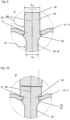
- the rivet shaft has, at least in the rivet shaft region located adjacent to the flange, generally circular cross-section with diameter d 33
- the anchor shaft has, at least in the anchor shaft region located adjacent to the flange, generally circular cross-section with diameter d 22 .
- the respective diameter extends preferably perpendicular to the anchor body's longitudinal axis and/or to the anchor body insertion direction.
- the rivet shaft or the anchor shaft, respectively are generally circularly cylindrical in said regions. This can allow particularly easy manufacturing, e.g. by rolling, and particularly good force absorption.
- d 33 > d 22 + 0.3 mm
- d 33 ⁇ d 22 + 2.0 mm .
- the invention also relates to an anchor channel obtained by the described method.
- Features that are described here in connection with the method for manufacturing the anchor channel can also be used in connection with the anchor channel obtained with the method.
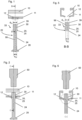
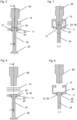
- the figures illustrate a method for manufacturing an anchor channel and an anchor channel obtained by means of this method.
- a generally C-shaped channel body 10 and a monolithic anchor body 20 are provided as independent members.
- the channel body 10 includes a channel bottom 11 and at least one rivet hole 12 in the channel bottom 11.
- the channel body 10 can consist of metal, more preferably of steel, that can also be coated.
- the monolithic anchor body 20 extends along an anchor body's longitudinal axis 99.
- the monolithic anchor body 20 comprises a flange 25, a rivet shaft 30 that projects from the flange 25 and an anchor shaft 24 that projects from the flange 25.
- the anchor shaft 24 and the rivet shaft 30, respectively, project from opposite sides of the flange 25, i.e. the flange 25 is located axially between the anchor shaft 24 and the rivet shaft 30.
- the monolithic anchor body 20 further comprises an anchor head 26 that is attached to the anchor shaft 24.
- the anchor head 26 and the flange 25, respectively, are arranged on the anchor shaft 24 at opposite ends of the anchor shaft 24.
- the monolithic anchor body 20 is monolithic, i.e. the anchor shaft 24, the rivet shaft 30, the flange 25 and, if present also the anchor head 26 are a single piece.
- the monolithic anchor body 20 consists of metal, preferably of steel, that can also be coated.
- Both the anchor shaft 24 and the rivet shaft 30 are generally circular cylindrical.
- the rivet shaft 30 also comprises a tapering tip 39 at the free end of the rivet shaft 30, in order to facilitate insertion of the rivet shaft into the rivet hole 12.
- the generally circular cylindrical rivet shaft 30 has generally constant diameter d 33 in a rivet shaft region 33 that is located adjacent to the flange 25, wherein said rivet shaft region 33 with generally constant diameter d 33 extends from the flange 25 to the tapering tip 39.
- the generally circular cylindrical anchor shaft 24 has generally constant diameter d 22 in an anchor shaft region 22 that is located adjacent to the flange 25, wherein said anchor shaft region 22 with generally constant diameter d 22 extends from the flange 25 to the anchor head 26. It is provided that d 33 is greater than d 22 .
- the rivet shaft 30 has, at least in said rivet shaft region 33 located adjacent to the flange 25, larger cross-sectional area that has the anchor shaft 24, at least in said anchor shaft region 22 located adjacent to the flange 25, wherein cross-sectional area is measure in both cases orthogonally to the monolithic anchor body's longitudinal axis 99.
- the flange 25 provides a ring shoulder, namely where the flange 25 adjoins the rivet shaft region 33 that is located adjacent to the flange 25. Where the flange 25 adjoins the anchor shaft region 22 that is located adjacent to the flange 25, the flange 25 is, in the shown embodiment, provided with a conical taper, but this is an example only.
- the monolithic anchor body 20 is inserted, with free end of the rivet shaft 30 first, into the rivet hole 12 in the channel bottom 11, preferably until the flange 25 (in particular with its ring shoulder) abuts against the channel bottom 11.
- the rivet shaft 30 then extends through the rivet hole 12 into the channel body 10, with the anchor shaft 24 projecting from the channel body 10 on the outside of the channel body 10.
- the resulting configuration is shown in figures 2, 6 and 9 .
- the rivet shaft 30 is subsequently upset at the free end of the rivet shaft 30 that is located within the channel body 10, wherein upsetting is preferably performed by means of an orbital riveting process using an orbital riveting die 60.
- upsetting is preferably performed by means of an orbital riveting process using an orbital riveting die 60.
- a broadened shop head 35 is formed at the free end of the rivet shaft 30, which locks the rivet shaft 30 on the channel bottom 11 against being pulled out of the rivet hole 12.
- the upsetting process rivets the monolithic anchor body 20 to the channel body 10.
- the upsetting step is illustrated in figures 3, 7 and 10
- the final state, in which the monolithic anchor body 20 is riveted to the channel body 10, is shown in figures 4 and 8 .
Landscapes
- Engineering & Computer Science (AREA)
- Architecture (AREA)
- Physics & Mathematics (AREA)
- Electromagnetism (AREA)
- Civil Engineering (AREA)
- Structural Engineering (AREA)
- Insertion Pins And Rivets (AREA)
Priority Applications (4)
| Application Number | Priority Date | Filing Date | Title |
|---|---|---|---|
| EP23181686.9A EP4484663A1 (de) | 2023-06-27 | 2023-06-27 | Verfahren zur herstellung eines ankerkanals |
| PCT/EP2024/066045 WO2025002784A1 (en) | 2023-06-27 | 2024-06-11 | Method for manufacturing an anchor channel |
| CN202480043137.7A CN121443813A (zh) | 2023-06-27 | 2024-06-11 | 用于制造锚固通道的方法 |
| EP24732469.2A EP4735700A1 (de) | 2023-06-27 | 2024-06-11 | Verfahren zur herstellung eines ankerkanals |
Applications Claiming Priority (1)
| Application Number | Priority Date | Filing Date | Title |
|---|---|---|---|
| EP23181686.9A EP4484663A1 (de) | 2023-06-27 | 2023-06-27 | Verfahren zur herstellung eines ankerkanals |
Publications (1)
| Publication Number | Publication Date |
|---|---|
| EP4484663A1 true EP4484663A1 (de) | 2025-01-01 |
Family
ID=87036058
Family Applications (2)
| Application Number | Title | Priority Date | Filing Date |
|---|---|---|---|
| EP23181686.9A Withdrawn EP4484663A1 (de) | 2023-06-27 | 2023-06-27 | Verfahren zur herstellung eines ankerkanals |
| EP24732469.2A Pending EP4735700A1 (de) | 2023-06-27 | 2024-06-11 | Verfahren zur herstellung eines ankerkanals |
Family Applications After (1)
| Application Number | Title | Priority Date | Filing Date |
|---|---|---|---|
| EP24732469.2A Pending EP4735700A1 (de) | 2023-06-27 | 2024-06-11 | Verfahren zur herstellung eines ankerkanals |
Country Status (3)
| Country | Link |
|---|---|
| EP (2) | EP4484663A1 (de) |
| CN (1) | CN121443813A (de) |
| WO (1) | WO2025002784A1 (de) |
Citations (3)
| Publication number | Priority date | Publication date | Assignee | Title |
|---|---|---|---|---|
| US4052833A (en) | 1976-07-13 | 1977-10-11 | Karlheinz Beine | Track assembly with anchoring device |
| EP0400588A1 (de) | 1989-05-31 | 1990-12-05 | Deutsche Kahneisen Gesellschaft West Gmbh | Stauchanker |
| US5729951A (en) * | 1995-07-26 | 1998-03-24 | Halfen Gmbh & Co. Kommanditgesellschaft | Anchoring device for the construction industry |
-
2023
- 2023-06-27 EP EP23181686.9A patent/EP4484663A1/de not_active Withdrawn
-
2024
- 2024-06-11 CN CN202480043137.7A patent/CN121443813A/zh active Pending
- 2024-06-11 EP EP24732469.2A patent/EP4735700A1/de active Pending
- 2024-06-11 WO PCT/EP2024/066045 patent/WO2025002784A1/en not_active Ceased
Patent Citations (3)
| Publication number | Priority date | Publication date | Assignee | Title |
|---|---|---|---|---|
| US4052833A (en) | 1976-07-13 | 1977-10-11 | Karlheinz Beine | Track assembly with anchoring device |
| EP0400588A1 (de) | 1989-05-31 | 1990-12-05 | Deutsche Kahneisen Gesellschaft West Gmbh | Stauchanker |
| US5729951A (en) * | 1995-07-26 | 1998-03-24 | Halfen Gmbh & Co. Kommanditgesellschaft | Anchoring device for the construction industry |
Also Published As
| Publication number | Publication date |
|---|---|
| WO2025002784A1 (en) | 2025-01-02 |
| EP4735700A1 (de) | 2026-05-06 |
| CN121443813A (zh) | 2026-01-30 |
Similar Documents
| Publication | Publication Date | Title |
|---|---|---|
| US6988862B1 (en) | Rivet, riveted joint structure riveting apparatus, and riveting method | |
| EP2490838B1 (de) | Klammerstifthalterung | |
| KR101474477B1 (ko) | 펀치리벳 및 다이 | |
| US3438301A (en) | Hollow rivet and pull-stem assembly for blind fastening or the like | |
| EP0344005B1 (de) | Blindniet | |
| CN1333175C (zh) | 盲铆钉 | |
| US20120090158A1 (en) | Self-piercing riveting | |
| EP0527581A1 (de) | Hochleistungs-Blindboltzen mit gleicher Greifkraft über einen erweiterten Greifbereich | |
| EP1498617A2 (de) | Dreiteiliger Blindbefestiger | |
| EP0958456B1 (de) | Blindniet und verfahren zu seiner herstellung | |
| WO2000028221A2 (en) | Tapered shank rivet | |
| EP0497455A1 (de) | Selbststopfender Blindniet | |
| US3995406A (en) | Rivet fastener system | |
| EP0328314A2 (de) | Blindniet | |
| JP7451853B2 (ja) | リベット締め接合部を形成する方法 | |
| EP2453142A1 (de) | Blindniet und zugehörige Befestigungsmethode | |
| EP4484663A1 (de) | Verfahren zur herstellung eines ankerkanals | |
| US8348565B2 (en) | Rivet | |
| EP1369600A2 (de) | Spreizniet | |
| GB2124317A (en) | Blind rivet assembly | |
| US10400932B2 (en) | Hydraulic plug | |
| EP4033112A1 (de) | Pressmutter | |
| US20250180055A1 (en) | Self-Piercing Rivet and Methods of Making and Using Same | |
| CN220470421U (zh) | 一种拉铆组件 | |
| GB2332722A (en) | Blind rivet with work hardened groove in shank |
Legal Events
| Date | Code | Title | Description |
|---|---|---|---|
| PUAI | Public reference made under article 153(3) epc to a published international application that has entered the european phase |
Free format text: ORIGINAL CODE: 0009012 |
|
| STAA | Information on the status of an ep patent application or granted ep patent |
Free format text: STATUS: THE APPLICATION HAS BEEN PUBLISHED |
|
| AK | Designated contracting states |
Kind code of ref document: A1 Designated state(s): AL AT BE BG CH CY CZ DE DK EE ES FI FR GB GR HR HU IE IS IT LI LT LU LV MC ME MK MT NL NO PL PT RO RS SE SI SK SM TR |
|
| STAA | Information on the status of an ep patent application or granted ep patent |
Free format text: STATUS: THE APPLICATION IS DEEMED TO BE WITHDRAWN |
|
| 18D | Application deemed to be withdrawn |
Effective date: 20250702 |