EP4484677A1 - Einstückiges verbindungselement für einen zaun, verfahren zur herstellung eines solchen verbindungsstücks und zaun mit mindestens einem solchen verbindungselement - Google Patents
Einstückiges verbindungselement für einen zaun, verfahren zur herstellung eines solchen verbindungsstücks und zaun mit mindestens einem solchen verbindungselement Download PDFInfo
- Publication number
- EP4484677A1 EP4484677A1 EP24184171.7A EP24184171A EP4484677A1 EP 4484677 A1 EP4484677 A1 EP 4484677A1 EP 24184171 A EP24184171 A EP 24184171A EP 4484677 A1 EP4484677 A1 EP 4484677A1
- Authority
- EP
- European Patent Office
- Prior art keywords
- tubular portion
- fence
- connecting piece
- panel
- tube
- Prior art date
- Legal status (The legal status is an assumption and is not a legal conclusion. Google has not performed a legal analysis and makes no representation as to the accuracy of the status listed.)
- Withdrawn
Links
Images





Classifications
-
- E—FIXED CONSTRUCTIONS
- E04—BUILDING
- E04H—BUILDINGS OR LIKE STRUCTURES FOR PARTICULAR PURPOSES; SWIMMING OR SPLASH BATHS OR POOLS; MASTS; FENCING; TENTS OR CANOPIES, IN GENERAL
- E04H17/00—Fencing, e.g. fences, enclosures, corrals
- E04H17/14—Fences constructed of rigid elements, e.g. with additional wire fillings or with posts
- E04H17/16—Fences constructed of rigid elements, e.g. with additional wire fillings or with posts using prefabricated panel-like elements, e.g. wired frames
-
- E—FIXED CONSTRUCTIONS
- E04—BUILDING
- E04H—BUILDINGS OR LIKE STRUCTURES FOR PARTICULAR PURPOSES; SWIMMING OR SPLASH BATHS OR POOLS; MASTS; FENCING; TENTS OR CANOPIES, IN GENERAL
- E04H17/00—Fencing, e.g. fences, enclosures, corrals
- E04H17/14—Fences constructed of rigid elements, e.g. with additional wire fillings or with posts
- E04H17/16—Fences constructed of rigid elements, e.g. with additional wire fillings or with posts using prefabricated panel-like elements, e.g. wired frames
- E04H17/17—Fences constructed of rigid elements, e.g. with additional wire fillings or with posts using prefabricated panel-like elements, e.g. wired frames brackets for the connection between panels and posts
Definitions
- the field of the proposed technique is that of the design and manufacture of fences and more particularly that of the connection of panels to vertical posts of a fence.
- the proposed technique concerns, according to a first aspect, a part for connecting panels to vertical posts of a fence.
- the proposed technique also relates, according to a second aspect, to a method of manufacturing such connecting parts.
- the proposed technique further relates, according to a third aspect, to a fence comprising at least one such connecting part of a panel on a vertical post.
- Fencing installations commonly called fences, are frequently implemented in order to demarcate the edges of plots of land and/or to secure access to them.
- a fence is generally made up of a succession of posts, the lower end of which is secured, directly or indirectly, to the ground, generally in such a way that they extend essentially vertically, and at least one separation element secured between two successive posts.
- a panel means any separation element having at least upper and lower pipes connected to each other by means of bars, plates, photovoltaic cells, etc.
- such fences include crosspieces, each connected on either side to a vertical post, by means of an end cap if necessary, configured on the one hand to support (lower crosspiece) or retain (upper crosspiece) the panels, and on the other hand to contribute to the mechanical strength of the fence.
- the proposed technique relates, according to a first aspect, to a single-piece connecting piece for fencing.
- the connecting piece comprises a first tubular portion of closed cross-section, extending along a longitudinal axis, having a first end, capable of cooperating with a fixing end piece on a vertical post of the fence, and a second end extended by a second tubular portion of open cross-section, capable of cooperating with a peripheral portion of the frame of a panel arranged between two posts of the fence.
- the proposed technique therefore makes it possible to exploit the structural rigidity of the panel, and more particularly of its frame, to ensure the connection of this panel to the vertical posts of the fence.
- the implementation of such single-block connection parts therefore makes it possible to avoid the implementation of crosspieces.
- the second tubular portion has a length of between 40 and 70 cm.
- Such a configuration of the second tubular portion makes it possible in particular to ensure an efficient and secure connection of the panel to the connection part.
- the connecting part comprises means for fixing the frame of the panel provided in the second tubular portion.
- Such fixing means make it possible in particular to simplify the assembly and maintenance of the fence panel.
- the second tubular portion is formed by the extension of two adjacent sides of the first tubular portion.
- Such a shape of the second tubular portion makes it possible to simultaneously ensure engagement of the connecting piece on one side of the panel frame and its edge (lower or upper depending on the position of the connecting piece). This therefore makes it possible to ensure that the panel is held in all directions. This results in effective mechanical retention of the panel in the fence.
- the second tubular portion is formed by the extension of two opposite sides of said first tubular portion.
- Such a shape of the second tubular portion which has two portions facing each other, makes it possible in particular to ensure engagement of the connecting piece on each side of the panel frame. This is particularly used to ensure effective fixing of the panel on the connecting piece, in particular by the use of fixing screws passing through the two opposite portions.
- Such a shape also makes it possible to simplify the assembly of the panel in the fence, in particular by allowing the panel to slide between the second tubular portions of the connecting parts previously mounted on the post.
- the proposed technique relates, according to a third aspect, to a fence having at least one panel and at least one connecting piece as described above for connecting a peripheral portion of the frame of the panel to a vertical post.
- a fence equipped with connecting pieces that comply with the proposed technique is notably lighter than traditional fences. This is particularly advantageous for handling and transporting such a fence.
- the use of such connecting pieces also makes it possible to minimise the size of the fence when disassembled. This is also particularly advantageous for storage and transport.
- the panel substantially parallelepiped in shape, is arranged longitudinally between two vertical posts, and at least two longitudinally aligned angles respectively carry a connecting piece to the associated post.
- the panel has a predetermined length
- the connecting piece has a length corresponding to a value between 20 and 30% of the length of the panel.
- Such a configuration of the second tubular portion makes it possible in particular to ensure an efficient and secure connection of the panel to the connection part.
- orientation and positioning are subsequently used to refer arbitrarily to an installed position of the fence, when the latter is fixed, directly or indirectly, to the ground and extends in a plane substantially perpendicular to the ground, so as to be arranged substantially vertically.
- fences which use crosspieces, each connected on either side to a vertical post, configured on the one hand to support (lower crosspiece) or retain (upper crosspiece) panels, and on the other hand to contribute to the mechanical strength of the fence.
- the inventors identified a new and inventive technique exploiting the structural rigidity of the panel to ensure the connection of the panel to the associated vertical posts.
- the general principle of the proposed technique therefore consists of a single-piece connection piece for a fence comprising a first tubular portion of closed cross-section extended by a second tubular portion of open cross-section and allowing the connection of a panel to a vertical post of the fence.
- the proposed technique also relates to a fence comprising at least one such connecting piece.
- the proposed technique further relates to an inventive method of manufacturing two connecting pieces according to the proposed technique, arranged head to tail.
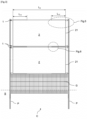
- FIGS. 1 and 2 illustrate an isolated connecting piece and the Figures 3 to 8 illustrate a fence whose panels are coupled to the vertical posts by means of such connecting pieces.
- the single-piece connecting piece 1 comprises a first tubular portion 10, of square cross-section, extending along a longitudinal axis X.
- the first tubular portion 10 has a first end 10 1 capable of cooperating with a tip E for fixing on a vertical post P of a fence C, as illustrated in figures 2 And 7 notably.
- the first tubular portion 10 further has a second end 10 2 , opposite the first end 10 1 , which is partially extended by a second tubular portion 11 capable of cooperating with a peripheral frame portion 21 of a panel 2 arranged between two consecutive posts P of the fence C, as illustrated in figures 3 And 4 notably.
- This second tubular portion 11 which corresponds to the extension of two adjacent sides of the first tubular portion 10, has an open cross section having substantially the shape of an “L”.
- Such a shape of the second tubular portion 11 makes it possible to simultaneously ensure engagement of the connecting piece 1 on one side of the frame 21 of the panel 2 and on the edge (lower or upper depending on the position of the connecting piece) of this same frame, as illustrated in figures 3 And 4 in particular. This therefore ensures that the panel is held in place in all directions.
- the second tubular portion 11 of the connecting piece 1 has a length L 11 predetermined as a function of the length L 2 of the panel 2 of the fence C. More precisely, the length L 11 of the second tubular portion 11 is determined so as to ensure the connection and maintenance of the panel.
- the length L 11 of the second tubular portion 11 corresponds to a value between 20 and 30% of the length L 2 of the fence panel 2, as illustrated in figure 3 notably.
- the second tubular portion 11 further has means 112 for fixing the connecting piece 1 to the frame 21 of the fence panel 2.
- the fence C comprises vertical posts P, spaced from each other and planted in the ground S, between which are positioned, in parts upper and central, two photovoltaic panels 2 and, in the lower part, a rigid grid G made up of a lattice of vertical and horizontal wires.
- Each photovoltaic panel 2 has a complete frame 21 formed of vertical tubes whose common ends are connected by horizontal tubes. The photovoltaic cell(s) are thus bordered by tubes.
- Each panel 2 carries, at its corners, a connecting piece 1 conforming to the proposed technique cooperating with an end piece E. More precisely, each connecting piece 1 is attached to one end of the vertical pipes of the frame 21.
- This end piece E comprises a sleeve, capable of being inserted into the first end 10 1 of the first tubular portion 10, from which a fixing insert projects.
- This fixing insert is configured to cooperate with a fixing clip F1 removably mounted on the post P.
- the fixing clip F1 comprises lugs configured to be inserted into holes P 10 of the post, as illustrated in figure 7 .
- each connecting piece 1 has a length L 11 of 58 cm, i.e. approximately 21% of the length L 2 of the panel 2.
- the length L11 of the second tubular portion 11 can be between 40 and 70 cm, preferably between 50 and 60 cm, for example.
- the fixing means 112 of the connecting part 1 are formed by a plurality of holes for the passage of fixing screws intended to be inserted into the vertical pipes of the frame 21 of the panel 2.
- the proposed technique also relates, according to another aspect, to a method of manufacturing two identical single-piece connecting parts 1 conforming to this first embodiment.
- FIG 9 is a flowchart of the main steps in manufacturing two connecting parts conforming to the proposed technique.
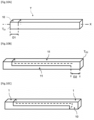
- the Figures 10A to 10C illustrate some of these manufacturing steps.
- the cutting steps can be carried out via a continuous cutting operation, i.e. by alternating transverse and longitudinal cuts, or discontinuous, i.e. by first carrying out the transverse cuts then the longitudinal cuts, or vice versa.
- the manufacturing method further comprises drilling S5 the holes 112 for the passage of fixing means on the second tubular portions 11 of the first and second connecting parts 1.
- Such a drilling step is preferably carried out upstream of the cuts, on the tube therefore, but can also be carried out downstream, on each of the two connection parts 1 in this case.
- FIGS. 11A and 11B illustrate, in schematic perspective and cross-sectional views respectively, a single-piece connecting piece in accordance with a second embodiment of the proposed technique.
- This second embodiment differs from the first embodiment in the pattern of the opening of the open cross-section. For the sake of clarity and conciseness, only the differences from the first embodiment are described hereinafter.
- the second tubular portion 11' of the connecting piece 1' corresponds to the extension of two opposite sides of the first tubular portion 10' of square cross section.
- the second tubular portion 11' thus has a cross-section formed of two straight lines parallel to each other, i.e. substantially in the shape of an "II".
- Figure 11B is a cross-sectional view, according to plane P 11 , of the connecting piece 1' illustrated in Figure 11A .
- the particular shape of the tubular portion 11' is such that it is possible, from a single tube of square section, to shape two connecting pieces 1', arranged head to tail, via a manufacturing process similar to that described in the first embodiment.
- the shape of the second tubular portion 11' which has two facing portions, makes it possible in particular to ensure engagement of the connecting piece 1' on each side of the panel frame. This can be particularly useful for ensuring effective fixing of the panel on the connecting piece 1', in particular by using fixing screws passing through the two opposite portions of the second tubular portion 11'.
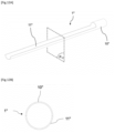
- FIGS. 12A and 12B illustrate, in schematic perspective and cross-sectional views respectively, a single-piece connecting piece in accordance with a third embodiment of the proposed technique.
- This third embodiment is distinguished from the first embodiment by the shape of its cross sections and, by extension, by the pattern of the opening. of the open cross section. For the sake of clarity and conciseness, only the deviations from the first embodiment are described hereinafter.
- the first tubular portion 10" of the connecting piece 1" has an annular cross section.
- the second 11" tubular portion has a semicircular cross-section, i.e. roughly in the shape of a "C".
- Figure 12B is a cross-sectional view, according to plane P 12 , of the connecting piece 1" illustrated in Figure 12A .
- the semi-circular shape of the second tubular portion 11" is such that it is possible, from a single tube of annular section, to shape two connecting pieces 1", arranged head to tail, via a manufacturing process similar to that described in the first embodiment.
- a connecting piece conforming to this third embodiment which presents substantially the same advantages as that of the first embodiment, is particularly interesting for all fences equipped with panels whose frame is formed of annular tubular portions, at least on the connection zones.
- FIGS. 13A and 13B illustrate, in schematic perspective and cross-sectional views respectively, a single-piece connecting piece in accordance with a fourth embodiment of the proposed technique.
- This fourth embodiment is distinguished from the second embodiment by the shape of its cross sections, and by extension, by the pattern of the opening of the open cross section. For the sake of clarity and conciseness, only the divergences from the second embodiment are described hereinafter.
- the first tubular portion 10'" of the connecting piece 1′′′ has an annular cross section.
- the second tubular portion 11′′′ of the connecting piece 1′′′ corresponds to the extension of two quarter circles, also called “sides”, opposite the first tubular portion 10” of annular cross section.
- Figure 13B is a cross-sectional view, according to plane P 13 , of the connecting piece 1′′′ illustrated in Figure 13A .
- tubular portion 11′′′ is such that it is possible, from a single tube of annular section, to shape two connecting pieces 1′′′, arranged head to tail, via a manufacturing process similar to that described in the first embodiment.
- a connecting piece conforming to this fourth embodiment which presents substantially the same advantages as that of the third embodiment, is particularly interesting for all fences equipped with panels whose frame is formed of annular tubular portions, at least on the connection zones.
- the fence comprises two photovoltaic panels.
- the fence can comprise more or fewer photovoltaic panels and/or panels of other types (as long as they have a frame).
- the frame of each panel is formed of vertical tubes whose common ends are connected by horizontal tubes.
- the frame can be partial and therefore formed only of vertical tubes (top and bottom).
- the installation of the fence is carried out by housing the posts directly in the ground.
- the posts are connected to plates which themselves are fixed to concrete blocks or stringers.
- the fixing means are holes for passing fixing screws.
- any other fixing means such as snap-on lugs, can be implemented.
- the fence comprises, in the lower part, a grid.
- a grid In the example illustrated in relation to the first embodiment, the fence comprises, in the lower part, a grid.
- the second tubular portions of the connecting pieces are defined so as to allow, from a single tube, to shape two identical connecting pieces arranged head to tail.
- the full and empty portions of the open cross sections may not be symmetrical. In such cases, any other manufacturing method, less optimized because it does not allow the simultaneous manufacturing of two identical connecting pieces, may be implemented. This may for example be the case when the tube from which the connecting piece is shaped has a rectangular cross section.
- first end of the first tubular portion cooperates with a fixing end piece (intermediate piece).
- this first end is secured directly to the post.
- the first tubular portion of the connecting piece has an oval cross-section.
- Such a shape makes it possible in particular to combine the simplicity of manufacture of the third embodiment and the holding efficiency of the fourth embodiment.
Landscapes
- Engineering & Computer Science (AREA)
- Architecture (AREA)
- Civil Engineering (AREA)
- Structural Engineering (AREA)
- Fencing (AREA)
Applications Claiming Priority (2)
| Application Number | Priority Date | Filing Date | Title |
|---|---|---|---|
| FR2307009A FR3150541A1 (fr) | 2023-06-30 | 2023-06-30 | Piece de raccordement monobloc pour cloture, procede de fabrication d’une telle piece de raccordement et cloture comprenant au moins une telle piece de raccordement |
| FR2308345A FR3150542A1 (fr) | 2023-06-30 | 2023-08-01 | Piece de raccordement monobloc pour cloture, procede de fabrication d’une telle piece de raccordement et cloture comprenant au moins une telle piece de raccordement |
Publications (1)
| Publication Number | Publication Date |
|---|---|
| EP4484677A1 true EP4484677A1 (de) | 2025-01-01 |
Family
ID=91616973
Family Applications (1)
| Application Number | Title | Priority Date | Filing Date |
|---|---|---|---|
| EP24184171.7A Withdrawn EP4484677A1 (de) | 2023-06-30 | 2024-06-25 | Einstückiges verbindungselement für einen zaun, verfahren zur herstellung eines solchen verbindungsstücks und zaun mit mindestens einem solchen verbindungselement |
Country Status (1)
| Country | Link |
|---|---|
| EP (1) | EP4484677A1 (de) |
Citations (5)
| Publication number | Priority date | Publication date | Assignee | Title |
|---|---|---|---|---|
| US476120A (en) * | 1892-05-31 | Fence | ||
| GB734057A (en) * | 1953-05-08 | 1955-07-20 | Turner S Engineering Forgings | Improvements in or relating to fences, railings and similar tubular structures |
| JPS57114807U (de) * | 1981-01-09 | 1982-07-16 | ||
| US6345809B1 (en) * | 1999-05-11 | 2002-02-12 | Ronald William Bebendorf | Fence panel |
| AU2003200361A1 (en) * | 2001-06-05 | 2003-12-18 | Ronald William Bebendorf | A fence post and rail assembly with concealed strengthening bars |
-
2024
- 2024-06-25 EP EP24184171.7A patent/EP4484677A1/de not_active Withdrawn
Patent Citations (5)
| Publication number | Priority date | Publication date | Assignee | Title |
|---|---|---|---|---|
| US476120A (en) * | 1892-05-31 | Fence | ||
| GB734057A (en) * | 1953-05-08 | 1955-07-20 | Turner S Engineering Forgings | Improvements in or relating to fences, railings and similar tubular structures |
| JPS57114807U (de) * | 1981-01-09 | 1982-07-16 | ||
| US6345809B1 (en) * | 1999-05-11 | 2002-02-12 | Ronald William Bebendorf | Fence panel |
| AU2003200361A1 (en) * | 2001-06-05 | 2003-12-18 | Ronald William Bebendorf | A fence post and rail assembly with concealed strengthening bars |
Similar Documents
| Publication | Publication Date | Title |
|---|---|---|
| EP4484677A1 (de) | Einstückiges verbindungselement für einen zaun, verfahren zur herstellung eines solchen verbindungsstücks und zaun mit mindestens einem solchen verbindungselement | |
| EP2725171B1 (de) | Zaunpaneel, das ohne Verschweißen zusammengebaut wird, und mit einem solchen Paneel ausgestatteter Zaun und Bausatz | |
| EP3022362A2 (de) | Baublock und wand aus mindestens zwei solchen überlagerten blöcken | |
| EP2196603A1 (de) | Pfahl mit doppelter Befestigungsrille und Zaun mit einem solchen Pfahl | |
| FR2476179A1 (fr) | Jeu d'elements de construction pour mur de soutenement | |
| FR3150542A1 (fr) | Piece de raccordement monobloc pour cloture, procede de fabrication d’une telle piece de raccordement et cloture comprenant au moins une telle piece de raccordement | |
| FR2939823A1 (fr) | Dispositif de montage d'un embout, notamment une partie extreme de barreau a un poteau, cloture comprenant un tel dispositif | |
| WO2009027448A1 (fr) | Elements prefabriques de construction en bois et systeme constructif | |
| EP2290174A1 (de) | Zaunpfosten | |
| FR2553921A1 (fr) | Elements demontables pour structure rigide de ratelier de stockage de combustibles nucleaires | |
| FR2609832A1 (fr) | Grille d'assemblage combustible de reacteur a eau legere | |
| EP4376292A1 (de) | Pergola mit solarpaneelhalterung | |
| EP2533668B1 (de) | Fixiervorrichtung | |
| EP4092226B1 (de) | Stabgitter-element und entsprechender zaun | |
| EP3597514B1 (de) | Füllrahmen für einen rahmen, insbesondere zur herstellung eines paneels | |
| FR2509896A1 (fr) | Caisson de gainage avec pieces d'espacement pour surregenerateurs rapides | |
| EP1838931B1 (de) | Bauelemente und eine mauerwerksbefestigungswand aus diesen elementen | |
| EP2792818B1 (de) | Zaunpfosten zur vereinfachten Montage eines Zaunpaneels | |
| FR2853702A1 (fr) | Procede de realisation d'un barreau comprenant au moins une piece ornementale ayant un aspect de piece "de ferronnerie" | |
| FR3122192A1 (fr) | Blindage modulaire pour excavation de chantier | |
| WO2010023404A2 (fr) | Ensemble modulaire de construction | |
| FR3079851A1 (fr) | Barriere de separation ou de cloture demontable | |
| FR3150544A1 (fr) | ombrière adaptable à la topographie du terrain sur lequel elle doit être montée. | |
| FR2627529A1 (fr) | Dalle de revetement | |
| FR2477755A1 (fr) | Piece d'ecartement pour un element combustible, en particulier d'un reacteur surregenerateur ou d'un reacteur surconvertisseur |
Legal Events
| Date | Code | Title | Description |
|---|---|---|---|
| PUAI | Public reference made under article 153(3) epc to a published international application that has entered the european phase |
Free format text: ORIGINAL CODE: 0009012 |
|
| STAA | Information on the status of an ep patent application or granted ep patent |
Free format text: STATUS: THE APPLICATION HAS BEEN PUBLISHED |
|
| AK | Designated contracting states |
Kind code of ref document: A1 Designated state(s): AL AT BE BG CH CY CZ DE DK EE ES FI FR GB GR HR HU IE IS IT LI LT LU LV MC ME MK MT NL NO PL PT RO RS SE SI SK SM TR |
|
| STAA | Information on the status of an ep patent application or granted ep patent |
Free format text: STATUS: THE APPLICATION IS DEEMED TO BE WITHDRAWN |
|
| 18D | Application deemed to be withdrawn |
Effective date: 20250702 |