EP4484772A1 - Vis - Google Patents
Vis Download PDFInfo
- Publication number
- EP4484772A1 EP4484772A1 EP23182342.8A EP23182342A EP4484772A1 EP 4484772 A1 EP4484772 A1 EP 4484772A1 EP 23182342 A EP23182342 A EP 23182342A EP 4484772 A1 EP4484772 A1 EP 4484772A1
- Authority
- EP
- European Patent Office
- Prior art keywords
- screw
- portions
- shank
- cutting units
- wall
- Prior art date
- Legal status (The legal status is an assumption and is not a legal conclusion. Google has not performed a legal analysis and makes no representation as to the accuracy of the status listed.)
- Granted
Links
Images



Classifications
-
- F—MECHANICAL ENGINEERING; LIGHTING; HEATING; WEAPONS; BLASTING
- F16—ENGINEERING ELEMENTS AND UNITS; GENERAL MEASURES FOR PRODUCING AND MAINTAINING EFFECTIVE FUNCTIONING OF MACHINES OR INSTALLATIONS; THERMAL INSULATION IN GENERAL
- F16B—DEVICES FOR FASTENING OR SECURING CONSTRUCTIONAL ELEMENTS OR MACHINE PARTS TOGETHER, e.g. NAILS, BOLTS, CIRCLIPS, CLAMPS, CLIPS OR WEDGES; JOINTS OR JOINTING
- F16B25/00—Screws that cut thread in the body into which they are screwed, e.g. wood screws
- F16B25/001—Screws that cut thread in the body into which they are screwed, e.g. wood screws characterised by the material of the body into which the screw is screwed
- F16B25/0015—Screws that cut thread in the body into which they are screwed, e.g. wood screws characterised by the material of the body into which the screw is screwed the material being a soft organic material, e.g. wood or plastic
-
- F—MECHANICAL ENGINEERING; LIGHTING; HEATING; WEAPONS; BLASTING
- F16—ENGINEERING ELEMENTS AND UNITS; GENERAL MEASURES FOR PRODUCING AND MAINTAINING EFFECTIVE FUNCTIONING OF MACHINES OR INSTALLATIONS; THERMAL INSULATION IN GENERAL
- F16B—DEVICES FOR FASTENING OR SECURING CONSTRUCTIONAL ELEMENTS OR MACHINE PARTS TOGETHER, e.g. NAILS, BOLTS, CIRCLIPS, CLAMPS, CLIPS OR WEDGES; JOINTS OR JOINTING
- F16B35/00—Screw-bolts; Stay-bolts; Screw-threaded studs; Screws; Set screws
- F16B35/04—Screw-bolts; Stay-bolts; Screw-threaded studs; Screws; Set screws with specially-shaped head or shaft in order to fix the bolt on or in an object
- F16B35/06—Specially-shaped heads
- F16B35/065—Specially-shaped heads with self-countersink-cutting means
Definitions
- This invention relates to a screw and relates particularly to a screw capable of scraping burrs which incur a ragged edge of a workpiece, severing fibers, and increasing spaces for accommodating chips.
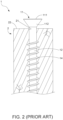
- a conventional screw 1 comprises a head 11, a shank 12 extending axially from the head 11, a drill section 13 disposed on the shank 12 opposite to the head 11, and a plurality of thread convolutions 14 spirally disposed on the shank 12.
- the head 11 has a top surface 111 and a conical surface 112 opposite to the top surface 111.
- the conical surface 112 of the head 11 is connected to the shank 12.
- the object of this invention is to provide a screw capable of breaking fibers, smoothing burrs which cause a ragged edge, and widening spaces for chips accommodation thereby reducing screwing resistance and fitting the screw with a surface of a workpiece levelly.
- the screw of this invention comprises a shank, a head and a drill section disposed on two opposite ends of the shank, and a plurality of thread convolutions spirally formed on the shank.
- the head has a top surface, a conical surface opposite to the top surface and connected to the shank, a plurality of cutting units disposed along an outer edge of the top surface, a plurality of accommodation portions recessedly formed in the conical surface, and a plurality of ridge portions. Every two adjacent ridge portions are separated by one accommodation portion so that the accommodation portions and the ridge portions are arranged by turns and positioned between the cutting units and the shank.
- Each cutting unit has a first wall defining a first edge, a second wall defining a second edge connected to the first edge, and a third edge formed along a junction of the first wall and the second wall.
- the second edge connects between one first wall of one cutting unit and another adjacent first wall of another cutting unit to thereby connect the cutting units one after another.
- Each accommodation portion has a main groove and an auxiliary groove encircling an outer periphery of the main groove so that the auxiliary groove and the main groove are different.
- the main groove extends in the direction of the shank.
- Each ridge portion extends along a junction of every two adjacent auxiliary grooves and situated between every two adjacent main grooves.
- the cutting units assist in cutting fibers around a drilling hole of a workpiece to thereby prevent the head from being tangled with twisting fibers and even burrs which cause a ragged edge of the drilling hole of the workpiece.
- the ridge portions also help cut the fibers into chips and push the chips into the accommodation portions which provide enough spaces for accommodating the chips to thereby attain a tight engagement between the screw and the workpiece, prevent the chips from accumulating around the head unduly, reduce the screwing resistance, and allow the top surface to be flat with a surface of the workpiece.
- an area of each auxiliary groove is smaller than an area of each main groove.
- the number of the cutting units is at least two times larger than the number of the accommodation portions.
- the main grooves are connected to part of the cutting units.
- the auxiliary grooves are connected to the remainder of the cutting units.
- the ridge portions extend respectively along a plurality of references lines defined radially from a center of the conical surface.
- a plurality of references lines are defined radially from a center of the conical surface.
- Each ridge portion extends between each cutting unit and the shank in a direction which is inclined to each corresponding one of the reference lines.
- the screw 3 includes a head 31, a shank 32 having an end connected to the head 31, a drill section 33 disposed on another end of the shank 32 opposite to the head 31, and a plurality of thread convolutions 34 spirally disposed on the shank 32.
- the head 31 has a top surface 311, a conical surface 312 opposite to the top surface 311, a plurality of cutting units 313 connected together in sequence along an outer edge of the top surface 311, a plurality of accommodation portions 314 recessedly formed in the conical surface 312, and a plurality of ridge portions 315 protruding outwards from the conical surface 312.
- Each ridge portion 315 is formed between every two adjacent accommodation portions 314.
- each accommodation portion 314 is formed between every two adjacent ridge portions 315 so that the accommodation portions 314 and the ridge portions 315 are arranged in an alternating manner.
- the accommodation portions 314 and the ridge portions 315 are located between the cutting units 313 and the shank 32.
- a plurality of references lines R are defined radially from a center of the conical surface 312 as shown in Fig. 4 .
- Each ridge portion 315 extends respectively along the references lines R.
- Each accommodation portion 314 expands gradually from the direction of the shank 32 toward the cutting units 313.
- each ridge portion 315 tapers gradually from the direction of the shank 32 toward the cutting units 313.
- each cutting unit 313 has a first wall 3131, a second wall 3132 connected to the first wall 3131, and a third edge 3133 formed along a junction of the first wall 3131 and the second wall 3132.
- the first wall 3131 defines a first edge 3131A which is connected to a second edge 3132A defined by the second wall 3132.
- the second edge 3132A of each second wall 3132 extends from one first wall 3131 of one cutting unit 313 to another first wall 3131 of another cutting unit 313 adjacent to the one first wall 3131 so that the cutting units 313 are arranged in a continuous connecting manner.
- the cutting units 313 connects one after another to form a ladder shape.
- Each accommodation portion 314 has a main groove 3141 and an auxiliary groove 3142 disposed around an outer periphery of the main groove 3141, and that makes the main groove 3141 and the auxiliary groove 3142 different.
- the main groove 3141 is recessedly formed in the conical surface 312 and extend toward the direction of the shank 32.
- Each ridge portion 315 is formed along a junction of every two adjacent auxiliary grooves 3142 of every two adjacent accommodation portions 314 and situated between every two adjacent main grooves 3141.
- the number of the cutting units 313 is two times larger than the number of the accommodation portions 314 so that the main grooves 3141 are connected to part of the cutting units 313 and the auxiliary grooves 3142 are connected to the remainder of the cutting units 313.
- the relation of the number between the cutting units 313 and the accommodation portions 314 can be varied according to needs.
- An area of each auxiliary groove 3142 is smaller than an area of each main groove 3141.
- a screwing operation of the screw 3 begins with positioning the drill section 33 against a surface 42 of a workpiece 4.
- the drill section 33 and the thread convolutions 34 cut downwards into the workpiece 4 and form a drilling hole 41 in the workpiece 4.
- fibers which are not completely severed and chips which are generated by the cutting of the drill section 33 and the thread convolutions 34 will move outwards gradually along the thread convolutions 34.
- the chips and the fibers then accumulate at a periphery of the drilling hole 41 and cause burrs which incur a ragged edge of the workpiece 4, and synchronously the first edges 3131A, the second edges 3132A, and the third edges 3133 of the cutting units 313 are adapted to cut the unsevered fibers into chips to thereby break the fibers effectively, smooth the burrs of the ragged edge of the drilling hole 41, and prevent the head 31 from being entangled in the fibers.
- the screwing resistance is reduced and the screwing operation is accelerated effectively.
- the ridge portions 315 can also assist in cutting the fibers, and simultaneously guiding the chips into the accommodation portions 314.
- each accommodation portion 314 is provided with the main groove 3141 surrounding by the auxiliary groove 3142 whereby the auxiliary groove 3142 is adapted to connect between the main groove 3141 and the corresponding ridge portions 315. Therefore, the chips pushed by the ridge portions 315 can enter into the main groove 3141 through the auxiliary groove 3142 smoothly and quickly. Further, the accommodation portions 314 enlarge spaces for holding the chips to thereby attain a tight engagement between the screw 3 and the workpiece 4, prevent the chips from being unduly accumulated around the head 31, improve the surface flatness of the screw 3 after the screw 3 is embedded in the workpiece 4, and prevent the workpiece 4 from cracking caused by pressing the unduly accumulated chips.
- each ridge portion 315 extends between each cutting unit 313 and the shank 32 in a direction which is inclined to each corresponding one of the reference lines R.
- An inclined direction of the ridge portions 315 can be varied according to needs.
- the screwing direction of the screw 3 facilitates the cutting operation of the ridge portions 315 to thereby cut the fibers into chips entirely.
- the ridge portions 315 further push the chips into the accommodation portions 314 to thereby avoid unduly accumulated chips, decrease the screwing resistance, and allow the screw 3 to be embedded into the workpiece 4 (not shown) levelly and entirely.
- the screw of this invention takes advantages of the cutting units connected continuously along the outer edge of the top surface to sever the fibers and smooth the burrs causing the ragged edge of the workpiece to thereby prevent the head from entwining with the fibers and reduce the screwing resistance.
- the ridge portions assist in cutting the fibers and leading the chips into the accommodation portions.
- the accommodation portions also help extend spaces for accommodating the chips. Hence, the screw and the workpiece are engaged tightly. The chips will not accumulate around the head unduly. The screwing resistance is reduced.
- the screw is embedded in the workpiece levelly.
Landscapes
- Engineering & Computer Science (AREA)
- General Engineering & Computer Science (AREA)
- Mechanical Engineering (AREA)
- Life Sciences & Earth Sciences (AREA)
- Chemical & Material Sciences (AREA)
- Dispersion Chemistry (AREA)
- Wood Science & Technology (AREA)
- Drilling Tools (AREA)
Priority Applications (1)
| Application Number | Priority Date | Filing Date | Title |
|---|---|---|---|
| EP23182342.8A EP4484772B1 (fr) | 2023-06-29 | 2023-06-29 | Vis |
Applications Claiming Priority (1)
| Application Number | Priority Date | Filing Date | Title |
|---|---|---|---|
| EP23182342.8A EP4484772B1 (fr) | 2023-06-29 | 2023-06-29 | Vis |
Publications (2)
| Publication Number | Publication Date |
|---|---|
| EP4484772A1 true EP4484772A1 (fr) | 2025-01-01 |
| EP4484772B1 EP4484772B1 (fr) | 2025-08-20 |
Family
ID=87060393
Family Applications (1)
| Application Number | Title | Priority Date | Filing Date |
|---|---|---|---|
| EP23182342.8A Active EP4484772B1 (fr) | 2023-06-29 | 2023-06-29 | Vis |
Country Status (1)
| Country | Link |
|---|---|
| EP (1) | EP4484772B1 (fr) |
Citations (3)
| Publication number | Priority date | Publication date | Assignee | Title |
|---|---|---|---|---|
| US8348575B2 (en) * | 2008-12-19 | 2013-01-08 | Illinois Tool Works Inc. | Self-counter-sinking screw with circumferential cutters |
| US20180245620A1 (en) * | 2013-08-29 | 2018-08-30 | Shu-Chin Huang | Screw capable of easily drilling holes and dregs removing |
| US20230047308A1 (en) * | 2021-08-11 | 2023-02-16 | Taiwan Shan Yin International Co., Ltd. | Screw |
-
2023
- 2023-06-29 EP EP23182342.8A patent/EP4484772B1/fr active Active
Patent Citations (3)
| Publication number | Priority date | Publication date | Assignee | Title |
|---|---|---|---|---|
| US8348575B2 (en) * | 2008-12-19 | 2013-01-08 | Illinois Tool Works Inc. | Self-counter-sinking screw with circumferential cutters |
| US20180245620A1 (en) * | 2013-08-29 | 2018-08-30 | Shu-Chin Huang | Screw capable of easily drilling holes and dregs removing |
| US20230047308A1 (en) * | 2021-08-11 | 2023-02-16 | Taiwan Shan Yin International Co., Ltd. | Screw |
Also Published As
| Publication number | Publication date |
|---|---|
| EP4484772B1 (fr) | 2025-08-20 |
Similar Documents
| Publication | Publication Date | Title |
|---|---|---|
| US12215728B2 (en) | Screw | |
| EP3460263B1 (fr) | Vis à vissage rapide | |
| US20250003440A1 (en) | Screw | |
| US20190113066A1 (en) | Wood screw | |
| US20200056647A1 (en) | Fastener | |
| US20200096034A1 (en) | Screw capable of reducing drilling torque | |
| US20050170696A1 (en) | Braid cutting apparatus | |
| EP4484772A1 (fr) | Vis | |
| US20250012312A1 (en) | Screw | |
| US11835077B2 (en) | Screw | |
| TWI797710B (zh) | 螺絲 | |
| US20250180057A1 (en) | Screw | |
| EP3550160B1 (fr) | Pièce de fixation | |
| EP4134557B1 (fr) | Vis à angles de filetage multiples | |
| EP4488532B1 (fr) | Vis | |
| EP4484770A1 (fr) | Vis | |
| CA2295256C (fr) | Fil pour piece rapportee helicoidale | |
| EP3974665B1 (fr) | Vis anti-arrachement et à faible résistance | |
| EP3366933B1 (fr) | Vis | |
| EP4563831A1 (fr) | Vis | |
| US20230048078A1 (en) | Screw with multiple thread angles | |
| EP4567288A1 (fr) | Vis | |
| US20250172168A1 (en) | Screw | |
| US2096810A (en) | Thread cutting device | |
| US20250327475A1 (en) | Screw |
Legal Events
| Date | Code | Title | Description |
|---|---|---|---|
| PUAI | Public reference made under article 153(3) epc to a published international application that has entered the european phase |
Free format text: ORIGINAL CODE: 0009012 |
|
| STAA | Information on the status of an ep patent application or granted ep patent |
Free format text: STATUS: REQUEST FOR EXAMINATION WAS MADE |
|
| 17P | Request for examination filed |
Effective date: 20241030 |
|
| AK | Designated contracting states |
Kind code of ref document: A1 Designated state(s): AL AT BE BG CH CY CZ DE DK EE ES FI FR GB GR HR HU IE IS IT LI LT LU LV MC ME MK MT NL NO PL PT RO RS SE SI SK SM TR |
|
| GRAP | Despatch of communication of intention to grant a patent |
Free format text: ORIGINAL CODE: EPIDOSNIGR1 |
|
| STAA | Information on the status of an ep patent application or granted ep patent |
Free format text: STATUS: GRANT OF PATENT IS INTENDED |
|
| INTG | Intention to grant announced |
Effective date: 20250311 |
|
| GRAS | Grant fee paid |
Free format text: ORIGINAL CODE: EPIDOSNIGR3 |
|
| GRAA | (expected) grant |
Free format text: ORIGINAL CODE: 0009210 |
|
| STAA | Information on the status of an ep patent application or granted ep patent |
Free format text: STATUS: THE PATENT HAS BEEN GRANTED |
|
| AK | Designated contracting states |
Kind code of ref document: B1 Designated state(s): AL AT BE BG CH CY CZ DE DK EE ES FI FR GB GR HR HU IE IS IT LI LT LU LV MC ME MK MT NL NO PL PT RO RS SE SI SK SM TR |
|
| REG | Reference to a national code |
Ref country code: GB Ref legal event code: FG4D |
|
| REG | Reference to a national code |
Ref country code: CH Ref legal event code: EP |
|
| REG | Reference to a national code |
Ref country code: IE Ref legal event code: FG4D |
|
| REG | Reference to a national code |
Ref country code: DE Ref legal event code: R096 Ref document number: 602023005830 Country of ref document: DE |
|
| REG | Reference to a national code |
Ref country code: SE Ref legal event code: TRGR |
|
| P01 | Opt-out of the competence of the unified patent court (upc) registered |
Free format text: CASE NUMBER: UPC_APP_7259_4484772/2025 Effective date: 20250916 |
|
| REG | Reference to a national code |
Ref country code: NL Ref legal event code: MP Effective date: 20250820 |
|
| PG25 | Lapsed in a contracting state [announced via postgrant information from national office to epo] |
Ref country code: IS Free format text: LAPSE BECAUSE OF FAILURE TO SUBMIT A TRANSLATION OF THE DESCRIPTION OR TO PAY THE FEE WITHIN THE PRESCRIBED TIME-LIMIT Effective date: 20251220 |
|
| REG | Reference to a national code |
Ref country code: LT Ref legal event code: MG9D |
|
| PG25 | Lapsed in a contracting state [announced via postgrant information from national office to epo] |
Ref country code: PT Free format text: LAPSE BECAUSE OF FAILURE TO SUBMIT A TRANSLATION OF THE DESCRIPTION OR TO PAY THE FEE WITHIN THE PRESCRIBED TIME-LIMIT Effective date: 20251222 |
|
| PG25 | Lapsed in a contracting state [announced via postgrant information from national office to epo] |
Ref country code: FI Free format text: LAPSE BECAUSE OF FAILURE TO SUBMIT A TRANSLATION OF THE DESCRIPTION OR TO PAY THE FEE WITHIN THE PRESCRIBED TIME-LIMIT Effective date: 20250820 |
|
| PG25 | Lapsed in a contracting state [announced via postgrant information from national office to epo] |
Ref country code: HR Free format text: LAPSE BECAUSE OF FAILURE TO SUBMIT A TRANSLATION OF THE DESCRIPTION OR TO PAY THE FEE WITHIN THE PRESCRIBED TIME-LIMIT Effective date: 20250820 Ref country code: NL Free format text: LAPSE BECAUSE OF FAILURE TO SUBMIT A TRANSLATION OF THE DESCRIPTION OR TO PAY THE FEE WITHIN THE PRESCRIBED TIME-LIMIT Effective date: 20250820 |
|
| PG25 | Lapsed in a contracting state [announced via postgrant information from national office to epo] |
Ref country code: GR Free format text: LAPSE BECAUSE OF FAILURE TO SUBMIT A TRANSLATION OF THE DESCRIPTION OR TO PAY THE FEE WITHIN THE PRESCRIBED TIME-LIMIT Effective date: 20251121 |
|
| PG25 | Lapsed in a contracting state [announced via postgrant information from national office to epo] |
Ref country code: LV Free format text: LAPSE BECAUSE OF FAILURE TO SUBMIT A TRANSLATION OF THE DESCRIPTION OR TO PAY THE FEE WITHIN THE PRESCRIBED TIME-LIMIT Effective date: 20250820 |
|
| PG25 | Lapsed in a contracting state [announced via postgrant information from national office to epo] |
Ref country code: PL Free format text: LAPSE BECAUSE OF FAILURE TO SUBMIT A TRANSLATION OF THE DESCRIPTION OR TO PAY THE FEE WITHIN THE PRESCRIBED TIME-LIMIT Effective date: 20250820 Ref country code: BG Free format text: LAPSE BECAUSE OF FAILURE TO SUBMIT A TRANSLATION OF THE DESCRIPTION OR TO PAY THE FEE WITHIN THE PRESCRIBED TIME-LIMIT Effective date: 20250820 |
|
| PG25 | Lapsed in a contracting state [announced via postgrant information from national office to epo] |
Ref country code: RS Free format text: LAPSE BECAUSE OF FAILURE TO SUBMIT A TRANSLATION OF THE DESCRIPTION OR TO PAY THE FEE WITHIN THE PRESCRIBED TIME-LIMIT Effective date: 20251120 |
|
| PG25 | Lapsed in a contracting state [announced via postgrant information from national office to epo] |
Ref country code: ES Free format text: LAPSE BECAUSE OF FAILURE TO SUBMIT A TRANSLATION OF THE DESCRIPTION OR TO PAY THE FEE WITHIN THE PRESCRIBED TIME-LIMIT Effective date: 20250820 |
|
| REG | Reference to a national code |
Ref country code: AT Ref legal event code: MK05 Ref document number: 1827575 Country of ref document: AT Kind code of ref document: T Effective date: 20250820 |
|
| PG25 | Lapsed in a contracting state [announced via postgrant information from national office to epo] |
Ref country code: SM Free format text: LAPSE BECAUSE OF FAILURE TO SUBMIT A TRANSLATION OF THE DESCRIPTION OR TO PAY THE FEE WITHIN THE PRESCRIBED TIME-LIMIT Effective date: 20250820 |
|
| PG25 | Lapsed in a contracting state [announced via postgrant information from national office to epo] |
Ref country code: DK Free format text: LAPSE BECAUSE OF FAILURE TO SUBMIT A TRANSLATION OF THE DESCRIPTION OR TO PAY THE FEE WITHIN THE PRESCRIBED TIME-LIMIT Effective date: 20250820 |
|
| PG25 | Lapsed in a contracting state [announced via postgrant information from national office to epo] |
Ref country code: AT Free format text: LAPSE BECAUSE OF FAILURE TO SUBMIT A TRANSLATION OF THE DESCRIPTION OR TO PAY THE FEE WITHIN THE PRESCRIBED TIME-LIMIT Effective date: 20250820 |
|
| PG25 | Lapsed in a contracting state [announced via postgrant information from national office to epo] |
Ref country code: IT Free format text: LAPSE BECAUSE OF FAILURE TO SUBMIT A TRANSLATION OF THE DESCRIPTION OR TO PAY THE FEE WITHIN THE PRESCRIBED TIME-LIMIT Effective date: 20250820 |