EP4484879A2 - Commande de cristallisation active dans des systèmes de stockage thermique de matériau à changement de phase - Google Patents
Commande de cristallisation active dans des systèmes de stockage thermique de matériau à changement de phase Download PDFInfo
- Publication number
- EP4484879A2 EP4484879A2 EP24213058.1A EP24213058A EP4484879A2 EP 4484879 A2 EP4484879 A2 EP 4484879A2 EP 24213058 A EP24213058 A EP 24213058A EP 4484879 A2 EP4484879 A2 EP 4484879A2
- Authority
- EP
- European Patent Office
- Prior art keywords
- phase change
- change material
- heat
- storage system
- pcm
- Prior art date
- Legal status (The legal status is an assumption and is not a legal conclusion. Google has not performed a legal analysis and makes no representation as to the accuracy of the status listed.)
- Pending
Links
Images


Classifications
-
- F—MECHANICAL ENGINEERING; LIGHTING; HEATING; WEAPONS; BLASTING
- F25—REFRIGERATION OR COOLING; COMBINED HEATING AND REFRIGERATION SYSTEMS; HEAT PUMP SYSTEMS; MANUFACTURE OR STORAGE OF ICE; LIQUEFACTION SOLIDIFICATION OF GASES
- F25B—REFRIGERATION MACHINES, PLANTS OR SYSTEMS; COMBINED HEATING AND REFRIGERATION SYSTEMS; HEAT PUMP SYSTEMS
- F25B21/00—Machines, plants or systems, using electric or magnetic effects
- F25B21/02—Machines, plants or systems, using electric or magnetic effects using Peltier effect; using Nernst-Ettinghausen effect
-
- F—MECHANICAL ENGINEERING; LIGHTING; HEATING; WEAPONS; BLASTING
- F28—HEAT EXCHANGE IN GENERAL
- F28D—HEAT-EXCHANGE APPARATUS, NOT PROVIDED FOR IN ANOTHER SUBCLASS, IN WHICH THE HEAT-EXCHANGE MEDIA DO NOT COME INTO DIRECT CONTACT
- F28D20/00—Heat storage plants or apparatus in general; Regenerative heat-exchange apparatus not covered by groups F28D17/00 or F28D19/00
- F28D20/02—Heat storage plants or apparatus in general; Regenerative heat-exchange apparatus not covered by groups F28D17/00 or F28D19/00 using latent heat
- F28D20/021—Heat storage plants or apparatus in general; Regenerative heat-exchange apparatus not covered by groups F28D17/00 or F28D19/00 using latent heat the latent heat storage material and the heat-exchanging means being enclosed in one container
-
- F—MECHANICAL ENGINEERING; LIGHTING; HEATING; WEAPONS; BLASTING
- F28—HEAT EXCHANGE IN GENERAL
- F28D—HEAT-EXCHANGE APPARATUS, NOT PROVIDED FOR IN ANOTHER SUBCLASS, IN WHICH THE HEAT-EXCHANGE MEDIA DO NOT COME INTO DIRECT CONTACT
- F28D20/00—Heat storage plants or apparatus in general; Regenerative heat-exchange apparatus not covered by groups F28D17/00 or F28D19/00
- F28D20/02—Heat storage plants or apparatus in general; Regenerative heat-exchange apparatus not covered by groups F28D17/00 or F28D19/00 using latent heat
- F28D20/028—Control arrangements therefor
-
- F—MECHANICAL ENGINEERING; LIGHTING; HEATING; WEAPONS; BLASTING
- F25—REFRIGERATION OR COOLING; COMBINED HEATING AND REFRIGERATION SYSTEMS; HEAT PUMP SYSTEMS; MANUFACTURE OR STORAGE OF ICE; LIQUEFACTION SOLIDIFICATION OF GASES
- F25B—REFRIGERATION MACHINES, PLANTS OR SYSTEMS; COMBINED HEATING AND REFRIGERATION SYSTEMS; HEAT PUMP SYSTEMS
- F25B2321/00—Details of machines, plants or systems, using electric or magnetic effects
- F25B2321/02—Details of machines, plants or systems, using electric or magnetic effects using Peltier effects; using Nernst-Ettinghausen effects
- F25B2321/021—Control thereof
-
- Y—GENERAL TAGGING OF NEW TECHNOLOGICAL DEVELOPMENTS; GENERAL TAGGING OF CROSS-SECTIONAL TECHNOLOGIES SPANNING OVER SEVERAL SECTIONS OF THE IPC; TECHNICAL SUBJECTS COVERED BY FORMER USPC CROSS-REFERENCE ART COLLECTIONS [XRACs] AND DIGESTS
- Y02—TECHNOLOGIES OR APPLICATIONS FOR MITIGATION OR ADAPTATION AGAINST CLIMATE CHANGE
- Y02E—REDUCTION OF GREENHOUSE GAS [GHG] EMISSIONS, RELATED TO ENERGY GENERATION, TRANSMISSION OR DISTRIBUTION
- Y02E60/00—Enabling technologies; Technologies with a potential or indirect contribution to GHG emissions mitigation
- Y02E60/14—Thermal energy storage
Definitions
- the present invention relates to phase change materials (PCMs) which store and release thermal energy by undergoing melt/crystallisation cycles.
- PCMs phase change materials
- Phase change materials store and release thermal energy by undergoing melt/crystallisation cycles.
- Nucleation the first step of the crystallisation process, may not occur due to the PCM sub-cooling (remaining below its melting point but not crystallising), or may occur spontaneously at differing temperatures, or at different times or differing between cooling rates etc.
- Nucleation can also be initiated by addition of a seed crystal.
- this can be done via adding a seed crystal (i.e. similar to dropping in a seed crystal to a sub-cooled solution or liquid to initiate crystallisation in the bulk) via a mechanical means, i.e. a crystal dropper or similar; or having a region when some material is crystallised.
- a mechanical means i.e. a crystal dropper or similar; or having a region when some material is crystallised.
- Contact with crystallised material and the bulk sub-cooled solution/liquid can be made, and then unmade; or releasing a seed crystal from a confined geometry where the seed crystal exists but is not in sufficiently direct contact with the bulk sub-cooled solution or liquid to cause crystallisation of the bulk until the moment of release, i.e. a material with cracks, such as a stamped metal plate/disk may have.
- these may be microscopic cracks where seed crystals can reside above their normal melting point, and when these are activated, e.g. flexed, then the cracks open up and release seed crystals resulting in crystallisation of the bulk solution/liquid.
- the method of utilising seed crystals to initiate crystallisation can be applied in primarily two methods: actively and passively.
- an active method a mechanism is activated (e.g. through an electronic signal, presence of water flow, mechanical button, external pressure differential) where a seed crystal is released or added to the bulk solution/liquid resulting in bulk crystallisation.
- this may be, e.g.
- a crystal dropping mechanism a plate/disk of metal which is deformed/flexed through mechanical means, or that changes geometry/shape when electricity/an electrical field is passed through it/applied, or a valve that can open which makes contact between a sample of crystallised material and the bulk sub-cooled solution/liquid, or as opposed to a valve, a sample of crystallised material can be 'dunked' in the sub-cooled solution/liquid and then 'un-dunked'. For example, this may be on a tip of a needle/thin rod etc.
- the seed crystals are generated without an external mechanism but are initiated by the temperature of the bulk material, i.e.
- this may be a submerged metal plate/disk which is e.g. bimetallic, and flexes as needed at the set temperature and then releases seed crystals, which initiates bulk crystallisation.
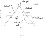
- the effect of this is to have a material where the effect of sub-cooling is not significantly observable.
- a related problem is a nucleation additive used to prevent sub-cooling passively may lose its nucleator properties through a thermally driven 'deactivation process'.
- a nucleator is required to be a specific hydrate, then this hydrate can melt/dehydrate.
- An actively controlled thermal region within the PCM containment can therefore also be used to keep a nucleator functional.
- PCM phase-change material
- thermo storage system where sub-cooled phase change material (PCM) is nucleated via a controlled thermal region(s).
- PCM phase change material
- a cold shock may be described as a small region within the sub-cooled PCM which is sufficiently cold to initiate nucleation.
- a method of using PCMs where the PCM is housed in a containment vessel and has a heat exchanger internally, to permit the transfer of heat or coolth (thermal energy) into/out of the PCM.
- the cold shock may be generated via a thermoelectric device, or a compression vapor cycle device, or a heat pipe, or a switchable heat pipe, or cooling an area in thermal contact with the PCM with a cold material, i.e. dry ice, liquid nitrogen, or the rapid expansion of a material which evaporates very endothermically.
- a cold material i.e. dry ice, liquid nitrogen, or the rapid expansion of a material which evaporates very endothermically.
- PCM system which does not exhibit sub-cooling upon discharge due to the presence of a cold spot maintained thermoelectrically, or by a compression vapor cycle, or by a heat pipe, or by a switchable heat pipe, that actively keeps some PCM crystalline at all times.
- PCM system which does not exhibit sub-cooling upon discharge due to the presence of a cold spot maintained thermoelectrically, or by a compression vapor cycle, or by a heat pipe, or by a switchable heat pipe, that actively keeps some PCM crystalline when the PCM approaches its melting point.
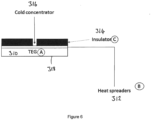
- thermoelectric device consists of one or more thermoelectric devices stacked, optionally with heat spreaders between thermoelectric interfaces, a final cold face with a heat spreader with thermal insulator to create a cold concentrator.
- thermoelectric device in contact with the PCM and the hot side of the thermoelectric device is in thermal contact with either: the ambient, the PCM heat exchanger or another PCM storage system.
- thermoelectric device has a cold concentrator
- thermoelectric device or a compression vapor cycle device, or a heat pipe, or a switchable heat pipe
- the hot side of the thermoelectric device or a compression vapor cycle device, or a heat pipe, or a switchable heat pipe, is in thermal contact with either: the ambient, the PCM heat exchanger or another PCM store.
- thermoelectric device there is also described a system where an electrical store is charged by the thermoelectric device, the same thermoelectric device then utilises the same electrical store to generate coolth to function at a later time.
- thermoelectric device or a compression vapor cycle device
- an electrical store where said electrical store is charged from local electrical supply (e.g. network electricity, 12v/24v/48v vehicle system).
- thermoelectric device is controlled via PWM or preferably direct-drive.
- thermoelectric device either in, or locally to the thermoelectric device, or a compression vapor cycle device, or a heat pipe, or a switchable heat pipe, provides information feedback, to for example, the power electronics.
- a method to use PCMs is to house the PCM in a containment vessel and to have a heat exchanger internally, to permit the transfer of heat or coolth (thermal energy) into/out of the PCM.
- FIG. 1 is a representation of a heat storage system 10 comprising a heat exchanger 18 located within a containment vessel 12.
- the heat exchanger 18 is immersed in PCM 11 which is contained within the containment vessel 12.
- the heat exchanger 18 has an input 14 and an output 16.
- the heat exchanger 18 functions to transfer heat in and/or out the heat storage system. Any number and type of heat exchangers may be used.
- FIG. 1 also shows a cold shock area set-up generally represented by the reference numeral 20.
- the cold shock area 20 has been expanded and is located at the top of the containment vessel 10. As shown in the expanded area there is a cold shock 22 located adjacent to thermoelectric devices (TEG) 24, 26 and a heat exchange pipe (HX pipe) 28. Electrical leads 30 are also shown attached to the thermoelectric devices 24, 26.
- TOG thermoelectric devices
- HX pipe heat exchange pipe
- FIG. 2 is a representation of a further heat storage system 100.
- the heat storage system 100 contains a PCM 111 within a containment vessel 112.
- a heat exchanger 118 is immersed in the PCM 111.
- the heat exchanger 118 has an input 114 and an output 116.
- the heat exchanger 118 functions to transfer heat in and/or out for the heat storage system 100. Any number and type of heat exchangers may be used.
- a cold shock area 120 located at the bottom of the containment vessel 112.
- the cold shock area 120 is expanded in size where it can be seen there is a cold spot 128.
- insulation areas 124, 126 are Located under the insulation areas 124, 126 there is a heat sink 122.
- the heat sink is the ambient through a heat sink external to the containment vessel 112.
- thermoelectric devices operate using the Peltier effect, and results in a heat pump type effect on a small, solid-state, scale.
- a thermoelectric device is typically a rectangular plate of thickness less than 10mm, with a ceramic coating on the two large faces. When an electrical current is passed through the thermoelectric device, heat is generated on one face, and coolth on the other. Such a thermoelectric device is used in the heat storage system 10 shown in Figure 1 .
- Compression vapor cycle devices utilise the boiling (or evaporation), of a fluid to provide cooling, generally in a closed loop where the reverse process (condensation) also occurs at a different location (or the same).
- a heat pipe, or a switchable heat pipe are objects that have a liquid or gas inside them that are sealed and there is a change of phase when heat or cold is applied to one or more region of the object.
- the effect is an object that can show (optionally if switchable) high levels of thermal conductivity at certain temperatures or temperature ranges.
- the PCM must be fully melted if it is to sub-cool. If the material is not fully melted, then the material will not sub-cool.
- Sub-cooling can be passively avoided if a nucleating agent is used (an additive that prevents sub-cooling by providing an area/surface for crystal growth).
- nucleating agents can be optimised by controlling where they are located and how they are contained, i.e. in a mesh or porous material.
- a PCM has no known sufficient method (e.g. an additive) to ensure consistent nucleation, then that may prevent its use.
- a method to overcome that would be to design a containment that has a thermoelectrically driven "cold spot", where crystals of the bulk PCM (or other relevant crystals) are kept in the unmelted state. This is a focus of the present application.
- the mass of these crystals can be very small - they are seed crystals that provide a point of growth. It is an advantage to keep this mass of crystals small. This mass of crystals requires to be continuously cooled when the bulk PCM is in the charged (molten) state, and so is preferably minimised.
- the power consumption of the cooling spot is proportional to the heat transfer rate from the bulk PCM to the cold spot - hence it has been found to be preferable to have a measure of insulation between the cold spot with crystals and the bulk of PCM.
- An alternative is to use the cold spot to protect a nucleating agent, as opposed to the PCM.
- a nucleation additive used to prevent sub-cooling passively may lose its nucleator properties through a thermally driven 'deactivation process'.
- nucleator is required to be a specific hydrate, then this hydrate can melt/dehydrate.
- An actively controlled thermal region within the PCM containment can therefore be used to keep a nucleator functional.
- thermoelectric device or a compression vapor cycle device, or a heat pipe, or a switchable heat pipe, does not need to run as often. This reduces running costs and extends lifetime, since the temperature of the cold spot is above the bulk temperature of the PCM.
- the optimisation is also applicable to a compression vapor cycle device.
- the optimisation is also applicable to a heat pipe, or a switchable heat pipe.
- the use of one or multiple of heat pipes on either the hot or cold side of a thermoelectric device (TEG or TED) further enhances the control over thermal regions.
- thermoelectric device When a thermoelectric device has a temperature differential between its two faces, it is possible to, "in effect” - run the thermoelectric device backwards and generate electricity from this temperature differential, rather than create a temperature differential from electricity. This can be used to charge said electrical store.
- a small, cold resistant, electrical store triggers a cold shock to a PCM that is integrated in a fuel cell vehicle which is being used in an ambient temperature that is not permissible towards the operation of a fuel cell.
- the fuel cell requires pre-heating before use. This can be accomplished by activating the PCM store via a cold shock.
- the fuel cell vehicle may be: an electric battery based system such as Li-ion batteries; a combustion engine; or an emergency heat source (survival suit).
- thermoelectric device(s) can initiate the PCM system which generates heat that can be transferred to other systems, rendering these other systems operational.
- thermoelectric devices require a DC power supply.
- thermoelectric devices require a relatively high amperage, low voltage DC power supply. It can be beneficial to modulate the power of the thermoelectric device.
- thermoelectric power modulation pulse wave modification (PWM) or direct-drive.
- PWM pulse wave modification
- Direct drive is preferable for reduced power consumption.
- thermoelectric device To prevent contamination of the internal electrical components of a thermoelectric device, or a compression vapor cycle device, it may be preferable to protect the electrical components of the thermoelectric device, or a compression vapor cycle device with a waterproof/PCM proof material.
- Non-limiting examples of such are: electrical potting compounds; silicone sealant; glues etc.
Landscapes
- Engineering & Computer Science (AREA)
- Physics & Mathematics (AREA)
- Thermal Sciences (AREA)
- Mechanical Engineering (AREA)
- General Engineering & Computer Science (AREA)
- Cooling Or The Like Of Electrical Apparatus (AREA)
- Devices That Are Associated With Refrigeration Equipment (AREA)
- Organic Low-Molecular-Weight Compounds And Preparation Thereof (AREA)
- Control Of Temperature (AREA)
- Secondary Cells (AREA)
Applications Claiming Priority (3)
| Application Number | Priority Date | Filing Date | Title |
|---|---|---|---|
| GBGB1708724.8A GB201708724D0 (en) | 2017-06-01 | 2017-06-01 | Active crystallisation control in phase-change material thermal storage systems |
| EP18730063.7A EP3631339A1 (fr) | 2017-06-01 | 2018-05-31 | Commande de cristallisation active dans des systèmes de stockage thermique de matériau à changement de phase |
| PCT/GB2018/051483 WO2018220378A1 (fr) | 2017-06-01 | 2018-05-31 | Commande de cristallisation active dans des systèmes de stockage thermique de matériau à changement de phase |
Related Parent Applications (1)
| Application Number | Title | Priority Date | Filing Date |
|---|---|---|---|
| EP18730063.7A Division EP3631339A1 (fr) | 2017-06-01 | 2018-05-31 | Commande de cristallisation active dans des systèmes de stockage thermique de matériau à changement de phase |
Publications (2)
| Publication Number | Publication Date |
|---|---|
| EP4484879A2 true EP4484879A2 (fr) | 2025-01-01 |
| EP4484879A3 EP4484879A3 (fr) | 2025-04-09 |
Family
ID=59350023
Family Applications (2)
| Application Number | Title | Priority Date | Filing Date |
|---|---|---|---|
| EP18730063.7A Withdrawn EP3631339A1 (fr) | 2017-06-01 | 2018-05-31 | Commande de cristallisation active dans des systèmes de stockage thermique de matériau à changement de phase |
| EP24213058.1A Pending EP4484879A3 (fr) | 2017-06-01 | 2018-05-31 | Commande de cristallisation active dans des systèmes de stockage thermique de matériau à changement de phase |
Family Applications Before (1)
| Application Number | Title | Priority Date | Filing Date |
|---|---|---|---|
| EP18730063.7A Withdrawn EP3631339A1 (fr) | 2017-06-01 | 2018-05-31 | Commande de cristallisation active dans des systèmes de stockage thermique de matériau à changement de phase |
Country Status (9)
| Country | Link |
|---|---|
| US (1) | US11378345B2 (fr) |
| EP (2) | EP3631339A1 (fr) |
| JP (1) | JP7311082B2 (fr) |
| KR (1) | KR102606036B1 (fr) |
| CN (1) | CN110770524B (fr) |
| AU (1) | AU2018276134B2 (fr) |
| CA (1) | CA3065247A1 (fr) |
| GB (1) | GB201708724D0 (fr) |
| WO (1) | WO2018220378A1 (fr) |
Families Citing this family (2)
| Publication number | Priority date | Publication date | Assignee | Title |
|---|---|---|---|---|
| CN113150972A (zh) * | 2021-02-27 | 2021-07-23 | 蒋建国 | 一种有机废物生物分解用自动控温装置 |
| EP4665096A1 (fr) * | 2024-06-12 | 2025-12-17 | Siemens Aktiengesellschaft | Procédé et appareil de dissipation de chaleur d'un système électrique |
Citations (1)
| Publication number | Priority date | Publication date | Assignee | Title |
|---|---|---|---|---|
| WO2011058383A2 (fr) | 2009-11-16 | 2011-05-19 | Sunamp Limited | Systèmes de stockage d'énergie |
Family Cites Families (26)
| Publication number | Priority date | Publication date | Assignee | Title |
|---|---|---|---|---|
| US4199021A (en) * | 1976-11-24 | 1980-04-22 | Johnson Controls, Inc. | Thermal energy storage apparatus |
| CA1115264A (fr) * | 1977-04-26 | 1981-12-29 | Calvin D. Maccracken | Methode et systeme d'emmagasinage sous forme compacte de la chaleur et du froid a l'aide de matieres a phase modifiable |
| US4258696A (en) * | 1978-04-05 | 1981-03-31 | Johnson Controls, Inc. | Passive thermal energy phase change storage apparatus |
| DE3029780A1 (de) | 1980-08-04 | 1982-03-04 | Rudolf 1000 Berlin Termont | Verfahren und massnahmen zur ausloesung der kristallisation unterkuehlter schmelzen |
| DE3044202C2 (de) | 1980-11-24 | 1982-10-07 | Alfred Schneider KG, 7630 Lahr | Verfahren und Vorrichtung zum Einbringen von Kristallisationskeimen in ein flüssiges Latentwärmespeichermedium |
| JPH0760075B2 (ja) * | 1987-01-31 | 1995-06-28 | 株式会社東芝 | 蓄熱装置 |
| JPH01302099A (ja) * | 1988-05-31 | 1989-12-06 | Toshiba Corp | 蓄熱装置 |
| JP2535603B2 (ja) * | 1988-10-31 | 1996-09-18 | 株式会社東芝 | 蓄熱装置 |
| JPH06252285A (ja) * | 1993-02-24 | 1994-09-09 | Fuji Xerox Co Ltd | 回路基板 |
| AU6859294A (en) * | 1993-05-25 | 1994-12-20 | Industrial Research Limited | A peltier device |
| CA2208695C (fr) | 1996-06-25 | 2007-03-20 | Kenji Saita | Systeme pour emmagasiner la chaleur et methode pour controler l'evacuation de la chaleur |
| JP3588630B2 (ja) | 2000-09-06 | 2004-11-17 | 独立行政法人産業技術総合研究所 | 蓄熱式加熱体 |
| DE10303498A1 (de) * | 2003-01-30 | 2004-08-12 | Robert Bosch Gmbh | Vorrichtung und Verfahren zur Kühlung des Wärmematerials eines Latentwärmespeichers |
| WO2009065182A1 (fr) * | 2007-11-23 | 2009-05-28 | Cool Or Cosy Energy Technology Pty Ltd | Accumulateur thermique |
| GB0808930D0 (en) * | 2008-05-16 | 2008-06-25 | Sunamp Ltd | Energy Storage system |
| SE535370C2 (sv) * | 2009-08-03 | 2012-07-10 | Skanska Sverige Ab | Anordning och metod för lagring av termisk energi |
| DE102009028863A1 (de) * | 2009-08-25 | 2011-03-03 | Robert Bosch Gmbh | Latentwärmespeicher und Verfahren zum Temperieren einer Brennkraftmaschine |
| DE102011002424B4 (de) | 2011-01-04 | 2013-03-14 | Robert Bosch Gmbh | Verfahren zur Startdiagnose eines Wärmespeichermaterials |
| US20130019849A1 (en) * | 2011-07-22 | 2013-01-24 | Aerojet-General Corporation | Waste heat recovery for forced convection biomass stove |
| WO2013063444A1 (fr) * | 2011-10-28 | 2013-05-02 | Ballnik Douglas P | Procédé et appareil agissant sur la régulation de la température corporelle |
| DE102013220281A1 (de) | 2013-10-08 | 2015-04-09 | Robert Bosch Gmbh | Vorrichtung und Verfahren zum Vorheizen von Motoröl für die Startphase eines Verbrennungsmotors |
| US9366483B2 (en) * | 2013-11-27 | 2016-06-14 | Tokitac LLC | Temperature-controlled container systems for use within a refrigeration device |
| DE102014208616A1 (de) | 2014-05-08 | 2015-11-12 | Robert Bosch Gmbh | Wärmespeichervorrichtung und Verfahren zum Auslösen einer Kristallisation eines Wärmespeichermaterials |
| JP2016006370A (ja) * | 2014-05-29 | 2016-01-14 | パナソニックIpマネジメント株式会社 | 潜熱蓄熱材における結晶核形成方法及び蓄熱装置 |
| CN107735638A (zh) * | 2015-06-10 | 2018-02-23 | 金瑟姆股份有限公司 | 具有改进的传热和隔热特征的运载工具电池热电模块 |
| US9873350B2 (en) * | 2015-09-16 | 2018-01-23 | Ford Global Technologies, Llc | Hybrid vehicle and method of conditioning a vehicle battery |
-
2017
- 2017-06-01 GB GBGB1708724.8A patent/GB201708724D0/en not_active Ceased
-
2018
- 2018-05-31 CN CN201880035760.2A patent/CN110770524B/zh active Active
- 2018-05-31 US US16/617,276 patent/US11378345B2/en active Active
- 2018-05-31 EP EP18730063.7A patent/EP3631339A1/fr not_active Withdrawn
- 2018-05-31 AU AU2018276134A patent/AU2018276134B2/en active Active
- 2018-05-31 JP JP2019564400A patent/JP7311082B2/ja active Active
- 2018-05-31 WO PCT/GB2018/051483 patent/WO2018220378A1/fr not_active Ceased
- 2018-05-31 KR KR1020197038810A patent/KR102606036B1/ko active Active
- 2018-05-31 EP EP24213058.1A patent/EP4484879A3/fr active Pending
- 2018-05-31 CA CA3065247A patent/CA3065247A1/fr active Pending
Patent Citations (1)
| Publication number | Priority date | Publication date | Assignee | Title |
|---|---|---|---|---|
| WO2011058383A2 (fr) | 2009-11-16 | 2011-05-19 | Sunamp Limited | Systèmes de stockage d'énergie |
Also Published As
| Publication number | Publication date |
|---|---|
| KR20200022399A (ko) | 2020-03-03 |
| US11378345B2 (en) | 2022-07-05 |
| EP4484879A3 (fr) | 2025-04-09 |
| CA3065247A1 (fr) | 2018-12-06 |
| CN110770524B (zh) | 2023-12-12 |
| JP2020522664A (ja) | 2020-07-30 |
| KR102606036B1 (ko) | 2023-11-24 |
| US20200149826A1 (en) | 2020-05-14 |
| NZ759397A (en) | 2025-05-02 |
| AU2018276134A1 (en) | 2019-12-12 |
| GB201708724D0 (en) | 2017-07-19 |
| EP3631339A1 (fr) | 2020-04-08 |
| CN110770524A (zh) | 2020-02-07 |
| WO2018220378A1 (fr) | 2018-12-06 |
| AU2018276134B2 (en) | 2024-01-11 |
| JP7311082B2 (ja) | 2023-07-19 |
Similar Documents
| Publication | Publication Date | Title |
|---|---|---|
| Li et al. | Experimental investigation on combined thermal energy storage and thermoelectric system by using foam/PCM composite | |
| Yang et al. | Finned heat pipe assisted low melting point metal PCM heat sink against extremely high power thermal shock | |
| Dannemand et al. | Long term thermal energy storage with stable supercooled sodium acetate trihydrate | |
| CA1327697C (fr) | Materiau de stockage d'energie thermique, a changement de phase | |
| Tomlinson | Heat-pump cool storage in a clathrate of freon | |
| Deng et al. | Experimental study on melting performance of phase change material-based finned heat sinks by a comprehensive evaluation: Z. Deng et al. | |
| JP2016027292A (ja) | 蓄熱装置及び潜熱蓄熱材の使用方法 | |
| AU2018276134B2 (en) | Active crystallisation control in phase change material thermal storage systems | |
| Wang et al. | Experimental investigation on discharging characteristics of supercooled CH3COONa· 3H2O-Na2S2O3· 5H2O mixtures triggered by local cooling with Peltier effect | |
| Chakraborty et al. | Achieving extraordinary thermal stability of salt hydrate eutectic composites by amending crystallization behaviour with thickener | |
| CN201388357Y (zh) | 密封设备相变储能温度控制装置 | |
| CN103635757B (zh) | 太阳能热水器 | |
| Yousefi et al. | A new approach for simultaneous thermal management of hot and cold sides of thermoelectric modules | |
| CN118841681A (zh) | 一种无人水下航行器锂离子耦合式电池热管理系统 | |
| US20140130844A1 (en) | Solar power generator | |
| JP3567251B2 (ja) | ダイナミック型氷蓄熱装置 | |
| JP2020522664A5 (fr) | ||
| Bajnóczy et al. | Heat storage by two-grade phase change material | |
| JP2981890B1 (ja) | 蓄熱装置およびその装置における熱管理方法 | |
| WO2014185178A1 (fr) | Système de stockage de chaleur | |
| JPH10332177A (ja) | 常温潜熱蓄熱システム | |
| RU2753067C1 (ru) | Теплоаккумулирующее устройство | |
| Benson et al. | Phase change thermal energy storage material | |
| Selvam et al. | Exploration and investigation of energy harvesting from organic PCM-paraffin wax and coconut oil | |
| Anderson et al. | Applications for Phase Change Material (PCM) Heat Sinks |
Legal Events
| Date | Code | Title | Description |
|---|---|---|---|
| PUAI | Public reference made under article 153(3) epc to a published international application that has entered the european phase |
Free format text: ORIGINAL CODE: 0009012 |
|
| STAA | Information on the status of an ep patent application or granted ep patent |
Free format text: STATUS: THE APPLICATION HAS BEEN PUBLISHED |
|
| AC | Divisional application: reference to earlier application |
Ref document number: 3631339 Country of ref document: EP Kind code of ref document: P |
|
| AK | Designated contracting states |
Kind code of ref document: A2 Designated state(s): AL AT BE BG CH CY CZ DE DK EE ES FI FR GB GR HR HU IE IS IT LI LT LU LV MC MK MT NL NO PL PT RO RS SE SI SK SM TR |
|
| PUAL | Search report despatched |
Free format text: ORIGINAL CODE: 0009013 |
|
| AK | Designated contracting states |
Kind code of ref document: A3 Designated state(s): AL AT BE BG CH CY CZ DE DK EE ES FI FR GB GR HR HU IE IS IT LI LT LU LV MC MK MT NL NO PL PT RO RS SE SI SK SM TR |
|
| RIC1 | Information provided on ipc code assigned before grant |
Ipc: F28D 20/02 20060101AFI20250303BHEP |
|
| STAA | Information on the status of an ep patent application or granted ep patent |
Free format text: STATUS: REQUEST FOR EXAMINATION WAS MADE |
|
| 17P | Request for examination filed |
Effective date: 20250919 |
|
| STAA | Information on the status of an ep patent application or granted ep patent |
Free format text: STATUS: EXAMINATION IS IN PROGRESS |
|
| 17Q | First examination report despatched |
Effective date: 20260327 |