EP4485657A1 - Batteriezelle und herstellungsverfahren und herstellungsvorrichtung dafür, batterie und stromverbrauchende vorrichtung - Google Patents
Batteriezelle und herstellungsverfahren und herstellungsvorrichtung dafür, batterie und stromverbrauchende vorrichtung Download PDFInfo
- Publication number
- EP4485657A1 EP4485657A1 EP22931459.6A EP22931459A EP4485657A1 EP 4485657 A1 EP4485657 A1 EP 4485657A1 EP 22931459 A EP22931459 A EP 22931459A EP 4485657 A1 EP4485657 A1 EP 4485657A1
- Authority
- EP
- European Patent Office
- Prior art keywords
- battery cell
- pressure relief
- relief mechanism
- electrode
- wall
- Prior art date
- Legal status (The legal status is an assumption and is not a legal conclusion. Google has not performed a legal analysis and makes no representation as to the accuracy of the status listed.)
- Pending
Links
Images


Classifications
-
- H—ELECTRICITY
- H01—ELECTRIC ELEMENTS
- H01M—PROCESSES OR MEANS, e.g. BATTERIES, FOR THE DIRECT CONVERSION OF CHEMICAL ENERGY INTO ELECTRICAL ENERGY
- H01M10/00—Secondary cells; Manufacture thereof
- H01M10/04—Construction or manufacture in general
- H01M10/0404—Machines for assembling batteries
-
- H—ELECTRICITY
- H01—ELECTRIC ELEMENTS
- H01M—PROCESSES OR MEANS, e.g. BATTERIES, FOR THE DIRECT CONVERSION OF CHEMICAL ENERGY INTO ELECTRICAL ENERGY
- H01M10/00—Secondary cells; Manufacture thereof
- H01M10/04—Construction or manufacture in general
- H01M10/0431—Cells with wound or folded electrodes
-
- H—ELECTRICITY
- H01—ELECTRIC ELEMENTS
- H01M—PROCESSES OR MEANS, e.g. BATTERIES, FOR THE DIRECT CONVERSION OF CHEMICAL ENERGY INTO ELECTRICAL ENERGY
- H01M10/00—Secondary cells; Manufacture thereof
- H01M10/05—Accumulators with non-aqueous electrolyte
- H01M10/058—Construction or manufacture
- H01M10/0583—Construction or manufacture of accumulators with folded construction elements except wound ones, i.e. folded positive or negative electrodes or separators, e.g. with "Z"-shaped electrodes or separators
-
- H—ELECTRICITY
- H01—ELECTRIC ELEMENTS
- H01M—PROCESSES OR MEANS, e.g. BATTERIES, FOR THE DIRECT CONVERSION OF CHEMICAL ENERGY INTO ELECTRICAL ENERGY
- H01M10/00—Secondary cells; Manufacture thereof
- H01M10/05—Accumulators with non-aqueous electrolyte
- H01M10/058—Construction or manufacture
- H01M10/0585—Construction or manufacture of accumulators having only flat construction elements, i.e. flat positive electrodes, flat negative electrodes and flat separators
-
- H—ELECTRICITY
- H01—ELECTRIC ELEMENTS
- H01M—PROCESSES OR MEANS, e.g. BATTERIES, FOR THE DIRECT CONVERSION OF CHEMICAL ENERGY INTO ELECTRICAL ENERGY
- H01M50/00—Constructional details or processes of manufacture of the non-active parts of electrochemical cells other than fuel cells, e.g. hybrid cells
- H01M50/10—Primary casings; Jackets or wrappings
- H01M50/102—Primary casings; Jackets or wrappings characterised by their shape or physical structure
- H01M50/103—Primary casings; Jackets or wrappings characterised by their shape or physical structure prismatic or rectangular
-
- H—ELECTRICITY
- H01—ELECTRIC ELEMENTS
- H01M—PROCESSES OR MEANS, e.g. BATTERIES, FOR THE DIRECT CONVERSION OF CHEMICAL ENERGY INTO ELECTRICAL ENERGY
- H01M50/00—Constructional details or processes of manufacture of the non-active parts of electrochemical cells other than fuel cells, e.g. hybrid cells
- H01M50/10—Primary casings; Jackets or wrappings
- H01M50/147—Lids or covers
- H01M50/148—Lids or covers characterised by their shape
- H01M50/15—Lids or covers characterised by their shape for prismatic or rectangular cells
-
- H—ELECTRICITY
- H01—ELECTRIC ELEMENTS
- H01M—PROCESSES OR MEANS, e.g. BATTERIES, FOR THE DIRECT CONVERSION OF CHEMICAL ENERGY INTO ELECTRICAL ENERGY
- H01M50/00—Constructional details or processes of manufacture of the non-active parts of electrochemical cells other than fuel cells, e.g. hybrid cells
- H01M50/20—Mountings; Secondary casings or frames; Racks, modules or packs; Suspension devices; Shock absorbers; Transport or carrying devices; Holders
- H01M50/204—Racks, modules or packs for multiple batteries or multiple cells
- H01M50/207—Racks, modules or packs for multiple batteries or multiple cells characterised by their shape
- H01M50/209—Racks, modules or packs for multiple batteries or multiple cells characterised by their shape adapted for prismatic or rectangular cells
-
- H—ELECTRICITY
- H01—ELECTRIC ELEMENTS
- H01M—PROCESSES OR MEANS, e.g. BATTERIES, FOR THE DIRECT CONVERSION OF CHEMICAL ENERGY INTO ELECTRICAL ENERGY
- H01M50/00—Constructional details or processes of manufacture of the non-active parts of electrochemical cells other than fuel cells, e.g. hybrid cells
- H01M50/30—Arrangements for facilitating escape of gases
- H01M50/342—Non-re-sealable arrangements
- H01M50/3425—Non-re-sealable arrangements in the form of rupturable membranes or weakened parts, e.g. pierced with the aid of a sharp member
-
- H—ELECTRICITY
- H01—ELECTRIC ELEMENTS
- H01M—PROCESSES OR MEANS, e.g. BATTERIES, FOR THE DIRECT CONVERSION OF CHEMICAL ENERGY INTO ELECTRICAL ENERGY
- H01M50/00—Constructional details or processes of manufacture of the non-active parts of electrochemical cells other than fuel cells, e.g. hybrid cells
- H01M50/30—Arrangements for facilitating escape of gases
- H01M50/35—Gas exhaust passages comprising elongated, tortuous or labyrinth-shaped exhaust passages
-
- H—ELECTRICITY
- H01—ELECTRIC ELEMENTS
- H01M—PROCESSES OR MEANS, e.g. BATTERIES, FOR THE DIRECT CONVERSION OF CHEMICAL ENERGY INTO ELECTRICAL ENERGY
- H01M50/00—Constructional details or processes of manufacture of the non-active parts of electrochemical cells other than fuel cells, e.g. hybrid cells
- H01M50/50—Current conducting connections for cells or batteries
- H01M50/531—Electrode connections inside a battery casing
- H01M50/538—Connection of several leads or tabs of wound or folded electrode stacks
-
- H—ELECTRICITY
- H01—ELECTRIC ELEMENTS
- H01M—PROCESSES OR MEANS, e.g. BATTERIES, FOR THE DIRECT CONVERSION OF CHEMICAL ENERGY INTO ELECTRICAL ENERGY
- H01M50/00—Constructional details or processes of manufacture of the non-active parts of electrochemical cells other than fuel cells, e.g. hybrid cells
- H01M50/50—Current conducting connections for cells or batteries
- H01M50/543—Terminals
- H01M50/547—Terminals characterised by the disposition of the terminals on the cells
- H01M50/548—Terminals characterised by the disposition of the terminals on the cells on opposite sides of the cell
-
- H—ELECTRICITY
- H01—ELECTRIC ELEMENTS
- H01M—PROCESSES OR MEANS, e.g. BATTERIES, FOR THE DIRECT CONVERSION OF CHEMICAL ENERGY INTO ELECTRICAL ENERGY
- H01M50/00—Constructional details or processes of manufacture of the non-active parts of electrochemical cells other than fuel cells, e.g. hybrid cells
- H01M50/50—Current conducting connections for cells or batteries
- H01M50/543—Terminals
- H01M50/547—Terminals characterised by the disposition of the terminals on the cells
- H01M50/55—Terminals characterised by the disposition of the terminals on the cells on the same side of the cell
-
- H—ELECTRICITY
- H01—ELECTRIC ELEMENTS
- H01M—PROCESSES OR MEANS, e.g. BATTERIES, FOR THE DIRECT CONVERSION OF CHEMICAL ENERGY INTO ELECTRICAL ENERGY
- H01M2200/00—Safety devices for primary or secondary batteries
- H01M2200/20—Pressure-sensitive devices
-
- H—ELECTRICITY
- H01—ELECTRIC ELEMENTS
- H01M—PROCESSES OR MEANS, e.g. BATTERIES, FOR THE DIRECT CONVERSION OF CHEMICAL ENERGY INTO ELECTRICAL ENERGY
- H01M2220/00—Batteries for particular applications
- H01M2220/20—Batteries in motive systems, e.g. vehicle, ship, plane
-
- Y—GENERAL TAGGING OF NEW TECHNOLOGICAL DEVELOPMENTS; GENERAL TAGGING OF CROSS-SECTIONAL TECHNOLOGIES SPANNING OVER SEVERAL SECTIONS OF THE IPC; TECHNICAL SUBJECTS COVERED BY FORMER USPC CROSS-REFERENCE ART COLLECTIONS [XRACs] AND DIGESTS
- Y02—TECHNOLOGIES OR APPLICATIONS FOR MITIGATION OR ADAPTATION AGAINST CLIMATE CHANGE
- Y02E—REDUCTION OF GREENHOUSE GAS [GHG] EMISSIONS, RELATED TO ENERGY GENERATION, TRANSMISSION OR DISTRIBUTION
- Y02E60/00—Enabling technologies; Technologies with a potential or indirect contribution to GHG emissions mitigation
- Y02E60/10—Energy storage using batteries
-
- Y—GENERAL TAGGING OF NEW TECHNOLOGICAL DEVELOPMENTS; GENERAL TAGGING OF CROSS-SECTIONAL TECHNOLOGIES SPANNING OVER SEVERAL SECTIONS OF THE IPC; TECHNICAL SUBJECTS COVERED BY FORMER USPC CROSS-REFERENCE ART COLLECTIONS [XRACs] AND DIGESTS
- Y02—TECHNOLOGIES OR APPLICATIONS FOR MITIGATION OR ADAPTATION AGAINST CLIMATE CHANGE
- Y02P—CLIMATE CHANGE MITIGATION TECHNOLOGIES IN THE PRODUCTION OR PROCESSING OF GOODS
- Y02P70/00—Climate change mitigation technologies in the production process for final industrial or consumer products
- Y02P70/50—Manufacturing or production processes characterised by the final manufactured product
Definitions
- This application relates to the field of battery technology, and in particular, to a battery cell, a battery cell manufacturing method and equipment, a battery, and an electrical device.
- lithium-ion battery Due to advantages such as a small size, a high energy density, a long cycle life, and a long shelf life, lithium-ion battery are widely used in many fields such as electronic devices, electrical means of transport, and electrical toys.
- the lithium-ion batteries are widely used in products such as a mobile phone, a laptop computer, an electric bicycle, an electric vehicle, an electric airplane, an electric ship, an electric toy car, an electric toy ship, an electric toy airplane, and an electric tool.
- a pressure relief mechanism on a lithium-ion battery plays an important role in the safety performance of the lithium-ion battery. For example, when a lithium-ion battery is short-circuited, overcharged, or abnormal, thermal runaway may occur inside the lithium-ion battery and cause the internal gas pressure to rise sharply. In this case, the internal gas pressure needs to be released outward by the pressure relief mechanism to prevent the lithium-ion battery from exploding. Therefore, the design of the pressure relief mechanism is of vital importance.
- This application provides a battery cell, a battery cell manufacturing method and equipment, a battery, and an electrical device to improve performance of a pressure relief mechanism on the battery cell.
- a battery cell including: a housing; a plurality of electrode assemblies, accommodated in the housing; and a pressure relief mechanism, disposed on a first wall of the housing and located at a position on the first wall, where the position is opposite to a region between two adjacent electrode assemblies among the plurality of electrode assemblies, and the pressure relief mechanism is configured to release an internal pressure of the battery cell when the internal pressure of the battery cell exceeds a threshold.
- the battery cell in this application includes a plurality of electrode assemblies, and a pressure relief mechanism is disposed on the first wall of the housing.
- the pressure relief mechanism is configured to release the internal pressure of the battery cell when the internal pressure of the battery cell exceeds the threshold.
- the pressure relief mechanism is located at a position on the first wall, where the position is opposite to a region between two adjacent electrode assemblies among the plurality of electrode assemblies. In this way, when the internal pressure of the battery cell reaches the threshold, an internal pressure release path formed by the pressure relief mechanism is relatively short, thereby facilitating the release of the pressure and improving the safety of the battery cell.
- the battery cell is cuboidal.
- the pressure relief mechanism is located at a position on the first wall, and the position is opposite to a region between the two adjacent electrode assemblies arranged along a length direction of the battery cell.
- the battery cell may be cuboidal, and includes electrode assemblies arranged along the length direction.
- the housing of the battery cell is relatively long, thereby making it inconvenient to release the internal pressure of the battery cell. Therefore, the pressure relief mechanism is disposed at a position on the first wall, where the position is opposite to the region between two adjacent electrode assemblies arranged along the length direction of the battery cell. In this way, when the internal pressure of the battery cell exceeds a threshold, the pressure relief mechanism forms an effective path for releasing the internal pressure, thereby solving the problem of difficulty to release the internal pressure of a long battery cell.
- each of the electrode assemblies includes a first electrode plate and a second electrode plate, the first electrode plate and the second electrode plate are wound around a winding axis, and the winding axis is parallel to the length direction of the battery cell; or, each of the electrode assemblies includes a plurality of first electrode plates and a plurality of second electrode plates, the plurality of first electrode plates and the plurality of second electrode plates are stacked alternately along a second direction, and the second direction is perpendicular to the length direction; or, each of the electrode assemblies includes a first electrode plate and a plurality of second electrode plates, the first electrode plate includes a plurality of stacked sections and a plurality of bent sections, each bent section is configured to connect two adjacent stacked sections, the plurality of second electrode plates and the plurality of stacked sections are stacked alternately along a second direction, and the second direction is perpendicular to the length direction.
- the winding axis of the first electrode plate and the second electrode plate of the electrode assembly is parallel to the length direction of the battery cell, or the stacking direction of the first electrode plate and the second electrode plate of the electrode assembly is perpendicular to the length direction of the battery cell. Therefore, most of the gas generated by the electrode assembly is expelled from the end of the first electrode plate in the length direction and the end of the second electrode plate in the length direction.
- a gap for passing the gas is formed between the end of the first electrode plate along the length direction and the end of the second electrode plate along the length direction.
- the pressure relief mechanism is located at a position on the first wall, where the position is opposite to the region between the first electrode assembly and the second electrode assembly arranged along the length direction. When the internal pressure of the battery cell exceeds the threshold, the gas can pass through the gap and act on the pressure relief mechanism to actuate the pressure relief mechanism, so as to release the internal pressure.
- two tabs of the electrode assembly are disposed on a first end face of the electrode assembly.
- the first end face is perpendicular to the length direction of the battery cell.
- a tab of one electrode assembly and a tab of the other electrode assembly are oriented in opposite directions and both oriented outward from the battery cell.
- the tab of one electrode assembly and the tab of the other electrode assembly may be located on the two end faces of the battery cell in the length direction respectively, thereby making it convenient to connect the tabs to the electrode terminals of the battery cell.
- the housing includes a first opening and a second opening opposite to each other along the length direction of the battery cell.
- the battery cell further includes a first end cap and a second end cap. The first end cap and the second end cap are configured to cover the first opening and the second opening respectively.
- the housing of the battery cell may include a first opening and a second opening opposite to each other along the length direction of the battery cell, and the battery cell further includes a first end cap and a second end cap that are configured to cover the first opening and the second opening respectively, thereby making it convenient to put the electrode assembly into the housing and simplifying the assembling process of the battery cell.
- the two adjacent electrode assemblies arranged along the length direction of the battery cell are insulated from each other.
- a positive electrode terminal and a negative electrode terminal of the battery cell are disposed on the first end cap, and configured to lead out electrical energy of one electrode assembly among the two adjacent electrode assemblies.
- a positive electrode terminal and a negative electrode terminal of the battery cell are disposed on the second end cap, and configured to lead out electrical energy of the other electrode assembly among the two adjacent electrode assemblies.
- the positive electrode terminal and the negative electrode terminal of the battery cell are disposed on both the first end cap and the second end cap.
- a pair of electrode terminals is disposed on both the first end cap and the second end cap, and the adjacent electrode assemblies arranged along the length direction of the battery cell are insulated from each other. Therefore, the two pairs of electrode terminals can conduct the current of different electrode assemblies respectively, thereby reducing the current flowing between the electrode assemblies, reducing the heat generated by the battery cell, and improving the charging and discharging performance of the battery cell.
- a thickness of the first wall is greater than a thickness of any other wall of the housing other than the first wall.
- the first wall on which the pressure relief mechanism is disposed is thicker than other walls, thereby improving the welding reliability of the pressure relief mechanism, and making the first wall not prone to deform.
- the pressure relief mechanism is less affected by the creep caused by the internal pressure, and in turn, the burst pressure of the pressure relief mechanism is less affected by the creep. Therefore, the pressure relief mechanism can effectively release the internal pressure when the internal pressure is greater than the threshold.
- the decrease in the thickness of other walls also reduces the manufacturing cost of the housing.
- a thickness of the pressure relief mechanism at an effective position of the pressure relief mechanism is less than a thickness of the housing, and the effective position is a position to be burst open first on the pressure relief mechanism.
- the thickness of the pressure relief mechanism at the effective position is set to be less than the thickness of the housing. Therefore, when the internal pressure of the battery cell is greater than the threshold, the pressure relief mechanism can be burst open first, thereby providing an effective pressure relief path.
- the thickness of the pressure relief mechanism is greater than or equal to 0.01 mm and less than or equal to 0.5 mm.
- the pressure relief mechanism When the thickness of the pressure relief mechanism is relatively large, the pressure relief mechanism may fail to be burst open first. When the thickness of the pressure relief mechanism is relatively small, the assembling difficulty is increased, and the pressure relief mechanism is prone to be damaged during the assembling.
- the thickness of the pressure relief mechanism needs to be set by considering the internal pressure of the battery cell, and usually needs to match the threshold and enable the pressure relief mechanism to be burst open first when the internal pressure of the battery cell exceeds the threshold. For example, the thickness of the pressure relief mechanism may be set to a value of 0.01 mm to 0.5 mm.
- a nick is created on the pressure relief mechanism, and the thickness of the pressure relief mechanism is a residual thickness of the nick.
- a nick is created on the pressure relief mechanism.
- the pressure relief mechanism is burst open first by means of the nick.
- the nick makes the manufacturing process simple, and achieves a good pressure relief effect.
- the thickness of the pressure relief mechanism is the residual thickness of the nick.
- a thickness of the first wall is greater than or equal to 0.2 mm and less than or equal to 3 mm.
- a relatively large thickness of the first wall brings additional cost.
- a relatively small thickness of the first wall makes the burst pressure of the pressure relief mechanism be easily affected by the creep caused by the internal pressure of the battery cell. Therefore, the thickness of the first wall needs to set to a value within an appropriate range such as 0.2 mm to 3 mm.
- a thickness of any other wall of the housing other than the first wall is greater than or equal to 0.2 mm and less than or equal to 1 mm.
- a relatively large thickness of other walls of the housing other than the first wall brings additional cost, and a relatively small thickness of other walls of the housing other than the first wall is unable to ensure a sufficient structural stability of the battery cell. Therefore, the thickness of other walls needs to be set to a value in an appropriate range such as 0.2 mm to 1 mm.
- the first wall is a bottom wall of the housing.
- the first wall on which the pressure relief mechanism is disposed is the bottom wall of the housing.
- the pressure relief mechanism faces downward. In this way, when the battery is mounted under the seat of a vehicle, the pressure relief mechanism can be kept away from passengers. Therefore, the internal pressure of the battery cell is released downward, thereby reducing the risk of injury to the passengers.
- a battery including a plurality of battery cells disclosed in the first aspect or any embodiment of the first aspect.
- the battery cell is configured to provide electrical energy.
- an electrical device including a plurality of battery cells disclosed in the first aspect or any embodiment of the first aspect.
- the battery cell is configured to provide electrical energy.
- a battery cell manufacturing method including: providing a housing and a plurality of electrode assemblies, where a pressure relief mechanism is disposed on a first wall of the housing, and the pressure relief mechanism is configured to release an internal pressure of the battery cell when the internal pressure of the battery cell exceeds a threshold; and letting the plurality of electrode assemblies be accommodated in the housing so that the pressure relief mechanism is located at a position on the first wall, where the position is opposite to a region between two adjacent electrode assemblies among the plurality of electrode assemblies.
- a piece of battery cell manufacturing equipment including: a providing module, configured to provide a housing and a plurality of electrode assemblies, where a pressure relief mechanism is disposed on a first wall of the housing, and the pressure relief mechanism is configured to release an internal pressure of the battery cell when the internal pressure of the battery cell exceeds a threshold; and an assembling module, configured to let the plurality of electrode assemblies be accommodated in the housing so that the pressure relief mechanism is located at a position on the first wall, where the position is opposite to a region between two adjacent electrode assemblies among the plurality of electrode assemblies.
- a plurality of means at least two in number; the terms such as “up”, “down”, “left”, “right”, “in”, and “out” indicating a direction or a position relationship are merely intended for ease or brevity of description of this application, but do not indicate or imply that the mentioned device or component is necessarily located in the specified direction or constructed or operated in the specified direction. Therefore, such terms are not to be understood as a limitation on this application.
- the terms “first”, “second”, “third”, and so on are merely used for descriptive purposes, but not construed as indicating or implying relative importance.
- Perfect does not means exact perpendicularity, but means perpendicularity falling within an error tolerance range.
- Parallel does not mean exact parallelism, but means parallelism falling within an error tolerance range.
- connection may be a fixed connection, a detachable connection, or an integrated connection, and may be a direct connection or an indirect connection implemented through an intermediary.
- a battery cell may include a lithium-ion secondary battery, a lithium-ion primary battery, a lithium-sulfur battery, a sodium-lithium-ion battery, a sodium-ion battery, a magnesium-ion battery, or the like, without being limited in embodiments of this application.
- the battery cell may be in various shapes such as cylindrical, flat, cuboidal or other shapes. The embodiments of this application do not limit the shape of the battery cell.
- the battery cell is typically classed into three types: cylindrical battery cell, prismatic battery cell, and pouch-type battery cell. The type of the battery cell is not limited herein.
- the battery mentioned in embodiments of this application means a unitary physical module that includes one or more battery cells to provide a higher voltage and a higher capacity.
- the battery mentioned in this application may include a battery module, a battery pack, or the like.
- a battery typically includes a box configured to package one or more battery cells. The box prevents liquid or other foreign matters from affecting the charging or discharging of the battery cells.
- a battery cell includes an electrode assembly and an electrolyte solution.
- the electrode assembly includes a positive electrode plate, a negative electrode plate, and a separator.
- the battery cell works primarily by shuttling metal ions between the positive electrode plate and the negative electrode plate.
- the positive electrode plate includes a positive current collector and a positive active material layer. A surface of the positive current collector is coated with the positive active material layer. Of the positive current collector, a part uncoated with the positive active material layer protrudes from a part coated with the positive active material layer. The part, uncoated with the positive active material layer, of the positive current collector, serves as a positive tab.
- the positive current collector may be made of aluminum, and a positive active material may be lithium cobalt oxide, lithium iron phosphate, ternary lithium, lithium manganese oxide, or the like.
- the negative electrode plate includes a negative current collector and a negative active material layer. A surface of the negative current collector is coated with the negative active material layer. Of the negative current collector, a part uncoated with the negative active material layer protrudes from a part coated with the negative active material layer, and the part uncoated with the negative active material layer serves as a negative tab.
- the negative current collector may be made of copper, and a negative active material may be carbon, silicon, or the like.
- the number of positive tabs is plural, and the plurality of positive tabs are stacked together; and the number of negative tabs is plural, and the plurality of negative tabs are stacked together.
- the separator may be made of a material such as polypropylene (polypropylene, PP) or polyethylene (polyethylene, PE).
- a pressure relief structure may be disposed on the battery cell.
- the pressure relief structure is configured to release an internal pressure of the battery cell when the internal pressure of the battery cell reaches a threshold.
- an internal pressure release path can be formed by the pressure relief mechanism.
- the electrical device may be a vehicle, a mobile phone, a portable device, a notebook computer, a ship, a spacecraft, an electric toy, a power tool, or the like.
- the vehicle may be an oil-fueled vehicle, a natural gas vehicle, or a new energy vehicle.
- the new energy vehicle may be a battery electric vehicle, a hybrid electric vehicle, a range-extended electric vehicle, or the like.
- the spacecraft includes an airplane, a rocket, a space shuttle, a spaceship, and the like.
- the electric toy includes a fixed or mobile electric toy, such as a game console, an electric car toy, an electric ship toy, an electric airplane toy, and the like.
- the power tool includes an electrical metal cutting tool, an electrical grinding tool, an electrical assembling tool, and a power tool for use in railways.
- Examples of the power tool are an electrical drill, an electrical grinder, an electrical wrench, an electrical screwdriver, an electrical hammer, an electrical impact drill, a concrete vibrator, an electrical planer, and the like.
- the electrical device is not particularly limited in this embodiment of this application.
- a vehicle is used as an example of the electrical device.
- the vehicle 1 may be an oil-fueled vehicle, a natural gas vehicle, or a new energy vehicle.
- the new energy vehicle may be a battery electric vehicle, a hybrid electric vehicle, a range-extended electric vehicle, or the like.
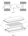
- a motor 40, a controller 30, and a battery 10 may be disposed inside the vehicle 1.
- the controller 30 is configured to control the battery 10 to supply power to the motor 40.
- the battery 10 may be disposed at the bottom, front, or rear of the vehicle 1.
- the battery 10 may be configured to supply power to the vehicle 1.
- the battery 10 may serve as an operating power supply of the vehicle 1 to power a circuit system of the vehicle 1.
- the battery may be configured to meet operating power usage requirements of the vehicle 1 that is being started or navigated or running.
- the battery 10 serves not only as an operating power supply of the vehicle 1, but may also serve as a driving power supply of the vehicle 1 to provide driving power for the vehicle 1 in place of or partly in place of fuel oil or natural gas.
- the battery 10 may also be referred to as a battery pack.
- the battery 10 may include a plurality of battery cells 20.
- the plurality of battery cells 20 may be connected in series, parallel, or series-and-parallel pattern.
- the series-and-parallel pattern means a combination of series connection and parallel connection.
- both the first box portion 111 and the second box portion 112 each may be a hollow cuboid, and each may include only one opening surface.
- the opening of the first box portion 111 is opposite to the opening of the second box portion 112.
- the first box portion 111 and the second box portion 112 are snap-fitted together to form a box 11 that includes a closed cavity.
- first box portion 111 and the second box portion 112 For another example, different from what is shown in FIG. 2 , of the first box portion 111 and the second box portion 112, only one is a hollow cuboid with an opening, and the other assumes a plate shape to cover the opening.
- the second box portion 112 is a hollow cuboid with one opening surface, and the first box portion 111 assumes a plate shape.
- the first box portion 111 fits and covers the opening of the second box portion 112 to form a box 11 with a closed cavity.
- the cavity may be configured to accommodate a plurality of battery cells 20.
- the plurality of battery cells 20 are combined and connected in parallel, series, or series-and-parallel pattern, and then placed into the box 11 that is formed by snap-fitting the first part 111 and the second part 112 together.
- the battery 10 may further include other structures, details of which are omitted here.
- the battery 10 may further include a busbar component.
- the busbar component is configured to implement electrical connection between the plurality of battery cells 20, such as parallel connection, series connection, or series-parallel connection.
- the busbar component may implement the electrical connection between the battery cells 20 by connecting electrode terminals of the battery cells 20.
- the busbar component may be fixed to the electrode terminals of the battery cells 20 by welding. Electrical energy of the plurality of battery cells 20 may be further led out by a conductive mechanism running through the box 11.
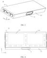
- FIG. 3 to FIG. 5 show a battery cell 20 according to an embodiment of this application.
- FIG. 4 is a schematic diagram of an internal pressure release path of the battery cell 20 shown in FIG. 3 ; and
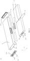
- FIG. 5 is a schematic exploded view of the battery cell 20 shown in FIG. 3 and FIG. 4 .
- the battery cell 20 includes a housing 21, a plurality of electrode assemblies 22, and a pressure relief mechanism 23.
- the plurality of electrode assemblies 22 are accommodated in the housing 21.
- the pressure relief mechanism 23 is disposed on a first wall 213 of the housing 21 and located at a position on the first wall 213, where the position is opposite to a region between two adjacent electrode assemblies 22 among the plurality of electrode assemblies 22.
- the pressure relief mechanism 23 is configured to release an internal pressure of the battery cell 20 when the internal pressure of the battery cell 20 exceeds a threshold.
- the number of electrode assemblies 22 included in a battery cell 20 is not particularly limited in an embodiment of in this application.
- the battery cell 20 may include two electrode assemblies 22.
- the two electrode assemblies 22 may be arranged along the length direction X of the battery cell 20.
- the battery cell 20 may include a plurality of pairs of electrode assemblies 22, and the plurality of pairs of electrode assemblies 22 may be arranged along a thickness direction Y of the battery cell 20.
- Each pair of the electrode assemblies 22 includes two electrode assemblies 22 arranged along the length direction X of the battery cell 20.
- the battery cell 20 may include more than two electrode assemblies 22, and the electrode assemblies 22 are arranged along the length direction X of the battery cell 20.
- the internal pressure of the battery cell exceeds a threshold, and the pressure relief mechanism 23 can be actuated when the internal pressure of the battery cell reaches the threshold, so as to form an internal pressure release path to release the internal pressure, reduce the risk of explosion of the battery cell 20, and improve the safety of the battery cell 20.
- the pressure relief mechanism 23 may be disposed at a position on the first wall 213, where the position is opposite to a region between the first electrode assembly 221 and the second electrode assembly 222 arranged along the length direction X.
- the arrow in FIG. 4 indicates the pressure release path.
- the pressure relief mechanism 23 is actuated, and the internal pressure is released outward from the battery cell 20 along the arrow direction to implement quick pressure relief.
- the two rectangular dashed line boxes in FIG. 4 represent the first electrode assembly 221 and the second electrode assembly 222 respectively.
- the shape of the battery cell 20 is not limited in this embodiment of this application.
- the battery cell 20 may be cuboidal, and includes electrode assemblies 22 arranged along the length direction X.
- the pressure relief mechanism 23 is located at a position on the first wall 213 of the housing 21, where the position is opposite to the region between two adjacent electrode assemblies arranged along the length direction X of the battery cell 20. In this way, when the internal pressure of the battery cell 20 exceeds a threshold, the pressure relief mechanism 23 forms an effective path for releasing the internal pressure, thereby solving the problem of difficulty to release the internal pressure of a long battery cell.
- an insulation strip 24 is disposed between the two adjacent electrode assemblies 22.
- an insulation strip 24 is disposed between the first electrode assembly 221 and the second electrode assembly 222 to reduce the possibility of contact between the first electrode assembly 221 and the second electrode assembly 222, reduce the risk of a short circuit, and improve the safety of the battery cell 20.
- two tabs of the electrode assembly 22 are disposed on a first end face 223 of the electrode assembly 22.
- the first end face 223 is perpendicular to the length direction X of the battery cell 20.
- a tab of one electrode assembly and a tab of the other electrode assembly are oriented in opposite directions and both oriented outward from the battery cell 20.
- the tab of one electrode assembly and the tab of the other electrode assembly are located on the two end faces of the battery cell 20 in the length direction X respectively, thereby making it convenient to connect the tabs to the electrode terminals 214 of the battery cell 20.
- the housing 21 includes a first opening 2211 and a second opening 2212 opposite to each other along the length direction X of the battery cell 20.
- the battery cell 20 further includes a first end cap 2121 and a second end cap 2122.
- the first end cap 2121 and the second end cap 2122 are configured to cover the first opening 2211 and the second opening 2212 respectively.
- the housing 21 of the battery cell 20 includes a first opening 2211 and a second opening 2212 opposite to each other along the length direction X of the battery cell 20, and the battery cell 20 further includes a first end cap 2121 and a second end cap 2122 that are configured to cover the first opening 2211 and the second opening 2212 respectively, thereby making it convenient to put the electrode assembly 22 into the housing and simplifying the assembling process of the battery cell 20.
- the two adjacent electrode assemblies 22 arranged along the length direction X of the battery cell 20 are insulated from each other.
- a positive electrode terminal and a negative electrode terminal of the battery cell 20 are disposed on the first end cap 2121, and configured to lead out electrical energy of one electrode assembly 22 among the two adjacent electrode assemblies 22.
- a positive electrode terminal and a negative electrode terminal of the battery cell 20 are disposed on the second end cap 2122, and configured to lead out electrical energy of the other electrode assembly 22 among the two adjacent electrode assemblies 22.
- the positive electrode terminal and the negative electrode terminal of the battery cell 20 are disposed on both the first end cap 2121 and the second end cap 2122. That is, a pair of electrode terminals is disposed on both the first end cap 2121 and the second end cap 2122, and the adjacent electrode assemblies 22 arranged along the length direction X of the battery cell 20 are insulated from each other. Therefore, the two pairs of electrode terminals can conduct the current of different electrode assemblies 22 respectively, thereby reducing the current flowing between the electrode assemblies 22, reducing the heat generated by the battery cell, and improving the charging and discharging performance of the battery cell 20.
- a pair of electrode terminals 214 of the battery cell 20 is disposed on the first end cap 2121, and includes a first electrode terminal 214a and a second electrode terminal 214b.
- a pair of electrode terminals 214 of the battery cell 20 is also disposed on the second end cap 2122, and includes a first electrode terminal 214a and a second electrode terminal 214b.
- the electrode terminals 214 on the second end cap 2122 are not shown in FIG. 5 .
- the first electrode terminal 214a and the second electrode terminal 214b one is a positive electrode terminal, and the other is a negative electrode terminal.
- the electrode terminal 214 on the first end cap 2121 and the electrode terminal 214 on the second end cap 2122 can conduct the current of the first electrode assembly 221 and the second electrode assembly 222 respectively, so as to reduce the current flowing between the first electrode assembly 221 and the second electrode assembly 222, reduce the heat generated by the battery cell 20, and improve the charging and discharging performance of the battery cell 20.
- the housing 21 further includes a partition plate 25, configured to cover the first wall 213 of the housing 21 to isolate surfaces of the plurality of electrode assemblies 22 from the housing 21.
- the first wall 213 of the housing 21 is a smaller-area wall of the housing 21.
- the first electrode assembly 221 and the second electrode assembly 222 expand in volume and squeeze the partition plate 25 that covers the first wall 23, thereby resulting in deformation of the partition plate 25, and in turn, causing deformation of the pressure relief mechanism 23.
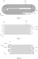
- the type of the electrode assembly 22 is not limited in this embodiment of this application.
- the electrode assembly 22 includes a first electrode plate 224 and a second electrode plate 225.
- the first electrode plate 224 and the second electrode plate 225 are wound around a winding axis.
- the winding axis is parallel to the length direction X of the battery cell 20.
- the electrode assembly 22 includes a plurality of first electrode plates 224 and a plurality of second electrode plates 225.
- the plurality of first electrode plates 224 and the plurality of second electrode plates 225 are stacked alternately along a second direction Y.
- the second direction Y is perpendicular to the length direction X of the battery cell 20.
- the electrode assembly 22 includes a first electrode plate 224 and a plurality of second electrode plates 225.
- the first electrode plate 224 includes a plurality of stacked sections 224a and a plurality of bent sections 224b. Each bent section 224b is configured to connect two adjacent stacked sections 224a.
- the plurality of second electrode plates 225 and the plurality of stacked sections 224a are stacked alternately along a second direction Y.
- the second direction Y is perpendicular to the length direction X of the electrode assembly 22.
- the winding axis of the first electrode plate 224 and the second electrode plate 225 of the electrode assembly 22 is parallel to the length direction X of the battery cell 20, or the stacking direction of the first electrode plate 224 and the second electrode plate 225 of the electrode assembly 22 is perpendicular to the length direction X of the battery cell. Therefore, most of the gas generated by the electrode assembly 22 is expelled from the end of the first electrode plate in the length direction X and the end of the second electrode plate in the length direction X. A gap for passing the gas is formed between the end of the first electrode plate 224 along the length direction X and the end of the second electrode plate 225 along the length direction X.
- the pressure relief mechanism 23 is located at a position on the first wall 213, where the position is opposite to the region between the first electrode assembly 221 and the second electrode assembly 222 arranged along the length direction.
- the gas can pass through the gap and act on the pressure relief mechanism 23 to actuate the pressure relief mechanism 23, so as to release the internal pressure.
- the electrode assembly 22 further includes a separator 226 configured to dielectrically isolate the first electrode plate 224 from the second electrode plate 225.
- the first wall 213 of the housing 21 is a bottom wall of the housing 21.
- the pressure relief mechanism 23 faces downward. In this way, when the battery 10 is mounted under the seat of a vehicle 1, the pressure relief mechanism 23 can be kept away from passengers. Therefore, the internal pressure of the battery cell 20 is released downward, thereby reducing the risk of injury to the passengers.
- this application further designs the thicknesses of the pressure relief mechanism 23 and the housing 21. A detailed description is given below with reference to FIG. 10 to FIG. 12 .
- FIG. 10 shows a first wall 213, and a pressure relief mechanism 23 is disposed on the first wall 213.
- FIG. 11 is a cross-sectional view of the battery cell 20 shown in FIG. 10 and sectioned along an A-A direction.
- FIG 12 is a close-up view of a local region B in the battery cell 20 shown in FIG. 11 .
- the thickness of the first wall 213 of the housing 21 is greater than the thickness of any other wall of the housing 21 other than the first wall 213.
- the thickness of the first wall 213 is greater than the thicknesses of the second wall 214, the third wall 215, and the fourth wall 216 of the housing 21 other than the first wall 213.
- the first wall 213 on which the pressure relief mechanism 23 is disposed is thicker than other walls of the housing 21 other than the first wall 213. The relatively thick first wall 213 improves the welding reliability of the pressure relief mechanism 23, and makes the first wall 213 not prone to deform.
- the pressure relief mechanism 23 is less affected by the creep caused by the internal pressure of the battery cell 20, and in turn, the burst pressure of the pressure relief mechanism 23 is less affected by the creep. Therefore, the pressure relief mechanism 23 can effectively release the internal pressure when the internal pressure is greater than the threshold. In addition, the decrease in the thickness of other walls also reduces the manufacturing cost of the housing 21.
- the thickness of the pressure relief mechanism 23 is less than the thickness of the housing 21.
- the thickness of the pressure relief mechanism 23 is a thickness at an effective position of the pressure relief mechanism 23.
- the effective position is a position to be burst open first on the pressure relief mechanism 23. In this way, by setting the thickness of the pressure relief mechanism 23 to be less than the thickness of the housing 21, the pressure relief mechanism 23 can be burst open first when the internal pressure of the battery cell 20 is greater than the threshold, thereby providing an effective pressure relief path.
- the thickness of the first wall 213 of the housing 21 is greater than the thicknesses of other walls of the housing 21 other than the first wall 213, and the thickness of the pressure relief mechanism 23 is less than the thicknesses of other walls of the housing 21 other than the first wall 213.
- the pressure relief mechanism 23 can be burst open first when the internal pressure of the battery cell 20 is greater than the threshold, thereby providing an effective pressure relief path.
- the thicker first wall 213 improves the welding reliability of the pressure relief mechanism 23 on the first wall 213, and makes the first wall 213 not prone to deform. In this way, the pressure relief mechanism 23 is less affected by the creep caused by the internal pressure, and in turn, the burst pressure of the pressure relief mechanism 23 is less affected by the creep. Therefore, the pressure relief mechanism 23 can effectively release the internal pressure when the internal pressure is greater than the threshold.
- the decrease in the thickness of other walls also reduces the manufacturing cost of the housing 21.
- the thickness of the pressure relief mechanism 23 is a thickness at an effective position of the pressure relief mechanism 23.
- the effective position is a position to be burst open first on the pressure relief mechanism 23.
- a nick 231 is created on the pressure relief mechanism 23, and the thickness of the pressure relief mechanism 23 is a residual thickness of the nick 231.
- the pressure relief mechanism 23 is burst open first by means of the nick 231.
- the nick makes the manufacturing process simple, and achieves a good pressure relief effect.
- the position of the nick 213 is the effective position of the pressure relief mechanism 23, and the thickness of the pressure relief mechanism 23 is the residual thickness of the nick 213.
- the battery cell 20 includes the housing 21 and two end caps.
- the housing 21 includes four walls.
- the thickness of the first wall 213 is greater than the thickness of any one of the other three walls.
- the housing 21 includes five walls.
- the thickness of the first wall 213 on which the pressure relief mechanism 23 is disposed may be greater than the thickness of any one of the other four walls.
- the form of the pressure relief mechanism 23 is not limited in an embodiment of this application.
- the pressure relief mechanism 23 may be a component that is relatively independent of the first wall 213. For example, an opening is created on the first wall 213, the pressure relief mechanism 23 covers the opening, and a nick 231 is created on the pressure relief mechanism 23; or, the pressure relief mechanism 23 is a nick 231 formed directly on the first wall 213.
- the pressure relief mechanism 23 is recessed in the first wall 213 of the housing 21, that is, buried in the first wall 213, thereby avoiding the impact caused by collision or other factors to the pressure relief mechanism 23 in a process of fitting the pressure relief mechanism 23 to the housing 21.
- the pressure relief mechanism 23 When the thickness of the pressure relief mechanism 23 is relatively large, the pressure relief mechanism may fail to be burst open first. When the thickness of the pressure relief mechanism 23 is relatively small, the assembling difficulty is increased, and the pressure relief mechanism is prone to be damaged during the assembling.
- the thickness of the pressure relief mechanism 23 needs to be set by considering the internal pressure of the battery cell 20, and usually needs to match the threshold and enable the pressure relief mechanism to be burst open first when the internal pressure of the battery cell exceeds the threshold. For example, in an embodiment, the thickness T0 of the pressure relief mechanism 23 is greater than or equal to 0.01 mm and less than or equal to 0.5 mm.
- a relatively large thickness of the first wall 213 brings additional cost.
- a relatively small thickness of the first wall makes the burst pressure of the pressure relief mechanism 23 be easily affected by the creep caused by the internal pressure of the battery cell 20. Therefore, the thickness of the first wall needs to set to a value within an appropriate range.
- the thickness T1 of the first wall is greater than or equal to 0.2 mm and less than or equal to 3 mm.
- the thickness of other walls of the housing 21 other than the first wall 213 brings additional cost, and a relatively small thickness of other walls of the housing other than the first wall is unable to ensure a sufficient structural stability of the battery cell 20. Therefore, the thickness of other walls also needs to be set to a value in an appropriate range.
- the thickness of any other wall of the housing 21 other than the first wall 213 is greater than or equal to 0.2 mm and less than or equal to 1 mm.
- the pressure relief mechanism 23 on the battery cell 20 is disposed on the first wall 213 of the housing 21.
- the first wall 213 is a bottom wall of the housing 21.
- the pressure relief mechanism 23 is located at a position on the first wall 213, where the position is opposite to a region between two adjacent electrode assemblies 22 arranged along the length direction X of the battery cell 20.
- a nick 231 is created on the pressure relief mechanism 23.
- the thickness of the first wall is greater than the thickness of any other wall of the housing other than the first wall, and the residual thickness of the nick 231 is less than the thickness of the housing 21.
- the pressure relief mechanism 23 on the battery cell 20 in an embodiment of this application is disposed on the first wall 213 of the housing 21, and is located at a position on the first wall 213, where the position is opposite to a region between two adjacent electrode assemblies 22.
- the internal pressure of the battery cell 20 reaches the threshold, the internal pressure release path formed by the pressure release mechanism 23 is relatively short, thereby facilitating the release of pressure, improving the performance of the pressure release mechanism 23, and improving the safety of the battery cell 20.
- Described above are the battery cell 20, battery 10, and electrical device 1 according to some embodiments of this application.
- the following describes a battery cell 20 manufacturing method and equipment according to some embodiments of this application. For the information not detailed in the following embodiments, reference may be made to the preceding embodiments.
- FIG. 13 is a schematic flowchart of a battery cell 20 manufacturing method 300 according to an embodiment of this application.
- the manufacturing method 300 includes: providing a housing 21 and a plurality of electrode assemblies 22, where a pressure relief mechanism 23 is disposed on a first wall 213 of the housing 21, and the pressure relief mechanism 23 is configured to release an internal pressure of the battery cell 20 when the internal pressure of the battery cell 20 exceeds a threshold; and letting the plurality of electrode assemblies 22 be accommodated in the housing 21 so that the pressure relief mechanism 23 is located at a position on the first wall 213, where the position is opposite to a region between two adjacent electrode assemblies 22 among the plurality of electrode assemblies 22.
- FIG. 14 is a schematic block diagram of battery cell 20 manufacturing equipment 400 according to an embodiment of this application.
- the equipment 400 includes: a providing module 410, configured to provide a housing 21 and a plurality of electrode assemblies, where a pressure relief mechanism 23 is disposed on a first wall 213 of the housing 21, and the pressure relief mechanism 23 is configured to release an internal pressure of the battery cell 20 when the internal pressure of the battery cell 2020 exceeds a threshold; and an assembling module 420, configured to let the plurality of electrode assemblies 22 be accommodated in the housing 21 so that the pressure relief mechanism 23 is located at a position on the first wall 213, where the position is opposite to a region between two adjacent electrode assemblies 22 among the plurality of electrode assemblies 22.
Landscapes
- Chemical & Material Sciences (AREA)
- Chemical Kinetics & Catalysis (AREA)
- Electrochemistry (AREA)
- General Chemical & Material Sciences (AREA)
- Engineering & Computer Science (AREA)
- Manufacturing & Machinery (AREA)
- Secondary Cells (AREA)
- Battery Mounting, Suspending (AREA)
- Connection Of Batteries Or Terminals (AREA)
Applications Claiming Priority (1)
| Application Number | Priority Date | Filing Date | Title |
|---|---|---|---|
| PCT/CN2022/081788 WO2023173428A1 (zh) | 2022-03-18 | 2022-03-18 | 电池单体及其制造方法和制造设备、电池、用电设备 |
Publications (2)
| Publication Number | Publication Date |
|---|---|
| EP4485657A1 true EP4485657A1 (de) | 2025-01-01 |
| EP4485657A4 EP4485657A4 (de) | 2025-08-20 |
Family
ID=88021980
Family Applications (1)
| Application Number | Title | Priority Date | Filing Date |
|---|---|---|---|
| EP22931459.6A Pending EP4485657A4 (de) | 2022-03-18 | 2022-03-18 | Batteriezelle und herstellungsverfahren und herstellungsvorrichtung dafür, batterie und stromverbrauchende vorrichtung |
Country Status (4)
| Country | Link |
|---|---|
| US (1) | US20240204341A1 (de) |
| EP (1) | EP4485657A4 (de) |
| CN (1) | CN222980706U (de) |
| WO (1) | WO2023173428A1 (de) |
Families Citing this family (1)
| Publication number | Priority date | Publication date | Assignee | Title |
|---|---|---|---|---|
| JP2025167462A (ja) * | 2024-04-26 | 2025-11-07 | プライムプラネットエナジー&ソリューションズ株式会社 | 電池およびその搭載構造 |
Family Cites Families (9)
| Publication number | Priority date | Publication date | Assignee | Title |
|---|---|---|---|---|
| JP4219661B2 (ja) * | 2002-11-22 | 2009-02-04 | パナソニック株式会社 | 電池用封口板 |
| JP5503101B2 (ja) * | 2007-06-22 | 2014-05-28 | 株式会社神戸製鋼所 | 電池ケース |
| US20130196194A1 (en) * | 2012-01-31 | 2013-08-01 | Samsung Sdi Co., Ltd. | Secondary battery |
| CN113169401B (zh) * | 2020-03-02 | 2023-11-21 | 东莞新能安科技有限公司 | 电池、电池模组、电池包、电动车、储能装置和电动工具 |
| CN213782158U (zh) * | 2020-07-10 | 2021-07-23 | 宁德时代新能源科技股份有限公司 | 电池、包括电池的装置和制备电池的设备 |
| CN213026310U (zh) * | 2020-07-10 | 2021-04-20 | 宁德时代新能源科技股份有限公司 | 电池盒、电池单体、电池和用电设备 |
| CN215771451U (zh) * | 2021-09-15 | 2022-02-08 | 合肥国轩高科动力能源有限公司 | 方形锂电子动力电池 |
| CN215989095U (zh) * | 2021-10-18 | 2022-03-08 | 河南省鹏辉电源有限公司 | 电芯壳体、电芯及电池模组 |
| CN114171805B (zh) * | 2021-12-03 | 2024-01-26 | 合肥国轩高科动力能源有限公司 | 一种锂离子电池结构及其装配方法 |
-
2022
- 2022-03-18 EP EP22931459.6A patent/EP4485657A4/de active Pending
- 2022-03-18 CN CN202290000656.1U patent/CN222980706U/zh active Active
- 2022-03-18 WO PCT/CN2022/081788 patent/WO2023173428A1/zh not_active Ceased
-
2024
- 2024-03-01 US US18/592,996 patent/US20240204341A1/en active Pending
Also Published As
| Publication number | Publication date |
|---|---|
| WO2023173428A1 (zh) | 2023-09-21 |
| EP4485657A4 (de) | 2025-08-20 |
| CN222980706U (zh) | 2025-06-13 |
| US20240204341A1 (en) | 2024-06-20 |
Similar Documents
| Publication | Publication Date | Title |
|---|---|---|
| EP4439838A1 (de) | Batteriezelle, batterie und elektrische vorrichtung | |
| EP4080661B1 (de) | Batteriezelle, batterie und energieverbrauchende vorrichtung | |
| EP4485660A1 (de) | Gehäuse, batteriezelle, batterie und elektrische vorrichtung | |
| EP4481930A1 (de) | Batterie und elektrische vorrichtung | |
| US20240283099A1 (en) | Battery cell, battery, power consumption device, and method and device for producing battery cell | |
| CN217788704U (zh) | 电池单体、电池和用电设备 | |
| CN115172979B (zh) | 电池模组、电池以及用电装置 | |
| US20230216154A1 (en) | Current collecting member, battery cell, battery, and power consuming device | |
| CN216250906U (zh) | 电池单体、电池和用电设备 | |
| US20230178860A1 (en) | Battery cell, battery, power consuming device, and method and apparatus for manufacturing battery cell | |
| US20230369711A1 (en) | End cap, battery cell, battery and power consuming device | |
| US20240304965A1 (en) | Battery cell, battery, electrical device, and method and equipment for manufacturing battery cell | |
| US20250079651A1 (en) | Battery Cell, Battery and Electrical Equipment | |
| US20230420798A1 (en) | Battery, electric apparatus, and method and apparatus for manufacturing battery | |
| EP4181281A1 (de) | Batterie, elektrische vorrichtung sowie verfahren und vorrichtung zur herstellung der batterie | |
| US20240204341A1 (en) | Battery cell, battery cell manufacturing method and equipment, battery, and electrical device | |
| CN217768626U (zh) | 电池单体、电池以及用电装置 | |
| EP4468485A1 (de) | Batteriezelle, batteriemodul, batterie und stromverbrauchende vorrichtung | |
| EP4425691A1 (de) | Batteriezelle, batterie und elektrische vorrichtung | |
| EP4184694A1 (de) | Batteriezelle, batterie, elektrische vorrichtung sowie verfahren und vorrichtung zur herstellung einer batteriezelle | |
| CN116941075B (zh) | 集流构件、电池单体、电池及用电设备 | |
| EP4447185A1 (de) | Elektrodenanordnung, batteriezelle, batterie und elektrische vorrichtung | |
| EP4550533A1 (de) | Batteriezelle, batterie und elektrische vorrichtung | |
| EP4343934A1 (de) | Batterie, elektrische vorrichtung sowie batterieherstellungsverfahren und -vorrichtung | |
| CN117063338A (zh) | 电池、用电设备、制备电池的方法和设备 |
Legal Events
| Date | Code | Title | Description |
|---|---|---|---|
| STAA | Information on the status of an ep patent application or granted ep patent |
Free format text: STATUS: THE INTERNATIONAL PUBLICATION HAS BEEN MADE |
|
| PUAI | Public reference made under article 153(3) epc to a published international application that has entered the european phase |
Free format text: ORIGINAL CODE: 0009012 |
|
| STAA | Information on the status of an ep patent application or granted ep patent |
Free format text: STATUS: REQUEST FOR EXAMINATION WAS MADE |
|
| 17P | Request for examination filed |
Effective date: 20240926 |
|
| AK | Designated contracting states |
Kind code of ref document: A1 Designated state(s): AL AT BE BG CH CY CZ DE DK EE ES FI FR GB GR HR HU IE IS IT LI LT LU LV MC MK MT NL NO PL PT RO RS SE SI SK SM TR |
|
| DAV | Request for validation of the european patent (deleted) | ||
| DAX | Request for extension of the european patent (deleted) | ||
| A4 | Supplementary search report drawn up and despatched |
Effective date: 20250717 |
|
| RIC1 | Information provided on ipc code assigned before grant |
Ipc: H01M 50/30 20210101AFI20250711BHEP Ipc: H01M 10/0583 20100101ALI20250711BHEP Ipc: H01M 50/548 20210101ALI20250711BHEP Ipc: H01M 10/0585 20100101ALI20250711BHEP Ipc: H01M 50/103 20210101ALI20250711BHEP Ipc: H01M 50/55 20210101ALI20250711BHEP Ipc: H01M 50/342 20210101ALI20250711BHEP Ipc: H01M 10/04 20060101ALI20250711BHEP Ipc: H01M 50/15 20210101ALI20250711BHEP Ipc: H01M 50/209 20210101ALI20250711BHEP Ipc: H01M 50/35 20210101ALI20250711BHEP |