EP4485691A1 - Dispositif électronique et ensemble dispositif électronique - Google Patents
Dispositif électronique et ensemble dispositif électronique Download PDFInfo
- Publication number
- EP4485691A1 EP4485691A1 EP23791077.3A EP23791077A EP4485691A1 EP 4485691 A1 EP4485691 A1 EP 4485691A1 EP 23791077 A EP23791077 A EP 23791077A EP 4485691 A1 EP4485691 A1 EP 4485691A1
- Authority
- EP
- European Patent Office
- Prior art keywords
- electronic device
- radiating element
- casing
- watch strap
- feeding unit
- Prior art date
- Legal status (The legal status is an assumption and is not a legal conclusion. Google has not performed a legal analysis and makes no representation as to the accuracy of the status listed.)
- Pending
Links
Images




Classifications
-
- H—ELECTRICITY
- H01—ELECTRIC ELEMENTS
- H01Q—ANTENNAS, i.e. RADIO AERIALS
- H01Q1/00—Details of, or arrangements associated with, antennas
- H01Q1/27—Adaptation for use in or on movable bodies
- H01Q1/273—Adaptation for carrying or wearing by persons or animals
-
- G—PHYSICS
- G04—HOROLOGY
- G04G—ELECTRONIC TIME-PIECES
- G04G17/00—Structural details; Housings
- G04G17/02—Component assemblies
- G04G17/04—Mounting of electronic components
-
- H—ELECTRICITY
- H01—ELECTRIC ELEMENTS
- H01Q—ANTENNAS, i.e. RADIO AERIALS
- H01Q1/00—Details of, or arrangements associated with, antennas
- H01Q1/50—Structural association of antennas with earthing switches, lead-in devices or lightning protectors
-
- H—ELECTRICITY
- H01—ELECTRIC ELEMENTS
- H01Q—ANTENNAS, i.e. RADIO AERIALS
- H01Q7/00—Loop antennas with a substantially uniform current distribution around the loop and having a directional radiation pattern in a plane perpendicular to the plane of the loop
-
- H—ELECTRICITY
- H01—ELECTRIC ELEMENTS
- H01Q—ANTENNAS, i.e. RADIO AERIALS
- H01Q9/00—Electrically-short antennas having dimensions not more than twice the operating wavelength and consisting of conductive active radiating elements
- H01Q9/04—Resonant antennas
- H01Q9/30—Resonant antennas with feed to end of elongated active element, e.g. unipole
-
- H—ELECTRICITY
- H01—ELECTRIC ELEMENTS
- H01Q—ANTENNAS, i.e. RADIO AERIALS
- H01Q9/00—Electrically-short antennas having dimensions not more than twice the operating wavelength and consisting of conductive active radiating elements
- H01Q9/04—Resonant antennas
- H01Q9/30—Resonant antennas with feed to end of elongated active element, e.g. unipole
- H01Q9/42—Resonant antennas with feed to end of elongated active element, e.g. unipole with folded element, the folded parts being spaced apart a small fraction of the operating wavelength
Definitions
- Embodiments of this application relate to the field of wearable device technologies, and in particular, to an electronic device and an electronic device assembly.
- Mainstream product forms include a watch type (for example, a watch, a band, or a wrist strap) supported by a wrist, a shoes type (for example, shoes, socks, or another product worn on legs in the future) supported by feet, and a glass type (for example, glasses, a helmet, or a headband) supported by head.
- Non-mainstream product forms include smart clothing, a schoolbag, a cane, an accessory, and the like.
- an antenna design usually requires an antenna clearance of at least 1 mm (which is usually a distance between an antenna and another metal component inside an entire device, for example, a distance between the antenna and a battery). With continuous evolution of competitiveness such as product miniaturization, the antenna clearance is further reduced.
- a size of a watch or a band in a wearing span direction is usually designed to be large.
- Embodiments of this application provide an electronic device and an electronic device assembly, so that a size of the electronic device can be reduced, and the entire electronic device is small. This can improve wearing experience of a user.
- an embodiment of this application provides an electronic device.
- the electronic device includes at least a casing and an antenna assembly. At least one outer side wall of the casing is provided with a first groove that is configured to connect at least the electronic device and an external component.
- a first receiving cavity is further provided inside the casing. At least a part of a radiating element of the antenna assembly is located in the first receiving cavity, and a projection of the first receiving cavity in a thickness direction of the electronic device at least partially overlaps with a projection of the first groove in the thickness direction of the electronic device.
- the at least one outer side wall of the casing is provided with the first groove that is configured to connect at least the electronic device and the external component.
- the first receiving cavity is further provided inside the casing.
- the projection of the first receiving cavity in the thickness direction of the electronic device at least partially overlaps with the projection of the first groove in the thickness direction of the electronic device.
- the first receiving cavity is configured to accommodate the at least the part of the radiating element of the antenna assembly. In this way, when a watch strap head grain is placed in the first groove, a projection of the watch strap head grain in the thickness direction of the electronic device overlaps with a projection of the at least the part of the radiating element of the antenna assembly in the thickness direction of the electronic device.
- locations of the watch strap head grain and the radiating element of the antenna assembly do not interfere with each other in a length direction or a width direction of the electronic device, and occupy a small space, so that a size of the electronic device can be reduced, and the entire electronic device is small. This can improve wearing experience of a user to some extent.
- the first receiving cavity is located in a space enclosed by a middle frame of the electronic device, a top wall of the first groove, an outer side wall that is of the casing and that is away from the middle frame, and a plane on which a display of the electronic device is located.
- the antenna assembly includes at least the radiating element and a feeding unit connected to the radiating element.
- the feeding unit is further connected to a circuit board of the electronic device.
- a part of the radiating element of the antenna assembly is located in the first receiving cavity, the feeding unit and the remaining part of the radiating element of the antenna assembly are located in an accommodating cavity formed between an outer side wall of a battery and an inner side wall of the casing, and the feeding unit is connected to a circuit board of the electronic device, so that a feeding function and radiation performance of the antenna assembly can be ensured.
- the antenna assembly further includes a radiating branch.
- One end of the radiating element is connected to one end of the radiating branch, the other end of the radiating element is connected to the feeding unit, and the other end of the radiating branch bends in a direction away from a surface of the radiating element, and extends toward an extension direction of the radiating element.
- the radiating branch is designed and added, and the radiating branch is connected to an end that is of the radiating element and that is away from the feeding unit, so that the radiating branch can perform a tuning function. For example, antenna resonance frequency tuning can be performed through a length change of the radiating branch. This improves radiation performance of the radiating element and increases an implementable function of the antenna assembly.
- the radiating element includes a main body portion and a bending support portion. One end of the main body portion is connected to the radiating branch, the other end of the main body portion is connected to one end of the bending support portion, and the other end of the bending support portion is connected to the feeding unit.
- the radiating element has a first side face and a second side face opposite to the first side face.
- One end of the radiating branch is connected to one end of the main body portion of the radiating element, and the other end of the radiating branch bends in a direction away from the second side face and extends toward the other end of the main body portion.
- One end of the feeding unit is connected to one end of the bending support portion of the radiating element, and the other end of the feeding unit extends in a direction perpendicular to a plane on which the bending support portion is located.
- the radiating element has a first side face and a second side face opposite to the first side face.
- One end of the radiating branch is connected to one end of the main body portion of the radiating element, and the other end of the radiating branch bends in a direction away from the first side face and extends toward the other end of the main body portion.
- One end of the feeding unit is connected to one end of the bending support portion of the radiating element, and the other end of the feeding unit extends in a direction perpendicular to a plane on which the bending support portion is located.
- the antenna assembly further includes a grounding unit.
- One end of the radiating element is connected to the grounding unit, and the other end of the radiating element is connected to the feeding unit.
- the grounding unit and the feeding unit are disposed opposite to each other.
- the grounding unit is disposed in the antenna assembly, and the grounding unit is connected to an end that is of the radiating element and that is away from the feeding unit.
- the grounding unit, the radiating element, and the feeding unit form a loop antenna, so that a tuning function can be implemented, radiation performance of the radiating element can be improved, and an implementable function of the antenna assembly can be increased.
- the radiating element is provided with a coupling gap.
- the coupling gap is disposed in a staggered manner relative to the grounding unit and the feeding unit.
- the radiating element is provided with the coupling gap, and the grounding unit, the feeding unit, and the radiating element having the coupling gap form a coupling loop antenna, so that a tuning function can be further performed, radiation performance of the radiating element can be further improved, and an implementable function of the antenna assembly can be further increased.
- the radiating element includes a main body portion and a bending support portion.
- One end of the main body portion is connected to the grounding unit, the other end of the main body portion is connected to one end of the bending support portion, and the other end of the bending support portion is connected to the feeding unit.
- one end of the main body portion is connected to the feeding unit, the other end of the main body portion is connected to one end of the bending support portion, and the other end of the bending support portion is connected to the grounding unit.
- the electronic device further includes a battery.
- the battery is located inside the casing.
- An accommodating cavity is formed between an outer side wall of the battery and an inner side wall of the casing.
- the accommodating cavity is configured to accommodate at least the feeding unit.
- the accommodating cavity communicates with the first receiving cavity to jointly accommodate the antenna assembly.
- the first receiving cavity communicates with the accommodating cavity formed between the outer side wall of the battery and the inner side wall of the casing.
- a distance between the battery and the radiating element is greater than 1 mm. A sufficient distance between the battery and the radiating element can ensure a clearance of the antenna.
- an embodiment of this application provides an electronic device assembly.
- the electronic device assembly includes at least a watch strap assembly and any one of the foregoing electronic devices.
- the watch strap assembly is connected to the electronic device by using the first groove.
- the electronic device assembly includes at least an electronic device.
- at least one outer side wall of a casing is provided with a first groove that is configured to connect at least the electronic device and an external component.
- a first receiving cavity is further provided inside the casing.
- a projection of the first receiving cavity in a thickness direction of the electronic device at least partially overlaps with a projection of the first groove in the thickness direction of the electronic device.
- the first receiving cavity is configured to accommodate at least a part of a radiating element of an antenna assembly.
- a projection of the watch strap head grain in the thickness direction of the electronic device overlaps with a projection of the at least the part of the radiating element of the antenna assembly in the thickness direction of the electronic device.
- locations of the watch strap head grain and the radiating element of the antenna assembly do not interfere with each other in a length direction or a width direction of the electronic device, and occupy a small space, so that a size of the electronic device can be reduced, and the entire electronic device is small. This can improve wearing experience of a user to some extent.
- the electronic device assembly further includes a watch strap assembly.
- the watch strap assembly includes a watch strap and a spring bar connected to the watch strap.
- the first groove is located at one end that is of the casing and that faces the watch strap, and the spring bar is located in the first groove to connect the casing and the watch strap assembly.
- a spring bar hole is provided on a side wall of the first groove of the electronic device. Two ends of the spring bar are located in the spring bar hole.
- the watch strap assembly further includes a watch strap head grain.
- the watch strap head grain is connected to the watch strap. At least a part of the watch strap head grain is located in the first groove.
- a through hole extending in a width direction of the casing is provided in the watch strap head grain, and the spring bar runs through the through hole to connect the casing and the watch strap assembly.
- the spring bar hole and the through hole are disposed opposite to each other.
- the electronic device may be a wearable electronic device, for example, an electronic device that can be worn on a human body or a life body, for example, a watch, a band, or a finger ring.
- a watch is used as a specific example for illustration. It may be understood that the watch does not limit a specific type of the electronic device.
- the watch shown in this embodiment of this application is shown by using a rectangular watch face as an example. It should be understood that a shape of the watch face of the watch may alternatively be a circle, an ellipse, a square, or another polygon.
- the rectangular watch face in this embodiment of this application is merely used as a specific example, and does not specifically limit the shape of the watch face.
- the wearable electronic device usually includes an electronic device body and a wearing component, and the electronic device body is connected to the wearing component, to facilitate wearing of the electronic device by a human body.
- the wearing component may be a wristband, a watch strap, or the like.
- the wearing component may alternatively be an annular buckle of a finger ring, an annular band of a neck strap, or the like.
- an electronic device body of a wearable electronic device usually integrates various functions such as making a call and playing music.
- an antenna may be disposed on the electronic device body, to transmit and receive a signal through the antenna.
- An antenna performance level of the wearable electronic device in an actual use scenario directly relates to actual user experience.
- an antenna design usually requires an antenna clearance of at least 1 mm.
- the antenna clearance is a distance between an antenna and a battery.
- a size of a watch or a band in a wearing span direction is usually designed to be large, to ensure a sufficient antenna clearance.
- the body width of the wearable electronic device is usually designed to be narrow, which leads to a great length of the entire device, to ensure that the body has a specific volume to accommodate various electronic components.
- an antenna structure is disposed inside a casing 110 of the electronic device body, and the antenna structure includes an antenna support 210 and a flexible printed circuit (Flexible Printed Circuit, FPC) antenna.
- the antenna support 210 is configured to fasten and support an FPC antenna 220.
- a watch strap connection mechanism 230 is disposed at an end that is of the wearing component and that is close to the casing 110. The watch strap connection mechanism 230 is configured to connect the casing 110 and the wearing component, to implement integral assembly of the wearable electronic device.
- the antenna support 210, the FPC antenna 220, and the watch strap connection mechanism 230 are arranged in a wearing span direction L1.
- a distance namely, a first clearance distance D1
- a size of the wearable electronic device in the wearing span direction L1 is large. Consequently, a length of the entire wearable electronic device is large. This affects wearing experience of a user.
- an embodiment of this application provides a new electronic device.
- the electronic device at least one outer side wall of a casing is provided with a first groove that is configured to connect at least the electronic device and an external component.
- a first receiving cavity is further provided inside the casing.
- a projection of the first receiving cavity in a thickness direction of the electronic device at least partially overlaps with a projection of the first groove in the thickness direction of the electronic device.
- the first receiving cavity is configured to accommodate at least a part of a radiating element of an antenna assembly.
- a projection of the watch strap head grain in the thickness direction of the electronic device overlaps with a projection of the at least the part of the radiating element of the antenna assembly in the thickness direction of the electronic device.
- locations of the watch strap head grain and the radiating element of the antenna assembly do not interfere with each other in a length direction or a width direction of the electronic device, and occupy a small space, so that a size of the electronic device can be reduced, and the entire electronic device is small. This can improve wearing experience of a user to some extent.
- the electronic device may include at least a casing 110 and an antenna assembly 140. At least one outer side wall of the casing 110 is provided with a first groove 111 that is configured to connect at least the electronic device and an external component (for example, a watch strap 121).
- a first receiving cavity 112 is further provided inside the casing 110. At least a part of a radiating element 141 of the antenna assembly 140 is located in the first receiving cavity 112, and a projection of the first receiving cavity 112 in a thickness direction of the electronic device at least partially overlaps with a projection of the first groove 111 in the thickness direction of the electronic device.
- the electronic device may further include a display 190, and the display 190 may cover an upper surface of the casing 110.
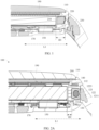
- the first receiving cavity 112 may be located above the first groove 111. Specifically, as shown in FIG. 2B or FIG. 3 , the first receiving cavity 112 may be located in a space enclosed by a middle frame 200, a top wall 1111 of the first groove, an outer side wall (namely, a first outer side wall 1101 of the casing) that is of the casing 110 and that is away from the middle frame 200, and a plane on which the display 190 is located.
- the casing 110 may be formed by injection molding.
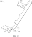
- the antenna assembly 140 may include at least a feeding unit 142 and the radiating element 141.
- the feeding unit 142 may be connected to a circuit board 170 of the electronic device (refer to FIG. 4 ).
- the radiating element 141 and the feeding unit are not located on a same plane. Specifically, a part of the radiating element 141 of the antenna assembly 140 is located in the first receiving cavity 112, the feeding unit 142 and the remaining part of the radiating element 141 of the antenna assembly 140 are located in an accommodating cavity 160 formed between an outer side wall of a battery 150 and an inner side wall of the casing 110, and the feeding unit 142 is connected to the circuit board 170 of the electronic device. This can ensure a feeding function and radiation performance of the antenna assembly 140.
- the feeding unit 142 may be connected to the circuit board 170 of the electronic device by using a spring 180 (refer to FIG. 4 ).
- a location of the feeding unit 142 disposed on the watch may be, for example, in a two o'clock direction, a ten o'clock direction, a four o'clock direction, or an eight o'clock direction. This is not limited in embodiments of this application.
- the antenna assembly 140 may be used in a Bluetooth antenna or a global positioning system (Global Positioning System, GPS) antenna.
- the antenna assembly 140 may be, for example, a monopole antenna, an inverted antenna, or a loop antenna.
- the antenna assembly 140 shown in FIG. 5 is a monopole antenna.
- the antenna assembly 140 may further include a radiating branch 143.
- One end of the radiating element 141 is connected to one end of the radiating branch 143, and the other end of the radiating element 141 is connected to the feeding unit 142; and the other end of the radiating branch 143 bends in a direction away from a surface of the radiating element 141, and extends toward an extension direction of the radiating element 141.
- the radiating branch 143 is designed and added, and the radiating branch 143 is connected to an end that is of the radiating element 141 and that is away from the feeding unit 142, so that the radiating branch 143 can perform a tuning function.
- antenna resonance frequency tuning can be performed through a length change of the radiating branch 143. This improves radiation performance of the radiating element 141 and increases an implementable function of the antenna assembly 140.
- the radiating element 141 includes a main body portion 1411 and a bending support portion 1412. One end of the main body portion 1411 is connected to the radiating branch 143, the other end of the main body portion 1411 is connected to one end of the bending support portion 1412, and the other end of the bending support portion 1412 is connected to the feeding unit 142.
- a plane on which the feeding unit 142 is located may be parallel with a plane on which the main body portion 1411 of the radiating element 141 is located.
- the feeding unit 142 and the main body portion 1411 are located at different heights in the casing 110.
- the radiating element 141 has a first side face 1411a and a second side face 1411b.
- the second side face 1411b is opposite to the first side face 1411a, and the radiating branch 143 is used as a bending radiation part.
- the antenna assembly 140 having the radiating branch 143 includes but is not limited to the following two possible implementations.
- the radiating branch 143 and the feeding unit 142 are located on different sides of the radiating element 141.
- one end of the radiating branch 143 is connected to one end of the main body portion 1411 of the radiating element 141, and the other end of the radiating branch 143 bends in a direction away from the second side face 1411b and extends toward the other end of the main body portion 1411.
- the radiating branch 143 is disposed close to the first side face 1411a of the radiating element 141.
- One end of the feeding unit 142 is connected to one end of the bending support portion 1412 of the radiating element 141, and the other end of the feeding unit 142 extends in a direction perpendicular to a plane on which the bending support portion 1412 is located.
- the radiating branch 143 and the feeding unit 142 are located on one side of the radiating element 141.
- one end of the radiating branch 143 is connected to one end of the main body portion 1411 of the radiating element 141, and the other end of the radiating branch 143 bends in a direction away from the first side face 1411a and extends toward the other end of the main body portion 1411.
- the radiating branch 143 is disposed close to the second side face 1411b of the radiating element 141.
- One end of the feeding unit 142 is connected to one end of the bending support portion 1412 of the radiating element 141, and the other end of the feeding unit 142 extends in a direction perpendicular to a plane on which the bending support portion 1412 is located.
- both the radiating branch 143 and the feeding unit 142 are located on the second side face 1411b of the radiating element 141.
- both the radiating branch 143 and the feeding unit 142 may be located on the first side face 1411a of the radiating element 141.
- the radiating branch 143 may be further added to any location in the middle of the radiating element 141 in the antenna assembly 140.
- the antenna assembly 140 may further include a grounding unit 144.
- One end of the radiating element 141 is connected to the grounding unit 144, and the other end of the radiating element 141 is connected to the feeding unit 142.
- the grounding unit 144 and the feeding unit 142 are disposed opposite to each other.
- the grounding unit 144 is disposed in the antenna assembly 140, and the grounding unit 144 is connected to an end that is of the radiating element 141 and that is away from the feeding unit 142.
- the grounding unit 144, the radiating element 141, and the feeding unit 142 form a loop antenna, so that a tuning function can be implemented, radiation performance of the radiating element 141 can be improved, and an implementable function of the antenna assembly 140 can be increased.
- the radiating element 141 may include a main body portion 1411 and a bending support portion 1412. One end of the main body portion 1411 is connected to the grounding unit 144, the other end of the main body portion 1411 is connected to one end of the bending support portion 1412, and the other end of the bending support portion 1412 is connected to the feeding unit 142.
- one end of the main body portion 1411 may be connected to the feeding unit 142, the other end of the main body portion 1411 may be connected to one end of the bending support portion 1412, and the other end of the bending support portion 1412 may be connected to the grounding unit 144.
- the radiating element 141 may be provided with a coupling gap 1413.
- the coupling gap 1413 is disposed in a staggered manner relative to the grounding unit 144 and the feeding unit 142.
- the radiating element 141 is provided with the coupling gap 1413, and the grounding unit 144, the feeding unit 142, and the radiating element 141 having the coupling gap 1413 form a coupling loop antenna, so that a tuning function can be further performed, radiation performance of the radiating element 141 can be further improved, and an implementable function of the antenna assembly 140 can be further increased.
- a location of the feeding unit 142 disposed on the watch may be, for example, in a one o'clock direction, an eleven o'clock direction, a five o'clock direction, or a seven o'clock direction. This is not limited in embodiments of this application.
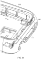
- the antenna assembly 140 in the electronic device provided in this embodiment of this application is an insert antenna.
- the antenna assembly 140 is embedded in the first receiving cavity 112 and the accommodating cavity 160 formed between the outer side wall of the battery 150 and the inner side wall of the casing 110.
- the antenna assembly 140 may be formed by using a conductive metal.
- the antenna assembly 140 may be formed by using a steel sheet, a copper material, or another conductive material.
- the antenna assembly 140 is inserted into the casing 110 through insert injection molding or other techniques.
- the electronic device may further include a battery 150.
- the battery 150 is located inside the casing 110.
- An accommodating cavity 160 is formed between an outer side wall of the battery 150 and an inner side wall of the casing 110.
- the accommodating cavity 160 is configured to accommodate at least the feeding unit 142.
- the accommodating cavity 160 communicates with the first receiving cavity 112 to jointly accommodate the antenna assembly 140.
- the first receiving cavity 112 communicates with the accommodating cavity 160 formed between the outer side wall of the battery 150 and the inner side wall of the casing 110.
- the radiating element 141 of the antenna assembly 140 is located in the first receiving cavity 112, and other parts of the antenna assembly 140 than the radiating element 141 are located in the accommodating cavity 160 formed between the outer side wall of the battery 150 and the inner side wall of the casing 110. This ensures that the antenna assembly 140 is placed inside the casing 110.
- a distance (namely, a second clearance distance D2) between the battery 150 and the radiating element 141 may be greater than 1 mm. A sufficient distance between the battery 150 and the radiating element 141 can ensure a clearance of the antenna.
- the distance between the battery 150 and the radiating element 141 may be 1 mm, 1.5 mm, 2 mm, 2.5 mm, 3 mm, 3.5 mm, 4 mm, or the like. This is not limited in embodiments of this application, and is not limited to the foregoing example.
- an embodiment of this application further provides an electronic device assembly.
- the electronic device assembly may include at least a watch strap assembly 120 and the foregoing electronic device.
- the watch strap assembly 120 is connected to the electronic device.
- the watch strap assembly 120 may include a watch strap 121 and a watch strap head grain 122.
- the watch strap 121 is connected to the watch strap head grain 122.
- a second groove 1211 is provided at an end that is of the watch strap 121 and that faces the casing 110, and the watch strap head grain 122 is located in the second groove 1211 of the watch strap 121 and is connected to the watch strap 121.
- the first groove 111 is located at an end that is on the casing 110 and that faces the watch strap 121. At least a part of the watch strap head grain 122 is located in the first groove 111, and the watch strap head grain 122 is connected to the casing 110 by using the first groove 111. Specifically, when the watch strap assembly 120 is connected to the casing 110, the first groove 111 and the second groove 1211 are spliced to jointly form a second receiving cavity 130. In addition, the watch strap head grain 122 is located in the second receiving cavity 130. A projection of the second receiving cavity 130 in a thickness direction of the wearable electronic device 100 at least partially overlaps with a projection of the first receiving cavity 112 in the thickness direction of the wearable electronic device 100.
- a projection of the watch strap head grain 122 in the thickness direction of the wearable electronic device 100 overlaps with a projection of the at least the part of the radiating element 141 of the antenna assembly 140 in the thickness direction of the wearable electronic device 100.
- locations of the watch strap head grain 122 and the radiating element 141 of the antenna assembly 140 do not interfere with each other in a wearing span direction L1 of the wearable electronic device 100, and occupy a small space. Therefore, a stacking design of the antenna assembly 140, the casing 110, and the watch strap head grain 122 can ensure the antenna clearance and satisfy an antenna indicator.
- a size of the wearable electronic device 100 in the wearing span direction L1 is minimized, so that an overall length of the wearable electronic device 100 is small. This can improve wearing experience of the user to some extent.
- a shape of the watch strap head grain 122 may be a square, a circle, an irregular shape, or any other combination shape. This is not limited in embodiments of this application.
- shapes of the first groove 111 and the second groove 1211 adapt to the shape of the watch strap head grain 122.
- the shapes of the first groove 111 and the second groove 1211 may be squares, circles, irregular shapes, or any other combination shapes. This is not limited in embodiments of this application.
- a sufficient antenna clearance can be ensured, and a wearing span size of the wearable electronic device 100 can be reduced by more than 4 mm.
- the wearing span size of the wearable electronic device 100 is a distance between outer edges of two watch strap head grains 122 at two ends of the wearable electronic device 100 along the wearing span direction L1.
- the antenna assembly 140 may be disposed on at least one side of two sides of the watch strap assembly 120.
- the antenna assembly 140 may be disposed on the watch in a twelve o'clock direction or a six o'clock direction along the wearing span direction L1. This is not limited in embodiments of this application.
- the watch strap assembly 120 may further include a spring bar 123, and the spring bar 123 is located in the first groove 111.
- a through hole 1223 (as shown in FIG. 7 ) extending in a width direction of the casing 110 may be provided in the watch strap head grain 122, and the spring bar 123 may run through the through hole 1223 to connect the casing 110 and the watch strap assembly 120.
- the spring bar 123 fits with the watch strap head grain 122, and can connect the casing 110 and the watch strap assembly 120.
- the watch strap head grain 122 may include a first part 1221 and a second part 1222.
- the first part 1221 is fastened to the second part 1222.
- the first part 1221 may be located in the first groove 111 of the casing 110, and a shape of the first part 1221 adapts to a shape of the first groove 111.
- the second part 1222 may be located in the second groove 1211 of the watch strap 121, and a shape of the second part 1222 adapts to a shape of the second groove 1211.
- the spring bar 123 is a connecting piece for fastening the watch strap 121 and the watch face (namely, the casing 110).
- the spring bar 123 may be a steel rod.
- a spring bar hole 131 may be provided at a location that is on a side wall of the first groove 111 and that is opposite to the through hole 1223. Two ends of the spring bar 123 are located in the spring bar hole 131.
- the watch strap head grain 122 may be formed by using plastic, stainless steel, or another functional material.
- the spring bar 123 may include but is not limited to a single flange spring bar or a double flange spring bar. If a detaching function is not considered, the spring bar 123 may be a common spring bar.
- the watch strap assembly 120 may not include the watch strap head grain 122.
- the watch strap assembly 120 may include a watch strap 121 and a spring bar 123.
- the watch strap 121 may be directly connected to the casing 110 by using the spring bar 123.
- a through hole (not shown in the figure) that can be passed through by the spring bar 123 may be provided at an end that is of the watch strap 121 and that faces the casing 110.
- the spring bar 123 runs through the through hole, and two ends of the spring bar 123 are located in the spring bar hole 131 on the first groove 111, to implement connection between the watch strap 121 and the casing 110.
- the watch strap assembly 120 may further include more other components.
- a structure and composition of the watch strap assembly 120 are not limited in embodiments of this application.
- an orthographic projection of the first receiving cavity 112 in a thickness direction of the casing 110 may be located in the second receiving cavity 130.
- a space occupied by the first receiving cavity 112 and the second receiving cavity 130 in the wearing span direction L1 of the wearable electronic device 100 equals to a space occupied by the second receiving cavity 130 in the wearing span direction L1 of the wearable electronic device 100.
- Extra spaces in the wearing span direction L1 of the wearable electronic device 100 are not occupied, so that a size of the wearable electronic device 100 in the wearing span direction L1 can be greatly reduced.
- connection may be fastening, may be an indirect connection by using an intermediate medium, or may be an internal connection between two elements or an interaction relationship between two elements. Persons of ordinary skill in the art may understand specific meanings of the foregoing terms in embodiments of this application based on a specific situation.
Landscapes
- Physics & Mathematics (AREA)
- General Physics & Mathematics (AREA)
- Electric Clocks (AREA)
Applications Claiming Priority (2)
| Application Number | Priority Date | Filing Date | Title |
|---|---|---|---|
| CN202220901039.0U CN217768748U (zh) | 2022-04-19 | 2022-04-19 | 一种电子设备及电子设备组件 |
| PCT/CN2023/087503 WO2023202422A1 (fr) | 2022-04-19 | 2023-04-11 | Dispositif électronique et ensemble dispositif électronique |
Publications (2)
| Publication Number | Publication Date |
|---|---|
| EP4485691A1 true EP4485691A1 (fr) | 2025-01-01 |
| EP4485691A4 EP4485691A4 (fr) | 2025-06-25 |
Family
ID=83881141
Family Applications (1)
| Application Number | Title | Priority Date | Filing Date |
|---|---|---|---|
| EP23791077.3A Pending EP4485691A4 (fr) | 2022-04-19 | 2023-04-11 | Dispositif électronique et ensemble dispositif électronique |
Country Status (4)
| Country | Link |
|---|---|
| US (1) | US20250046986A1 (fr) |
| EP (1) | EP4485691A4 (fr) |
| CN (1) | CN217768748U (fr) |
| WO (1) | WO2023202422A1 (fr) |
Families Citing this family (2)
| Publication number | Priority date | Publication date | Assignee | Title |
|---|---|---|---|---|
| CN119447794B (zh) * | 2023-07-31 | 2025-11-11 | 北京小米移动软件有限公司 | 天线及电子设备 |
| CN118281544A (zh) * | 2024-05-10 | 2024-07-02 | 深圳疆泰科技有限公司 | 天线装置及其制备方法、智能腕表 |
Family Cites Families (17)
| Publication number | Priority date | Publication date | Assignee | Title |
|---|---|---|---|---|
| US5742256A (en) * | 1993-05-07 | 1998-04-21 | Seiko Epson Corporation | Wristband having embedded electrically conductive members for a wrist-mountable type electronic device |
| KR101622606B1 (ko) * | 2009-07-15 | 2016-05-20 | 엘지전자 주식회사 | 와치형 휴대 단말기 |
| EP2579107B1 (fr) * | 2011-10-05 | 2020-09-02 | Suunto Oy | Boîtier de montre et dispositif de montre-bracelet |
| CN203490475U (zh) * | 2013-09-06 | 2014-03-19 | 深圳市云家端关爱科技有限公司 | 智能手表表壳及智能手表 |
| JP6277665B2 (ja) * | 2013-10-22 | 2018-02-14 | セイコーエプソン株式会社 | 携帯機器 |
| US9703272B2 (en) * | 2014-06-25 | 2017-07-11 | Google Technology Holdings LLC | Apparatus with radiating element isolated from an electrically conductive wearable apparatus carrier device |
| KR102300862B1 (ko) * | 2014-09-15 | 2021-09-13 | 삼성전자주식회사 | 전자 장치 |
| US9985341B2 (en) * | 2015-08-31 | 2018-05-29 | Microsoft Technology Licensing, Llc | Device antenna for multiband communication |
| US9948006B2 (en) * | 2015-12-22 | 2018-04-17 | Cheng Uei Precision Industry Co., Ltd. | Antenna assembly and electronic device including the same |
| US10276925B2 (en) * | 2017-03-29 | 2019-04-30 | Garmin Switzerland Gmbh | Watch with slot antenna configuration |
| TWI637558B (zh) * | 2017-05-25 | 2018-10-01 | 和碩聯合科技股份有限公司 | 天線結構及電子裝置 |
| US10271299B1 (en) * | 2018-01-05 | 2019-04-23 | Garmin Switzerland Gmbh | Conductive watch housing with slot antenna configuration |
| CN210156587U (zh) * | 2019-07-11 | 2020-03-17 | Oppo广东移动通信有限公司 | 电子设备和可穿戴设备 |
| CN113497331B (zh) * | 2020-04-03 | 2023-03-10 | Oppo广东移动通信有限公司 | 电子设备及可穿戴设备 |
| CN111916887A (zh) * | 2020-08-18 | 2020-11-10 | 安徽华米信息科技有限公司 | 可穿戴设备及其天线加工方法 |
| US11658404B2 (en) * | 2020-09-22 | 2023-05-23 | Apple Inc. | Electronic devices having housing-integrated dielectric resonator antennas |
| CN215497061U (zh) * | 2021-09-28 | 2022-01-11 | 维沃移动通信有限公司 | 可穿戴设备 |
-
2022
- 2022-04-19 CN CN202220901039.0U patent/CN217768748U/zh active Active
-
2023
- 2023-04-11 WO PCT/CN2023/087503 patent/WO2023202422A1/fr not_active Ceased
- 2023-04-11 EP EP23791077.3A patent/EP4485691A4/fr active Pending
-
2024
- 2024-10-18 US US18/920,712 patent/US20250046986A1/en active Pending
Also Published As
| Publication number | Publication date |
|---|---|
| US20250046986A1 (en) | 2025-02-06 |
| EP4485691A4 (fr) | 2025-06-25 |
| CN217768748U (zh) | 2022-11-08 |
| WO2023202422A1 (fr) | 2023-10-26 |
Similar Documents
| Publication | Publication Date | Title |
|---|---|---|
| US20250046986A1 (en) | Electronic device and electronic device assembly | |
| US9196952B2 (en) | Multipurpose antenna | |
| US9703272B2 (en) | Apparatus with radiating element isolated from an electrically conductive wearable apparatus carrier device | |
| CN104319478B (zh) | 用于便携式终端的天线设备及具有天线设备的便携式终端 | |
| CN106711584B (zh) | 天线模组及具有该天线模组的穿戴式电子装置 | |
| US20120056792A1 (en) | Wearable device with antenna | |
| CN107846234A (zh) | 具有槽天线的无线通信装置 | |
| US11444371B2 (en) | Antenna for wearable devices | |
| WO1995027928A1 (fr) | Antenne pour appareil electronique portable | |
| US20210149347A1 (en) | Hybrid watch patch-antenna | |
| US10289159B2 (en) | Electronic device including antenna | |
| CN109244637A (zh) | 一种适用于全频段网络的金属环手表天线及金属环手表 | |
| US12381309B2 (en) | Antenna mounted on wearable device | |
| CN108023164B (zh) | 天线模组及具有该天线模组的穿戴式电子装置 | |
| US20040222930A1 (en) | Wrist antenna | |
| KR20120111094A (ko) | 플랙시블 인쇄회로기판을 이용한 착용식 모바일 디스플레이장치 | |
| JP2000105285A (ja) | 携帯型電子時計のアンテナ構造 | |
| CN107464984B (zh) | 芯片型天线及具备此的电子设备 | |
| CN106684554B (zh) | 穿戴式电子装置 | |
| TWI552441B (zh) | 在腕戴式無線設備中用於製作多頻帶天線的方法以及用於多頻帶天線的設備 | |
| US11647320B2 (en) | Elastomer sleeve for wireless earphone and wireless earphone | |
| TWI913630B (zh) | 穿戴式裝置 | |
| CN111293419A (zh) | 紧凑型lte天线布置 | |
| JPH06338819A (ja) | 腕装着型アンテナ装置およびこのアンテナ装置を備えた無線機 | |
| CN112886243B (zh) | 穿戴式电子设备 |
Legal Events
| Date | Code | Title | Description |
|---|---|---|---|
| STAA | Information on the status of an ep patent application or granted ep patent |
Free format text: STATUS: THE INTERNATIONAL PUBLICATION HAS BEEN MADE |
|
| PUAI | Public reference made under article 153(3) epc to a published international application that has entered the european phase |
Free format text: ORIGINAL CODE: 0009012 |
|
| STAA | Information on the status of an ep patent application or granted ep patent |
Free format text: STATUS: REQUEST FOR EXAMINATION WAS MADE |
|
| 17P | Request for examination filed |
Effective date: 20240924 |
|
| AK | Designated contracting states |
Kind code of ref document: A1 Designated state(s): AL AT BE BG CH CY CZ DE DK EE ES FI FR GB GR HR HU IE IS IT LI LT LU LV MC ME MK MT NL NO PL PT RO RS SE SI SK SM TR |
|
| REG | Reference to a national code |
Ref country code: DE Ref legal event code: R079 Free format text: PREVIOUS MAIN CLASS: H01Q0001360000 Ipc: H01Q0001270000 |
|
| A4 | Supplementary search report drawn up and despatched |
Effective date: 20250526 |
|
| RIC1 | Information provided on ipc code assigned before grant |
Ipc: H01Q 9/30 20060101ALI20250520BHEP Ipc: H01Q 9/42 20060101ALI20250520BHEP Ipc: H01Q 7/00 20060101ALI20250520BHEP Ipc: H01Q 1/27 20060101AFI20250520BHEP |
|
| DAV | Request for validation of the european patent (deleted) | ||
| DAX | Request for extension of the european patent (deleted) |