EP4485835A1 - Procédé et dispositif permettant d'effectuer une transmission de liaison montante dans un système de communication sans fil - Google Patents
Procédé et dispositif permettant d'effectuer une transmission de liaison montante dans un système de communication sans fil Download PDFInfo
- Publication number
- EP4485835A1 EP4485835A1 EP24212759.5A EP24212759A EP4485835A1 EP 4485835 A1 EP4485835 A1 EP 4485835A1 EP 24212759 A EP24212759 A EP 24212759A EP 4485835 A1 EP4485835 A1 EP 4485835A1
- Authority
- EP
- European Patent Office
- Prior art keywords
- transmission
- base station
- resource
- channel access
- uplink transmission
- Prior art date
- Legal status (The legal status is an assumption and is not a legal conclusion. Google has not performed a legal analysis and makes no representation as to the accuracy of the status listed.)
- Pending
Links
Images




Classifications
-
- H—ELECTRICITY
- H04—ELECTRIC COMMUNICATION TECHNIQUE
- H04L—TRANSMISSION OF DIGITAL INFORMATION, e.g. TELEGRAPHIC COMMUNICATION
- H04L5/00—Arrangements affording multiple use of the transmission path
- H04L5/003—Arrangements for allocating sub-channels of the transmission path
- H04L5/0044—Allocation of payload; Allocation of data channels, e.g. PDSCH or PUSCH
-
- H—ELECTRICITY
- H04—ELECTRIC COMMUNICATION TECHNIQUE
- H04L—TRANSMISSION OF DIGITAL INFORMATION, e.g. TELEGRAPHIC COMMUNICATION
- H04L5/00—Arrangements affording multiple use of the transmission path
- H04L5/003—Arrangements for allocating sub-channels of the transmission path
- H04L5/0058—Allocation criteria
- H04L5/0062—Avoidance of ingress interference, e.g. ham radio channels
-
- H—ELECTRICITY
- H04—ELECTRIC COMMUNICATION TECHNIQUE
- H04W—WIRELESS COMMUNICATION NETWORKS
- H04W24/00—Supervisory, monitoring or testing arrangements
- H04W24/08—Testing, supervising or monitoring using real traffic
-
- H—ELECTRICITY
- H04—ELECTRIC COMMUNICATION TECHNIQUE
- H04W—WIRELESS COMMUNICATION NETWORKS
- H04W72/00—Local resource management
- H04W72/04—Wireless resource allocation
- H04W72/044—Wireless resource allocation based on the type of the allocated resource
- H04W72/0446—Resources in time domain, e.g. slots or frames
-
- H—ELECTRICITY
- H04—ELECTRIC COMMUNICATION TECHNIQUE
- H04W—WIRELESS COMMUNICATION NETWORKS
- H04W72/00—Local resource management
- H04W72/04—Wireless resource allocation
- H04W72/044—Wireless resource allocation based on the type of the allocated resource
- H04W72/0453—Resources in frequency domain, e.g. a carrier in FDMA
-
- H—ELECTRICITY
- H04—ELECTRIC COMMUNICATION TECHNIQUE
- H04W—WIRELESS COMMUNICATION NETWORKS
- H04W72/00—Local resource management
- H04W72/12—Wireless traffic scheduling
- H04W72/1263—Mapping of traffic onto schedule, e.g. scheduled allocation or multiplexing of flows
- H04W72/1268—Mapping of traffic onto schedule, e.g. scheduled allocation or multiplexing of flows of uplink data flows
-
- H—ELECTRICITY
- H04—ELECTRIC COMMUNICATION TECHNIQUE
- H04W—WIRELESS COMMUNICATION NETWORKS
- H04W72/00—Local resource management
- H04W72/20—Control channels or signalling for resource management
- H04W72/21—Control channels or signalling for resource management in the uplink direction of a wireless link, i.e. towards the network
-
- H—ELECTRICITY
- H04—ELECTRIC COMMUNICATION TECHNIQUE
- H04W—WIRELESS COMMUNICATION NETWORKS
- H04W72/00—Local resource management
- H04W72/20—Control channels or signalling for resource management
- H04W72/23—Control channels or signalling for resource management in the downlink direction of a wireless link, i.e. towards a terminal
-
- H—ELECTRICITY
- H04—ELECTRIC COMMUNICATION TECHNIQUE
- H04W—WIRELESS COMMUNICATION NETWORKS
- H04W72/00—Local resource management
- H04W72/50—Allocation or scheduling criteria for wireless resources
- H04W72/53—Allocation or scheduling criteria for wireless resources based on regulatory allocation policies
-
- H—ELECTRICITY
- H04—ELECTRIC COMMUNICATION TECHNIQUE
- H04W—WIRELESS COMMUNICATION NETWORKS
- H04W72/00—Local resource management
- H04W72/50—Allocation or scheduling criteria for wireless resources
- H04W72/535—Allocation or scheduling criteria for wireless resources based on resource usage policies
-
- H—ELECTRICITY
- H04—ELECTRIC COMMUNICATION TECHNIQUE
- H04W—WIRELESS COMMUNICATION NETWORKS
- H04W72/00—Local resource management
- H04W72/50—Allocation or scheduling criteria for wireless resources
- H04W72/56—Allocation or scheduling criteria for wireless resources based on priority criteria
-
- H—ELECTRICITY
- H04—ELECTRIC COMMUNICATION TECHNIQUE
- H04W—WIRELESS COMMUNICATION NETWORKS
- H04W74/00—Wireless channel access
- H04W74/08—Non-scheduled access, e.g. ALOHA
- H04W74/0808—Non-scheduled access, e.g. ALOHA using carrier sensing, e.g. carrier sense multiple access [CSMA]
-
- H—ELECTRICITY
- H04—ELECTRIC COMMUNICATION TECHNIQUE
- H04W—WIRELESS COMMUNICATION NETWORKS
- H04W74/00—Wireless channel access
- H04W74/08—Non-scheduled access, e.g. ALOHA
- H04W74/0866—Non-scheduled access, e.g. ALOHA using a dedicated channel for access
- H04W74/0875—Non-scheduled access, e.g. ALOHA using a dedicated channel for access with assigned priorities based access
-
- H—ELECTRICITY
- H04—ELECTRIC COMMUNICATION TECHNIQUE
- H04L—TRANSMISSION OF DIGITAL INFORMATION, e.g. TELEGRAPHIC COMMUNICATION
- H04L27/00—Modulated-carrier systems
- H04L27/26—Systems using multi-frequency codes
- H04L27/2601—Multicarrier modulation systems
- H04L27/2602—Signal structure
- H04L27/26025—Numerology, i.e. varying one or more of symbol duration, subcarrier spacing, Fourier transform size, sampling rate or down-clocking
-
- H—ELECTRICITY
- H04—ELECTRIC COMMUNICATION TECHNIQUE
- H04W—WIRELESS COMMUNICATION NETWORKS
- H04W74/00—Wireless channel access
- H04W74/08—Non-scheduled access, e.g. ALOHA
- H04W74/0833—Random access procedures, e.g. with 4-step access
Definitions
- the present specification relates to a wireless communication system, particularly to a method and device for performing uplink/downlink transmission.
- 5G communication systems After commercialization of 4th generation (4G) communication system, in order to meet the increasing demand for wireless data traffic, efforts are being made to develop new 5th generation (5G) communication systems.
- the 5G communication system is called as a beyond 4G network communication system, a post LTE system, or a new radio (NR) system.
- 5G communication systems include systems operated using the millimeter wave (mmWave) band of 6 GHz or more, and include a communication system operated using a frequency band of 6 GHz or less in terms of ensuring coverage so that implementations in base stations and terminals are under consideration.
- mmWave millimeter wave
- a 3rd generation partnership project (3GPP) NR system enhances spectral efficiency of a network and enables a communication provider to provide more data and voice services over a given bandwidth. Accordingly, the 3GPP NR system is designed to meet the demands for high-speed data and media transmission in addition to supports for large volumes of voice.
- the advantages of the NR system are to have a higher throughput and a lower latency in an identical platform, support for frequency division duplex (FDD) and time division duplex (TDD), and a low operation cost with an enhanced end-user environment and a simple architecture.
- dynamic TDD of the NR system may use a method for varying the number of orthogonal frequency division multiplexing (OFDM) symbols that may be used in an uplink and downlink according to data traffic directions of cell users. For example, when the downlink traffic of the cell is larger than the uplink traffic, the base station may allocate a plurality of downlink OFDM symbols to a slot (or subframe). Information about the slot configuration should be transmitted to the terminals.
- OFDM orthogonal frequency division multiplexing
- cloud RAN cloud radio access network
- D2D device to device communication
- V2X vehicle to everything communication
- NTN non-terrestrial network communication
- CoMP coordinated multi-points
- FQAM FSK and QAM modulation
- SWSC sliding window superposition coding
- ACM advanced coding modulation
- FBMC filter bank multi-carrier
- NOMA non-orthogonal multiple access
- SCMA sparse code multiple access
- IoT Internet of Things
- IoE Internet of Everything
- sensing technology wired/wireless communication and network infrastructure, service interface technology, and security technology
- M2M machine to machine
- MTC machine type communication
- IoT environment an intelligent internet technology (IT) service that collects and analyzes data generated from connected objects to create new value in human life can be provided.
- IT internet technology
- 5G communication system to the IoT network.
- technologies such as a sensor network, a machine to machine (M2M), and a machine type communication (MTC) are implemented by techniques such as beamforming, MIMO, and array antennas.
- M2M machine to machine
- MTC machine type communication
- the application of the cloud RAN as the big data processing technology described above is an example of the fusion of 5G technology and IoT technology.
- a mobile communication system has been developed to provide voice service while ensuring the user's activity.
- the mobile communication system is gradually expanding not only the voice but also the data service, and now it has developed to the extent of providing high-speed data service.
- a more advanced mobile communication system is required due to a shortage phenomenon of resources and a high-speed service demand of users.
- an unlicensed frequency spectrum or an unlicensed frequency band e.g., 2.4 GHz band, 5 GHz band or higher band, or the like
- an unlicensed frequency band e.g., 2.4 GHz band, 5 GHz band or higher band, or the like
- unlicensed bands Unlike in licensed bands in which telecommunications carriers secure exclusive use rights through procedures such as auctions, in unlicensed bands, multiple communication devices may be used simultaneously without restrictions on the condition that only a certain level of adjacent band protection regulations are observed. For this reason, when an unlicensed band is used for cellular communication service, it is difficult to guarantee the communication quality to the level provided in the licensed band, and it is likely that interference with existing wireless communication devices (e.g., wireless LAN devices) using the unlicensed band occurs.
- existing wireless communication devices e.g., wireless LAN devices
- An object of the present specification is to provide a method for performing uplink/downlink transmission according to sharing of channel occupancy initiated by a user equipment in a wireless communication system.
- the present specification provides a method for receiving downlink transmission in a wireless communication system.
- a method performed by a user equipment includes: performing, to a base station, uplink transmission related to channel occupancy shared between the base station and the user equipment; and receiving, from the base station, downlink transmission performed by the base station after a gap from a time of reception of the uplink transmission, wherein the downlink transmission is performed based on channel access performed by the base station, the channel access is performed based on the gap, and information included in the downlink transmission and a resource on which the downlink transmission is performed are determined based on whether the user equipment has received, from the base station, a configuration of a threshold of energy detection for the channel occupancy.
- the channel access is channel access that allows the downlink transmission to be performed without performing channel sensing
- the gap when the gap is 16 ⁇ s, the gap includes one sensing slot within last 9 ⁇ s, and the channel access is channel access that allows the downlink transmission to be performed when the sensing slot is idle
- the gap when the gap is 25 ⁇ s, the gap is configured with a first interval of a length of 16 ⁇ s including a first sensing slot of a length of 9 ⁇ s and a second interval of a length of 9 ⁇ s that is a second sensing slot
- the channel access is channel access that allows the downlink transmission to be performed when the first sensing slot and the second sensing slot are idle.
- the information included in the downlink transmission includes at least one of unicast transmission for the user equipment or non-unicast transmission.
- the information included in the downlink transmission excludes unicast transmission, and a maximum number of symbols of a resource on which the downlink transmission is performed within the channel occupancy interval is any one of 2, 4, and 8.
- the uplink transmission is configured grant (CG)-physical uplink shared channel (PUSCH) performed on a resource pre-configured semi-statically from the base station.
- CG configured grant
- PUSCH physical uplink shared channel
- the method further includes, when the user equipment receives, from the base station, the configuration of the threshold of energy detection for the channel occupancy, receiving, from the base station, a configuration of information about a table including values set for each of one or more parameters for the channel occupancy and one or more indices corresponding to the set values, wherein the CG-PUSCH includes CG-uplink control information (UCI) including information indicating a first index among the one or more indices, and the downlink transmission is performed based on the values set for each of the one or more parameters corresponding to the first index.
- UCI CG-uplink control information
- the one or more parameters include at least one of channel access priority (CAPC), duration, or offset, wherein the CAPC is one used in the channel occupancy, the duration is the number of slots in which the downlink transmission is performed, and the offset is a difference from an end of a slot in which the base station detects the CG-UCI to a slot in which the downlink transmission is started.
- CAPC channel access priority
- duration is the number of slots in which the downlink transmission is performed
- offset is a difference from an end of a slot in which the base station detects the CG-UCI to a slot in which the downlink transmission is started.
- the method further includes, when the user equipment does not receive the configuration of the threshold of energy detection for the channel occupancy from the base station, receiving, from the base station, an offset for indicating a resource that is available for the downlink transmission, wherein the CG-PUSCH includes CG-UCI including information indicating that the channel occupancy is possible, and the downlink transmission is performed on resources between a last resource of a slot in which the base station detects the CG-UCI and a resource spaced apart therefrom by as much as the offset.
- the information included in the downlink transmission excludes unicast transmission, and a maximum number of symbols of the resource on which the downlink transmission is performed within the channel occupancy interval is any one of 2, 4, and 8.
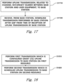
- a method for performing uplink transmission in a wireless communication system which is performed by a user equipment, includes: performing first transmission that is configured grant (CG) uplink transmission to a base station on a first resource, wherein the CG uplink transmission is transmission performed on a resource pre-configured semi-statically from the base station; and performing second transmission that is scheduled uplink transmission to the base station on a second resource, wherein the first resource and the second resource are continuous to each other in a time domain, when at least one pre-configured condition is satisfied, the second transmission is performed on the second resource immediately after a last symbol of the first resource, and when the at least one pre-configured condition is not satisfied, the first transmission is dropped at the last symbol of the first resource.
- CG configured grant
- One of the at least one pre-configured condition is a condition that the first transmission be performed based on channel access in which random backoff is performed using a contention window (CW) of a variable size.
- CW contention window
- One of the at least one pre-configured condition is a condition that when a bandwidth part (BWP) that is a resource in a frequency domain allocated for the first transmission is configured with a plurality of listen before talk (LBT) bandwidth subsets, a resource allocated for the second transmission occupy all resource blocks (RBs) included in at least one of the plurality of LBT bandwidth subsets.
- BWP bandwidth part
- LBT listen before talk
- One of the at least one pre-configured condition is a condition that a sum of a time domain of the first resource and a time domain of the second resource not exceed a maximum channel occupancy time (MCOT) corresponding to the first CAPC value.
- MCOT maximum channel occupancy time
- a user equipment for receiving downlink transmission in a wireless communication system includes: a communication module; and a processor that controls the communication module, wherein the processor performs uplink transmission to a base station, the uplink transmission being related to channel occupancy shared between the base station and the user equipment, and receives, from the base station, downlink transmission performed by the base station after a gap from a time of reception of the uplink transmission by the base station, wherein the downlink transmission is performed based on channel access performed by the base station, the channel access is performed based on the gap, and information included in the downlink transmission and a resource on which the downlink transmission is performed are determined based on whether the user equipment receives a configuration of a threshold of energy detection for the channel occupancy from the base station.
- the information included in the downlink transmission includes at least one of unicast transmission for the user equipment or non-unicast transmission, and when the user equipment does not receive, the configuration of the threshold of energy detection for the channel occupancy from the base station, the information included in the downlink transmission excludes unicast transmission, and a maximum number of symbols of a resource on which the downlink transmission is performed within the channel occupancy interval is any one of 2, 4, and 8.
- the present specification provides a method for performing a channel access procedure based on a gap for downlink transmission when an occupied channel initiated by a user equipment is shared in a wireless communication system, and thus downlink transmission can be performed efficiently.
- the present specification provides a method for performing uplink transmission when an occupied channel initiated by a user equipment is shared in a wireless communication system, and thus uplink transmission can be performed efficiently.
- the following technology may be used in various wireless access systems, such as code division multiple access (CDMA), frequency division multiple access (FDMA), time division multiple access (TDMA), orthogonal frequency division multiple access (OFDMA), single carrier-FDMA (SC-FDMA), and the like.
- CDMA may be implemented by a wireless technology such as universal terrestrial radio access (UTRA) or CDMA2000.
- the TDMA may be implemented by a wireless technology such as global system for mobile communications (GSM)/general packet radio service (GPRS)/enhanced data rates for GSM evolution (EDGE).
- GSM global system for mobile communications
- GPRS general packet radio service
- EDGE enhanced data rates for GSM evolution
- the OFDMA may be implemented by a wireless technology such as IEEE 802.11(Wi-Fi), IEEE 802.16(WiMAX), IEEE 802-20, evolved UTRA (E-UTRA), and the like.
- the UTRA is a part of a universal mobile telecommunication system (UMTS).
- 3rd generation partnership project (3GPP) long term evolution (LTE) is a part of an evolved UMTS (E-UMTS) using evolved-UMTS terrestrial radio access (E-UTRA) and LTE-advanced (A) is an evolved version of the 3GPP LTE.
- 3GPP new radio (NR) is a system designed separately from LTE/LTE-A, and is a system for supporting enhanced mobile broadband (eMBB), ultra-reliable and low latency communication (URLLC), and massive machine type communication (mMTC) services, which are requirements of IMT-2020.
- eMBB enhanced mobile broadband
- URLLC ultra-reliable and low latency communication
- mMTC massive machine type communication
- a base station may include a next generation node B (gNB) defined in 3GPP NR.
- the terminal may include user equipment (UE).
- gNB next generation node B
- UE user equipment
- the configuration of the terminal may indicate configuration by the base station. Specifically, the base station may transmit a channel or signal to the terminal to set an operation of the terminal or a parameter value used in a wireless communication system.
- FIG. 1 illustrates an example of a wireless frame structure used in a wireless communication system.
- the wireless frame (or radio frame) used in the 3GPP NR system may have a length of 10 ms ( ⁇ f max N f / 100) * T c ).
- the wireless frame includes 10 subframes (SFs) having equal sizes.
- ⁇ f max 480*10 3 Hz
- N f 4096
- T c 1/( ⁇ f re f*N f,ref )
- ⁇ f ref 15*10 3 Hz
- N f,ref 2048.
- Numbers from 0 to 9 may be respectively allocated to 10 subframes within one wireless frame.
- Each subframe has a length of 1 ms and may include one or more slots according to a subcarrier spacing.
- One subframe having a length of 1 ms may include 2 ⁇ slots. In this case, the length of each slot is 2 - ⁇ ms. Numbers from 0 to 2 ⁇ -1 may be respectively allocated to 2 ⁇ slots within one wireless frame. In addition, numbers from 0 to 10*2 ⁇ -1 may be respectively allocated to slots within one subframe.
- the time resource may be distinguished by at least one of a wireless frame number (also referred to as a wireless frame index), a subframe number (also referred to as a subframe index), and a slot number (or a slot index).
- FIG. 2 illustrates an example of a downlink (DL)/uplink (UL) slot structure in a wireless communication system.
- FIG. 2 shows the structure of the resource grid of the 3GPP NR system.
- a slot includes a plurality of orthogonal frequency division multiplexing (OFDM) symbols in a time domain and includes a plurality of resource blocks (RBs) in a frequency domain.
- An OFDM symbol also means one symbol section. Unless otherwise specified, OFDM symbols may be referred to simply as symbols.
- One RB includes 12 consecutive subcarriers in the frequency domain.
- a signal transmitted from each slot may be represented by a resource grid including N size, ⁇ grid,x * N RB sc subcarriers, and N slot symb OFDM symbols.
- N size, ⁇ grid,x represents the number of resource blocks (RBs) according to the subcarrier spacing constituent ⁇ (x is DL or UL), and N slot symb represents the number of OFDM symbols in a slot.
- An OFDM symbol may be referred to as a cyclic shift OFDM (CP-OFDM) symbol or a discrete Fourier transform spread OFDM (DFT-s-OFDM) symbol according to a multiple access scheme.
- the number of OFDM symbols included in one slot may vary according to the length of a cyclic prefix (CP). For example, in the case of a normal CP, one slot includes 14 OFDM symbols, but in the case of an extended CP, one slot may include 12 OFDM symbols. In a specific embodiment, the extended CP can only be used at 60 kHz subcarrier spacing.
- one slot is configured with 14 OFDM symbols by way of example, but embodiments of the present disclosure may be applied in a similar manner to a slot having a different number of OFDM symbols.
- each OFDM symbol includes N size, ⁇ grid,x * N RB sc subcarriers in the frequency domain.
- the type of subcarrier may be divided into a data subcarrier for data transmission, a reference signal subcarrier for transmission of a reference signal, and a guard band.
- the carrier frequency is also referred to as the center frequency (fc).
- One RB may be defined by N RB sc (e. g., 12) consecutive subcarriers in the frequency domain.
- N RB sc e. g., 12
- a resource configured with one OFDM symbol and one subcarrier may be referred to as a resource element (RE) or a tone. Therefore, one RB can be configured with N slot symb * N RB sc resource elements.
- Each resource element in the resource grid can be uniquely defined by a pair of indexes (k, l) in one slot.
- k may be an index assigned from 0 to N size, ⁇ grid, x * N RB sc - 1 in the frequency domain
- l may be an index assigned from 0 to N slot symb - 1 in the time domain.
- the time/frequency of the UE may be synchronized with the time/frequency of the base station. This is because when the base station and the UE are synchronized, the UE can determine the time and frequency parameters necessary for demodulating the DL signal and transmitting the UL signal at the correct time.
- Each symbol of a radio frame used in a time division duplex (TDD) or an unpaired spectrum may be configured with at least one of a DL symbol, an UL symbol, and a flexible symbol.
- a radio frame used as a DL carrier in a frequency division duplex (FDD) or a paired spectrum may be configured with a DL symbol or a flexible symbol
- a radio frame used as a UL carrier may be configured with a UL symbol or a flexible symbol.
- FDD frequency division duplex
- a radio frame used as a UL carrier may be configured with a UL symbol or a flexible symbol.
- DL symbol DL transmission is possible, but UL transmission is impossible.
- UL transmission In the UL symbol, UL transmission is possible, but DL transmission is impossible.
- the flexible symbol may be determined to be used as a DL or an UL according to a signal.
- Information on the type of each symbol i.e., information representing any one of DL symbols, UL symbols, and flexible symbols, may be configured with a cell-specific or common radio resource control (RRC) signal.
- RRC radio resource control
- information on the type of each symbol may additionally be configured with a UE-specific or dedicated RRC signal.
- the base station informs, by using cell-specific RRC signals, i) the period of cell-specific slot configuration, ii) the number of slots with only DL symbols from the beginning of the period of cell-specific slot configuration, iii) the number of DL symbols from the first symbol of the slot immediately following the slot with only DL symbols, iv) the number of slots with only UL symbols from the end of the period of cell specific slot configuration, and v) the number of UL symbols from the last symbol of the slot immediately before the slot with only the UL symbol.
- symbols not configured with any one of a UL symbol and a DL symbol are flexible symbols.
- the base station may signal whether the flexible symbol is a DL symbol or an UL symbol in the cell-specific RRC signal.
- the UE-specific RRC signal can not change a DL symbol or a UL symbol configured with the cell-specific RRC signal into another symbol type.
- the UE-specific RRC signal may signal the number of DL symbols among the N slot symb symbols of the corresponding slot for each slot, and the number of UL symbols among the N slot symb symbols of the corresponding slot.
- the DL symbol of the slot may be continuously configured with the first symbol to the i-th symbol of the slot.
- the UL symbol of the slot may be continuously configured with the j-th symbol to the last symbol of the slot (where i ⁇ j).
- symbols not configured with any one of a UL symbol and a DL symbol are flexible symbols.
- the type of symbol configured with the above RRC signal may be referred to as a semi-static DL/UL configuration.
- the flexible symbol may be indicated as a DL symbol, an UL symbol, or a flexible symbol through dynamic slot format information (SFI) transmitted on a physical DL control channel (PDCCH).
- SFI slot format information
- PDCCH physical DL control channel
- Table 1 exemplifies the dynamic SFI that the base station can indicate to the UE.
- D denotes a DL symbol
- U denotes a UL symbol
- X denotes a flexible symbol.
- up to two DL/UL switching in one slot may be allowed.
- FIG. 3 is a diagram for explaining a physical channel used in a 3GPP system (e.g., NR) and a typical signal transmission method using the physical channel.
- a 3GPP system e.g., NR
- the UE performs an initial cell search (step S101). Specifically, the UE may synchronize with the BS in the initial cell search. For this, the UE may receive a primary synchronization signal (PSS) and a secondary synchronization signal (SSS) from the base station to synchronize with the base station, and obtain information such as a cell ID. Thereafter, the UE can receive the physical broadcast channel from the base station and obtain the broadcast information in the cell.
- PSS primary synchronization signal
- SSS secondary synchronization signal
- the UE may perform a random access procedure on the base station (steps S103 to S106).
- the UE can transmit a preamble through a physical random access channel (PRACH) (step S103) and receive a response message for the preamble from the base station through the PDCCH and the corresponding PDSCH (step S104).
- PRACH physical random access channel
- the UE transmits data including the identifier of the UE and the like to the base station through a physical uplink shared channel (PUSCH) indicated by the UL grant transmitted through the PDCCH from the base station (step S105).
- PUSCH physical uplink shared channel
- the CQI, PMI, and R777I may be included in channel state information (CSI).
- the UE may transmit control information such as HARQ-ACK and CSI described above through the PUSCH and/or PUCCH.
- the UE may obtain time and frequency synchronization with the cell and perform an initial cell search procedure.
- the UE may detect a physical cell identity N cell ID of the cell during a cell search procedure.
- the UE may receive a synchronization signal, for example, a primary synchronization signal (PSS) and a secondary synchronization signal (SSS), from a base station, and synchronize with the base station.
- PSS primary synchronization signal
- SSS secondary synchronization signal
- the UE can obtain information such as a cell identity (ID).
- ID cell identity
- the synchronization signal can be classified into PSS and SSS.
- the PSS may be used to obtain time domain synchronization and/or frequency domain synchronization, such as OFDM symbol synchronization and slot synchronization.
- the SSS can be used to obtain frame synchronization and cell group ID.
- the PSS is transmitted in the first OFDM symbol and the SSS is transmitted in the third OFDM symbol through the 56th to 182th subcarriers.
- the lowest subcarrier index of the SS/PBCH block is numbered from 0.
- the base station does not transmit a signal through the remaining subcarriers, i.e., 0th to 55th and 183th to 239th subcarriers.
- the base station does not transmit a signal through 48th to 55th and 183th to 191th subcarriers.
- the base station transmits a physical broadcast channel (PBCH) through the remaining RE except for the above signal in the SS/PBCH block.
- PBCH physical broadcast channel
- Table 2 Channel or signal OFDM symbol number l relative to the start of an SS/PBCH block
- Subcarrier number k relative to the start of an SS/PBCH block PSS 0 56, 57, ..., 182 SSS 2 56, 57, ..., 182 Set to 0 0 0, 1, ..., 55, 183, 184, ..., 239 2 48, 49, ..., 55, 183, 184, ..., 191 PBCH 1, 3 0, 1, ..., 239 2 0, 1, ..., 47, 192, 193, ..., 239 DM-RS for PBCH 1, 3 0+ ⁇ ,4+ ⁇ ,8+ ⁇ ,...,236+ ⁇ 2 0+ ⁇ 4+ ⁇ ,8+ ⁇ ,....44+ ⁇ 192+ ⁇ ,196+ ⁇ ,...236+ ⁇ ⁇
- the UE may detect the PSS and identify one of the three unique physical-layer identifiers.
- the UE can detect the SSS and identify one of the 336 physical layer cell IDs associated with the physical-layer identifier.
- sequence dsss(n) of the SSS is as follows.
- a radio frame with a 10 ms length may be divided into two half frames with a 5 ms length.
- a slot in which the SS/PBCH block is transmitted may be any one of the cases A, B, C, D, and E.
- the subcarrier spacing is 15 kHz and the starting time point of the SS/PBCH block is the ( ⁇ 2, 8 ⁇ + 14*n)-th symbol.
- n 0 or 1 at a carrier frequency of 3 GHz or less.
- the subcarrier spacing is 30 kHz and the starting time point of the SS/PBCH block is ⁇ 4, 8, 16, 20 ⁇ + 28*n.
- n 0 at a carrier frequency of 3 GHz or less.
- it may be n 0, 1 at carrier frequencies above 3 GHz and below 6 GHz.
- the subcarrier spacing is 30 kHz and the starting time point of the SS/PBCH block is the ( ⁇ 2, 8 ⁇ + 14*n)-th symbol.
- n 0 or 1 at a carrier frequency of 3 GHz or less.
- it may be n 0, 1, 2, 3 at carrier frequencies above 3 GHz and below 6 GHz.
- FIG. 5 illustrates a procedure for transmitting control information and a control channel in a 3GPP NR system.
- the base station may add a cyclic redundancy check (CRC) masked (e.g., an XOR operation) with a radio network temporary identifier (RNTI) to control information (e.g., downlink control information (DCI)) (step S202).
- CRC cyclic redundancy check
- RNTI radio network temporary identifier
- the base station may scramble the CRC with an RNTI value determined according to the purpose/target of each control information.
- the common RNTI used by one or more UEs can include at least one of a system information RNTI (SI-RNTI), a paging RNTI (P-RNTI), a random access RNTI (RA-RNTI), and a transmit power control RNTI (TPC-RNTI).
- SI-RNTI system information RNTI
- P-RNTI paging RNTI
- RA-RNTI random access RNTI
- TPC-RNTI transmit power control RNTI
- the UE-specific RNTI may include at least one of a cell temporary RNTI (C-RNTI), and the CS-RNTI.
- the base station may perform ratematching (step S206) according to the amount of resource(s) used for PDCCH transmission after performing channel encoding (e.g., polar coding) (step S204).
- channel encoding e.g., polar coding
- the number of CCEs used for one PDCCH may be defined as an aggregation level.
- an aggregation level of 1, 2, 4, 8, or 16 may be used.
- FIG. 5(b) is a diagram related to a CCE aggregation level and the multiplexing of a PDCCH and illustrates the type of a CCE aggregation level used for one PDCCH and CCE(s) transmitted in the control area according thereto.
- the CORESET is a time-frequency resource in which PDCCH, that is, a control signal for the UE, is transmitted.
- PDCCH that is, a control signal for the UE
- a search space to be described later may be mapped to one CORESET. Therefore, the UE may monitor the time-frequency domain designated as CORESET instead of monitoring all frequency bands for PDCCH reception, and decode the PDCCH mapped to CORESET.
- the base station may configure one or more CORESETs for each cell to the UE.
- the CORESET may be configured with up to three consecutive symbols on the time axis.
- the CORESET may be configured in units of six consecutive PRBs on the frequency axis. In the embodiment of FIG.
- CORESET#1 is configured with consecutive PRBs
- CORESET#2 and CORESET#3 are configured with discontinuous PRBs.
- the CORESET can be located in any symbol in the slot. For example, in the embodiment of FIG. 5 , CORESET#1 starts at the first symbol of the slot, CORESET#2 starts at the fifth symbol of the slot, and CORESET#9 starts at the ninth symbol of the slot.
- FIG. 7 illustrates a method for setting a PDCCH search space in a 3GPP NR system.
- each CORESET may have at least one search space.
- the search space is a set of all time-frequency resources (hereinafter, PDCCH candidates) through which the PDCCH of the UE is capable of being transmitted.
- the search space may include a common search space that the UE of the 3GPP NR is required to commonly search and a UE-specific or a UE-specific search space that a specific UE is required to search.
- UE may monitor the PDCCH that is set so that all UEs in the cell belonging to the same base station commonly search.
- the UE-specific search space may be set for each UE so that UEs monitor the PDCCH allocated to each UE at different search space position according to the UE.
- the search space between the UEs may be partially overlapped and allocated due to the limited control area in which the PDCCH may be allocated.
- Monitoring the PDCCH includes blind decoding for PDCCH candidates in the search space. When the blind decoding is successful, it may be expressed that the PDCCH is (successfully) detected/received and when the blind decoding fails, it may be expressed that the PDCCH is not detected/not received, or is not successfully detected/received.
- a PDCCH scrambled with a group common (GC) RNTI previously known to one or more UEs so as to transmit DL control information to the one or more UEs is referred to as a group common (GC) PDCCH or a common PDCCH.
- a PDCCH scrambled with a specific-terminal RNTI that a specific UE already knows so as to transmit UL scheduling information or DL scheduling information to the specific UE is referred to as a specific-UE PDCCH.
- the common PDCCH may be included in a common search space, and the UE-specific PDCCH may be included in a common search space or a UE-specific PDCCH.
- the base station may signal each UE or UE group through a PDCCH about information (i.e., DL Grant) related to resource allocation of a paging channel (PCH) and a downlink-shared channel (DL-SCH) that are a transmission channel or information (i.e., UL grant) related to resource allocation of a uplink-shared channel (UL-SCH) and a hybrid automatic repeat request (HARQ).
- the base station may transmit the PCH transport block and the DL-SCH transport block through the PDSCH.
- the base station may transmit data excluding specific control information or specific service data through the PDSCH.
- the UE may receive data excluding specific control information or specific service data through the PDSCH.
- the base station may include, in the PDCCH, information on to which UE (one or a plurality of UEs) PDSCH data is transmitted and how the PDSCH data is to be received and decoded by the corresponding UE, and transmit the PDCCH.
- the DCI transmitted on a specific PDCCH is CRC masked with an RNTI of "A”
- the DCI indicates that PDSCH is allocated to a radio resource (e.g., frequency location) of "B” and indicates transmission format information (e.g., transport block size, modulation scheme, coding information, etc.) of "C”.
- the UE monitors the PDCCH using the RNTI information that the UE has.
- the UE receives the PDCCH, and receives the PDSCH indicated by "B" and "C" through the received PDCCH information.
- Table 3 shows an embodiment of a physical uplink control channel (PUCCH) used in a wireless communication system.
- PUCCH physical uplink control channel
- the PUCCH may be used to transmit the following UL control information (UCI).
- UCI UL control information
- five PUCCH formats may be used to support various service scenarios, various channel environments, and frame structures.
- PUCCH format 0 is a format capable of delivering 1-bit or 2-bit HARQ-ACK information or SR.
- PUCCH format 0 can be transmitted through one or two OFDM symbols on the time axis and one PRB on the frequency axis.
- the sequence may be a sequence cyclic shifted (CS) from a base sequence used in PUCCH format 0.
- CS cyclic shift
- the UE may obtain a frequency diversity gain.
- the base sequence having the length of 12 may be transmitted by mapping a cyclic shifted sequence based on a predetermined CS value m cs to one OFDM symbol and 12 REs of one RB.
- M bit 1 bit UCI 0 and 1 may be mapped to two cyclic shifted sequences having a difference of 6 in the cyclic shift value, respectively.
- M bit 2 bit UCI 00, 01, 11, and 10 may be mapped to four cyclic shifted sequences having a difference of 3 in cyclic shift values, respectively.
- PUCCH format 1 may deliver 1-bit or 2-bit HARQ-ACK information or SR.
- PUCCH format 1 maybe transmitted through consecutive OFDM symbols on the time axis and one PRB on the frequency axis.
- the number of OFDM symbols occupied by PUCCH format 1 may be one of 4 to 14.
- QPSK quadrature phase shift keying
- a signal is obtained by multiplying a modulated complex valued symbol d(0) by a sequence of length 12.
- the sequence may be a base sequence used for PUCCH format 0.
- the UE spreads the even-numbered OFDM symbols to which PUCCH format 1 is allocated through the time axis orthogonal cover code (OCC) to transmit the obtained signal.
- PUCCH format 1 determines the maximum number of different UEs multiplexed in the one RB according to the length of the OCC to be used.
- a demodulation reference signal (DMRS) may be spread with OCC and mapped to the oddnumbered OFDM symbols of PUCCH format 1.
- PUCCH format 2 may deliver UCI exceeding 2 bits.
- PUCCH format 2 may be transmitted through one or two OFDM symbols on the time axis and one or a plurality of RBs on the frequency axis.
- the sequences which are transmitted in different RBs through the two OFDM symbols may be same each other.
- the sequence may be a plurality of modulated complex valued symbols d(0),..., d(M symbol -1).
- M symbol may be M bit /2.
- the UE may obtain a frequency diversity gain. More specifically, M bit bit UCI (M bit >2) is bit-level scrambled, QPSK modulated, and mapped to RB(s) of one or two OFDM symbol(s).
- the number of RBs may be one of 1 to 16.
- PUCCH format 3 or PUCCH format 4 may deliver UCI exceeding 2 bits.
- PUCCH format 3 or PUCCH format 4 may be transmitted through consecutive OFDM symbols on the time axis and one PRB on the frequency axis.
- the number of OFDM symbols occupied by PUCCH format 3 or PUCCH format 4 may be one of 4 to 14.
- the UE modulates M bit bits UCI (Mbit> 2) with ⁇ /2-Binary Phase Shift Keying (BPSK) or QPSK to generate a complex valued symbol d(0) to d(M symb -1).
- BPSK ⁇ /2-Binary Phase Shift Keying
- QPSK M bit /2.
- the UE may not apply block-unit spreading to the PUCCH format 3. However, the UE may apply block-unit spreading to one RB (i.e., 12 subcarriers) using PreDFT-OCC of a length of 12 such that PUCCH format 4 may have two or four multiplexing capacities.
- the UE performs transmit precoding (or DFT-precoding) on the spread signal and maps it to each RE to transmit the spread signal.
- the number of RBs occupied by PUCCH format 2, PUCCH format 3, or PUCCH format 4 may be determined according to the length and maximum code rate of the UCI transmitted by the UE.
- the UE may transmit HARQ-ACK information and CSI information together through the PUCCH.
- the UE may transmit only the remaining UCI information without transmitting some UCI information according to the priority of the UCI information.
- PUCCH format 1, PUCCH format 3, or PUCCH format 4 may be configured through the RRC signal to indicate frequency hopping in a slot.
- the index of the RB to be frequency hopped may be configured with an RRC signal.
- PUCCH format 1, PUCCH format 3, or PUCCH format 4 is transmitted through N OFDM symbols on the time axis, the first hop may have floor (N/2) OFDM symbols and the second hop may have ceiling(N/2) OFDM symbols.
- the carrier aggregation is a method in which the UE uses a plurality of frequency blocks or cells (in the logical sense) configured with UL resources (or component carriers) and/or DL resources (or component carriers) as one large logical frequency band in order for a wireless communication system to use a wider frequency band.
- One component carrier may also be referred to as a term called a Primary cell (PCell) or a Secondary cell (SCell), or a Primary SCell (PScell).
- PCell Primary cell
- SCell Secondary cell
- PScell Primary SCell
- a cell is defined as a combination of DL resources and UL resources, that is, a combination of DL CC and UL CC.
- a cell may be configured with DL resources alone, or a combination of DL resources and UL resources.
- the linkage between the carrier frequency of the DL resource (or DL CC) and the carrier frequency of the UL resource (or UL CC) may be indicated by system information.
- the carrier frequency refers to the center frequency of each cell or CC.
- a cell corresponding to the PCC is referred to as a PCell, and a cell corresponding to the SCC is referred to as an SCell.
- the Tx entity may be a base station or a UE.
- a first type channel access may refer to a Category 4 channel access
- a second type channel access may refer to a Category 2 channel access.
- the SSB may include four OFDM symbols and 20 RBs.
- PSS may occupy one OFDM symbol
- SSS may occupy one OFDM symbol
- PBCH may occupy two OFDM symbols and one OFDM symbol multiplexed with SSS by FDM.
- the OFDM symbol position may be changed in a slot occupied by the SSB according to a subcarrier spacing (SCS).
- SCS subcarrier spacing
- FIG. 11(a) shows SSB patterns when a value of the subcarrier spacing for SSB transmission is 15 kHz and 30 kHz.
- FIG. 11(b) shows SSB patterns when the value of the subcarrier spacing for SSB transmission is 120 kHz and 240 kHz.
- either the SSB pattern for eMBB transmission or the SSB pattern considering URLLC may be used.
- a hatched OFDM symbol indicates an OFDM symbol position in a slot occupied by the SSB.
- different hatching patterns indicate different SSB indices.
- the NR system regulates one subcarrier spacing defined for each frequency band so as to reduce complexity of searching for, by the UE, an SSB for initial cell access. Particularly, in a case where a below-6GHz frequency band is used, the NR system regulates use of one subcarrier spacing among 15 KHz and 30 KHz for an SSB. In addition, in a case where an above-6GHz frequency band is used, the NR system regulates use of one subcarrier spacing among 120 KHz and 240 KHz for an SSB.
- an LBT procedure may be used. Therefore, if a channel is not idle, the wireless communication device may fail in channel access. Even when the base station performs channel access in order to transmit an SSB, the channel access may fail. Therefore, SSB transmission may not be performed at a position configured by the base station. Eventually, even in a case where the base station configures, for the UE, a position at which an SSB is transmitted, so that the UE is able to assume a position at which an SSB is transmitted, the UE may fail to receive an SSB. An SSB is periodically transmitted.
- a time for transmission of a reservation signal when the base station succeeds in channel access in one OFDM symbol in a case where 60 kHz subcarrier spacing is used may be smaller than a time for transmission of a reservation signal in a case where 15 kHz subcarrier spacing and 30 kHz subcarrier spacing are used.
- a signal or information other than unicast data may indicate a signal or a channel which is not data traffic, and thus it is impossible to configure a channel access priority class for the signal or the channel.
- a signal or information other than unicast data may include a control message associated with initial access, random access, mobility, or paging.
- a signal or information other than unicast data may include transmission including only a reference signal.
- a signal or information other than unicast data may include transmission including only a PDCCH.
- the transmission including only a PDCCH may include at least one of an RACH message-4, a handover command, a group common PDCCH, a short paging message, other system information (OSI), paging, and a random access response (RAR) under a random access procedure.
- a signal or information other than unicast data may also be transmitted via a PDCCH and a PDSCH.
- a signal or information other than unicast data will be called non-unicast data.
- a DRS and non-unicast data being multiplexed may indicate that unicast data is not included in corresponding transmission.
- the base station may perform a channel access in which only LBT based on a single time interval is performed, in order to perform transmission of a DRS and non-unicast data which are multiplexed.
- the channel access in which only LBT based on a single time interval is performed may be a second type channel access described above.
- the duration of the single time interval may be 25 ⁇ s or 34 ⁇ s.
- the base station may perform a channel access in which a random backoff is performed using a variable-size CW, and the size of the CW is determined according to a channel access priority class, in order to perform transmission of a DRS and non-unicast data which are multiplexed.
- LBT based on a single time interval can be performed only when the entire duration of transmission including only a DRS is 1 ms or less, and a duty cycle of DRS transmission is 1/20 or less.
- the base station may use a channel access priority class (e.g., channel access priority class #1) having the highest priority.
- the base station may assign a higher channel access priority to non-unicast data compared to unicast data.
- the base station may use a channel access priority class having the highest priority, and use the smallest CW size among CW sizes allowed in the channel access priority class.
- the base station may use a channel access priority class having the highest priority, and use the largest CW size among CW sizes allowed in the channel access priority class.
- the base station may perform a channel access in which a random backoff is performed using a fixed size CW, in order to perform transmission of a DRS and non-unicast data which are multiplexed.
- a channel access method may be a category-3 channel access described above.
- the base station may use a channel access priority class (e.g., channel access priority class #1) having the highest priority. Therefore, the base station may assign a higher channel access priority to non-unicast data compared to unicast data.
- the base station may use a channel access priority class having the highest priority, and use the smallest CW size among CW sizes allowed in the channel access priority class.
- the base station may use a channel access priority class having the highest priority, and use the largest CW size among CW sizes allowed in the channel access priority class.
- the base station may perform a channel access for transmission of non-unicast data by using a channel access method that is used when non-unicast data and a DRS are multiplexed. Specifically, in a case where the base station transmits non-unicast data which has not been multiplexed with a DRS, the base station may use a channel access type and a channel access parameter that are used when non-unicast data and a DRS are multiplexed.
- the base station may perform a channel access in which a random backoff is performed using a variable-size CW, and the size of the CW is determined according to a channel access priority class, in order to perform the transmission of non-unicast data.
- a channel access method may correspond to a first type channel access described above.
- the base station may use a channel access priority class (e.g., channel access priority class #1) having the highest priority. Therefore, the base station may assign a higher channel access priority to non-unicast data compared to unicast data.
- the base station may use a channel access priority class having the highest priority, and use the smallest CW size among CW sizes allowed in the channel access priority class.
- the base station may use a channel access priority class having the highest priority, and use the largest CW size among CW sizes allowed in the channel access priority class.
- the base station may perform a channel access in which a random backoff is performed using a fixed size CW, in order to perform the transmission of non-unicast data.
- a channel access method may be a category-3 channel access described above.
- the base station may use a channel access priority class (e.g., channel access priority class #1) having the highest priority. Therefore, the base station may assign a higher channel access priority to non-unicast data compared to unicast data.
- the base station may use a channel access priority class having the highest priority, and use the smallest CW size among CW sizes allowed in the channel access priority class.
- the base station may use a channel access priority class having the highest priority, and use the largest CW size among CW sizes allowed in the channel access priority class.
- the base station determines a channel access method for transmission of a DRS and non-unicast data or unicast data which are multiplexed, regardless of the duration of the transmission of a DRS and non-unicast data or unicast data which are multiplexed, and the duty cycle of DRS transmission.
- the base station may assume that transmission including only a DRS and transmission of a DRS and non-unicast data which are multiplexed are the same.
- the base station may determine a channel access method for transmission of a DRS and non-unicast data or unicast data which are multiplexed, based on the duration of the transmission of a DRS and non-unicast data or unicast data which are multiplexed, and the duty cycle of DRS transmission.
- the base station may determine a channel access method for transmission of a DRS and non-unicast data or unicast data which are multiplexed, based on whether the duration of the transmission of a DRS and non-unicast data or unicast data which are multiplexed is 1 ms or less, and the duty cycle of DRS transmission is 1/20 or less.
- the base station may select one of two channel access types according to whether both of two conditions are satisfied, the two conditions being that the duration of the transmission of a DRS and non-unicast data which are multiplexed is 1 ms or shorter, and that the duty cycle of DRS transmission is 1/20 or less.
- One of the two channel access types indicates a channel access in which only LBT based on a single time interval is performed, and the other one indicates a channel access in which a random backoff is performed using a variable-size CW, and the size of the CW is determined according to a channel access priority class.
- the base station may perform a channel access in which only LBT based on a single time interval is performed, in order to perform the transmission of a DRS and non-unicast data which are multiplexed.
- the duration of the single time interval may be 25 ⁇ s.
- the LBT based on the single time interval may correspond to a second type channel access described above.
- the base station may perform a channel access in which a random backoff is performed using a variable-size CW, and the size of the CW is determined according to a channel access priority class, in order to perform the transmission of a DRS and non-unicast data which are multiplexed.
- the base station may select a random channel access priority class. The base station may randomly select one of channel access priority classes satisfying a condition of a MCOT length according to the duration of the transmission of a DRS and non-unicast data which are multiplexed.
- the base station may use a selected channel access priority class for a channel access for the transmission of a DRS and non-unicast data which are multiplexed. That is, the base station may use, for a channel access, a CW size according to the selected channel access priority class. For example, the base station may use a channel access priority class (e.g., channel access priority class #1) having the highest priority. Therefore, the base station may assign a higher channel access priority to non-unicast data compared to unicast data. In addition, the base station may use a channel access priority class having the highest priority, and use the smallest CW size among CW sizes allowed in the channel access priority class. In another detailed embodiment, the base station may use a channel access priority class having the highest priority, and use the largest CW size among CW sizes allowed in the channel access priority class.
- a channel access priority class e.g., channel access priority class #1
- the base station may adjust a CW size, based on a ratio between an ACK and an NACK.
- the base station may convert feedback information on non-unicast data, which is received from the UE according to the reception by the UE, into an ACK and an NACK, and may adjust a CW size, based on the ratio between the ACK and the NACK.
- a channel access method in which a random backoff is performed using a variable-size CW, and the size of the CW is determined according to a channel access priority class may correspond to a first type channel access.
- the base station and the UE may control a CW size, based on a HARQ feedback at a time of a channel access using a CW.
- the base station and the UE may be unable to expect a HARQ feedback on the entirety or a part of non-unicast data.
- the base station and the UE may be unable to determine whether the UE or the base station has received the entirety or a part of non-unicast data.
- the base station and the UE may be unable to determine an HARQ-ACK feedback with respect to a part of a downlink signal and channel and an uplink signal and channel, which are used in the initial access procedure.
- the base station and the UE may not perform transmission related to a particular channel access priority class, and thus may be unable to determine an HARQ-ACK feedback corresponding to transmission related to the corresponding channel access priority class.
- a method for determining, by the base station and the UE, a CW to be used for a channel access at a time of transmission of a channel and a signal including the entirely or a part of non-unicast data, on which it is impossible to expect an HARQ feedback will be described.
- the base station is explained as a subject, but embodiments to be described below may also be applied to the UE in the same way.
- the base station may perform a channel access in which a random backoff is performed in a CW corresponding to the channel access priority class.
- the base station may use the smallest CW size among CW sizes allowed in the corresponding channel access priority class.
- the base station may use a channel access priority class having the highest priority, and use the largest CW size among CW sizes allowed in the channel access priority class.
- the base station may perform a channel access in which a random backoff is performed in a fixed CW size, in order to transmit the non-unicast data and a DRS which are multiplexed.
- the base station may use a CW corresponding to one channel access priority class at a time of a first type channel access described above.
- the base station may use one of channel access priority classes satisfying a condition of a MCOT length according to the duration of transmission of a DRS and non-unicast data which are multiplexed, at a time of a first type channel access.
- the base station may use a channel access priority class having the highest priority.
- the base station may use a channel access priority class having the highest priority among channel access priority classes satisfying a condition of a MCOT length according to the duration of transmission of a DRS and non-unicast data which are multiplexed, at a time of a first type channel access.
- the base station may use a channel access priority class having the highest priority, and use the smallest CW size among CW sizes allowed in the channel access priority class.
- the base station may use a channel access priority class having the highest priority, and use the largest CW size among CW sizes allowed in the channel access priority class.
- the base station may perform a category-3 channel access described above, in order to transmit the non-unicast data and a DRS which are multiplexed.
- the base station may use a channel access priority class having the highest priority.
- the base station may use a channel access priority class having the highest priority among channel access priority classes satisfying a condition of a MCOT length according to the duration of transmission of a DRS and non-unicast data which are multiplexed.
- the base station may use a channel access priority class having the highest priority, and use the smallest CW size among CW sizes allowed in the channel access priority class.
- the base station may use a channel access priority class having the highest priority, and use the largest CW size among CW sizes allowed in the channel access priority class.
- the base station may be unable to transmit SSB due to a channel access (e.g., LBT) procedure failure.
- a channel access (e.g., LBT) procedure failure When the base station is unable to transmit SSB at a configured position, an SSB transmission window may be defined so that SSB may be transmitted at another position.
- the SSB transmission window is a time interval in which the base station may transmit SSB, and includes a plurality of SSB transmission position candidates.
- the base station fails to start SSB transmission at a certain SSB transmission position candidate, the base station may attempt to transmit SSB at an SSB transmission position candidate that is later than the certain SSB transmission position candidate within the SSB transmission window.
- the SSB transmission position candidate is a point in time at which the base station may start transmission of SSB.
- the user equipment may receive SSB at an SSB transmission position candidate that is later than the certain SSB transmission position candidate within the SSB transmission window.
- the user equipment may determine whether the base station was unable to start SSB transmission or SSB transmission of the base station has failed at an SSB transmission position candidate.
- the user equipment may attempt to receive SSB at an SSB transmission position candidate next to the certain SSB transmission position candidate within the SSB transmission window.
- the user equipment may not expect to receive additional SSB within the corresponding SSB transmission window.
- the user equipment may not attempt to receive additional SSB within the corresponding SSB transmission window.
- the user equipment when the user equipment fails to receive specific SSB at a certain SSB transmission position candidate within the SSB transmission window, the user equipment may attempt to receive the specific SSB at an SSB transmission position candidate next to the certain SSB transmission position candidate within the SSB transmission window. After completing reception of the specific SSB after starting to receive the specific SSB at a certain SSB transmission position candidate, the user equipment may not perform reception of the specific SSB within the corresponding SSB transmission window. In detail, after receiving the specific SSB at a certain SSB transmission position candidate, the user equipment may not additionally attempt to receive the specific SSB within the corresponding SSB transmission window.
- the user equipment may attempt to receive the specific SSB within the corresponding SSB transmission window. This is because the user equipment may additionally receive the specific SSB and may obtain a combining gain through the additionally received specific SSB.
- omni-TX omni-transmission
- the base station may perform a channel access in which only LBT based on a single time interval is performed, before the last 1 ms of the DRS transmission window.
- the channel access in which only LBT based on a single time interval is performed may be a second type channel access described above.
- the base station may perform a first type channel access or a second type channel access before the last 1 ms of the DRS transmission window.
- channel access in which a wireless communication device performs transmission according to a result of channel sensing within a time interval of pre-specified duration may be configured for the wireless communication device.
- a method for operating the wireless communication device when the wireless communication device fails in channel access will be described.
- the pre-specified duration may be 16 ⁇ s.
- a wireless communication device which is a wireless endpoint initiating channel occupancy is referred to as an initiating node.
- a wireless communication device which is a wireless endpoint communicating with the initiating node is referred to as a responding node.
- the initiating node may be the base station, and the responding node may be the user equipment. Furthermore, the initiating node may be the user equipment, and the responding node may be the base station.
- the initiating node may perform channel access according to a channel access priority class determined according to the type of data.
- a parameter used in channel access may be determined according to the type of data.
- the parameter used in channel access may include at least one of a minimum value of CW, a maximum value of CW, a maximum channel occupancy time (MCOT) that is maximum duration of one occurrence of channel occupancy, or the number (m p ) of sensing slots.
- the initiating node may perform the above-described category 4 LBT according to a channel access priority class determined according to the type of data.
- the wireless communication device may configure a range of a CW value according to a channel access priority class.
- the minimum value CW min,p and maximum value CW max,p of CW may be determined according to a channel access priority class.
- the minimum value CW min,p and maximum value CW max,p of CW may be determined as shown in Table 4.
- the wireless communication device may configure the minimum value CW min,p and maximum value CW max,p of CW in a counter value configuration procedure. When the wireless communication device accesses a channel, the wireless communication device may adjust the value of CW.
- the wireless communication device may determine MCOT(T mcot,p ) in an unlicensed band according to a channel access priority of data included in transmission as described above.
- MCOT may be determined as shown in Table 4. Accordingly, the wireless communication device may not be allowed to continuously transmit during a time that exceeds MCOT in an unlicensed band. This is because the unlicensed band is a frequency band that multiple wireless communication devices use according to a regular rule.
- FIG. 14 is a block diagram illustrating configuration of a user equipment and a base station according to an embodiment of the present invention.
- the UE may be implemented with various types of wireless communication devices or computing devices that are guaranteed to be portable and mobile.
- the UE may be referred to as a User Equipment (UE), a Station (STA), a Mobile Subscriber (MS), or the like.
- the base station controls and manages a cell (e.g., a macro cell, a femto cell, a pico cell, etc.) corresponding to a service area, and performs functions of a signal transmission, a channel designation, a channel monitoring, a self diagnosis, a relay, or the like.
- the base station may be referred to as next Generation NodeB (gNB) or Access Point (AP).
- gNB next Generation NodeB
- AP Access Point
- a UE 100 may include a processor 110, a communication module 120, a memory 130, a user interface 140, and a display unit 150.
- the processor 110 may execute various instructions or programs and process data within the UE 100.
- the processor 110 may control the entire operation including each unit of the UE 100, and may control the transmission/reception of data between the units.
- the processor 110 may be configured to perform an operation according to the embodiments described in the present invention.
- the processor 110 may receive slot configuration information, determine a slot configuration based on the slot configuration information, and perform communication according to the determined slot configuration.
- the communication module 120 may be an integrated module that performs wireless communication using a wireless communication network and a wireless LAN access using a wireless LAN.
- the communication module 120 may include a plurality of network interface cards (NICs) such as cellular communication interface cards 121 and 122 and an unlicensed band communication interface card 123 in an internal or external form.
- NICs network interface cards
- the communication module 120 is shown as an integral integration module, but unlike the drawing, each network interface card can be independently arranged according to a circuit configuration or usage.
- the cellular communication interface card 121 may transmit or receive a radio signal with at least one of the base station 200, an external device, and a server by using a mobile communication network and provide a cellular communication service in a first frequency band based on the instructions from the processor 110.
- the cellular communication interface card 121 may include at least one NIC module using a frequency band of less than 6 GHz.
- At least one NIC module of the cellular communication interface card 121 may independently perform cellular communication with at least one of the base station 200, an external device, and a server in accordance with cellular communication standards or protocols in the frequency bands below 6 GHz supported by the corresponding NIC module.
- the cellular communication interface card 122 may transmit or receive a radio signal with at least one of the base station 200, an external device, and a server by using a mobile communication network and provide a cellular communication service in a second frequency band based on the instructions from the processor 110.
- the cellular communication interface card 122 may include at least one NIC module using a frequency band of more than 6 GHz.
- At least one NIC module of the cellular communication interface card 122 may independently perform cellular communication with at least one of the base station 200, an external device, and a server in accordance with cellular communication standards or protocols in the frequency bands of 6 GHz or more supported by the corresponding NIC module.
- the unlicensed band communication interface card 123 transmits or receives a radio signal with at least one of the base station 200, an external device, and a server by using a third frequency band which is an unlicensed band, and provides an unlicensed band communication service based on the instructions from the processor 110.
- the unlicensed band communication interface card 123 may include at least one NIC module using an unlicensed band.
- the unlicensed band may be a band of 2.4 GHz, 5 GHz, 6 GHz, 7 GHz or above 52.6 GHz.
- At least one NIC module of the unlicensed band communication interface card 123 may independently or dependently perform wireless communication with at least one of the base station 200, an external device, and a server according to the unlicensed band communication standard or protocol of the frequency band supported by the corresponding NIC module.
- the memory 130 stores a control program used in the UE 100 and various kinds of data therefor.
- a control program may include a prescribed program required for performing wireless communication with at least one among the base station 200, an external device, and a server.
- the user interface 140 includes various kinds of input/output means provided in the UE 100.
- the user interface 140 may receive a user input using various input means, and the processor 110 may control the UE 100 based on the received user input.
- the user interface 140 may perform an output based on instructions from the processor 110 using various kinds of output means.
- the display unit 150 outputs various images on a display screen.
- the display unit 150 may output various display objects such as content executed by the processor 110 or a user interface based on control instructions from the processor 110.
- the base station 200 may include a processor 210, a communication module 220, and a memory 230.
- the processor 210 may execute various instructions or programs, and process internal data of the base station 200.
- the processor 210 may control the entire operations of units in the base station 200, and control data transmission and reception between the units.
- the processor 210 may be configured to perform operations according to embodiments described in the present invention.
- the processor 210 may signal slot configuration and perform communication according to the signaled slot configuration.
- the communication module 220 may be an integrated module that performs wireless communication using a wireless communication network and a wireless LAN access using a wireless LAN.
- the communication module 220 may include a plurality of network interface cards such as cellular communication interface cards 221 and 222 and an unlicensed band communication interface card 223 in an internal or external form.
- the communication module 220 is shown as an integral integration module, but unlike the drawing, each network interface card can be independently arranged according to a circuit configuration or usage.
- the cellular communication interface card 221 may transmit or receive a radio signal with at least one of the UE 100, an external device, and a server by using a mobile communication network and provide a cellular communication service in the first frequency band based on the instructions from the processor 210.
- the cellular communication interface card 221 may include at least one NIC module using a frequency band of less than 6 GHz.
- the at least one NIC module of the cellular communication interface card 221 may independently perform cellular communication with at least one of the UE 100, an external device, and a server in accordance with the cellular communication standards or protocols in the frequency bands less than 6 GHz supported by the corresponding NIC module.
- the cellular communication interface card 222 may transmit or receive a radio signal with at least one of the UE 100, an external device, and a server by using a mobile communication network and provide a cellular communication service in the second frequency band based on the instructions from the processor 210.
- the cellular communication interface card 222 may include at least one NIC module using a frequency band of 6 GHz or more.
- the at least one NIC module of the cellular communication interface card 222 may independently perform cellular communication with at least one of the UE 100, an external device, and a server in accordance with the cellular communication standards or protocols in the frequency bands 6 GHz or more supported by the corresponding NIC module.
- the unlicensed band communication interface card 223 transmits or receives a radio signal with at least one of the UE 100, an external device, and a server by using the third frequency band which is an unlicensed band, and provides an unlicensed band communication service based on the instructions from the processor 210.
- the unlicensed band communication interface card 223 may include at least one NIC module using an unlicensed band.
- the unlicensed band may be a band of 2.4 GHz, 5 GHz, 6 GHz, 7 GHz or above 52.6 GHz.
- At least one NIC module of the unlicensed band communication interface card 223 may independently or dependently perform wireless communication with at least one of the UE 100, an external device, and a server according to the unlicensed band communication standards or protocols of the frequency band supported by the corresponding NIC module.
- FIG. 14 is a block diagram illustrating the UE 100 and the base station 200 according to an embodiment of the present invention, and blocks separately shown are logically divided elements of a device. Accordingly, the aforementioned elements of the device may be mounted in a single chip or a plurality of chips according to the design of the device.
- a part of the configuration of the UE 100 for example, a user interface 140, a display unit 150 and the like may be selectively provided in the UE 100.
- the user interface 140, the display unit 150 and the like may be additionally provided in the base station 200, if necessary.
- FIG. 15 is a diagram illustrating a downlink channel access procedure according to an embodiment of the present invention.
- FIG. 15 is a diagram illustrating a downlink channel access procedure used at the time of UE initiated channel occupancy time (COT) sharing.
- FIG. 15(A) illustrates an example of the downlink channel access procedure when a gap is less than 16 ⁇ s
- FIG. 15(b) illustrates an example of the downlink channel access procedure when the gap is 16 ⁇ s
- FIG. 15(c) illustrates an example of the downlink channel access procedure when the gap is 25 ⁇ s.
- the user equipment may obtain channel occupancy initiated by the user equipment using a category 4 channel access procedure. Furthermore, the user equipment may share channel occupancy with the base station for base station transmission.
- uplink e.g., PUSCH
- the user equipment may receive, from the base station, the threshold of ED applied when obtaining channel occupancy.
- the base station may configure the threshold of ED by transmitting 'ULtoDL-CO-SharingED-Threshold-r16' as an RRC parameter for the threshold of ED to the user equipment.
- the base station may transmit a specific channel or specific signal.
- uplink transmission may be configured grant (CG)-PUSCH or scheduled uplink (e.g., scheduled grant PUSCH) transmission.
- CG grant
- PUSCH scheduled uplink
- CG uplink transmission may be uplink transmission (e.g., CG-PUSCH) for which the base station semi-statically configures a resource for uplink transmission in advance for the user equipment, and which is performed by the user equipment on the resource configured in advance.
- the user equipment may receive a table for sharing channel occupancy from the base station.
- the user equipment may receive, from the base station, a configuration of a table for sharing channel occupancy-related information (e.g., channel occupancy time (COT)) between the base station and the user equipment by RRC parameter 'COT-SharingList-r16'.
- COT channel occupancy time
- the user equipment may receive, from the base station, channel occupancy information corresponding to each row of the table.
- the channel occupancy information corresponding to each row of the table may be provided through an RRC parameter 'cg-COT-Sharing-r16'.
- one of rows of the table may be configured to indicate that channel occupancy is not shared.
- the user equipment may indicate an index (row index) corresponding to one row of the table, configured from the base station, through COT sharing information included in CG-uplink control information (UCI) of CG-PUSCH. That is, when the user equipment indicates an index corresponding to one row of the table that provides channel occupancy information, the base station may perform downlink transmission by assuming one or more values corresponding to channel occupancy information indicated by the row of the table indicated by the index.
- the channel occupancy information may include duration, offset, CAPC, etc. The duration may represent the number of slots that are available (assumable) in downlink transmission within a time of channel occupancy initiated by the user equipment.
- the offset represents a time interval (difference) from an end of a slot in which the base station has detected CG-UCI to a slot in which downlink transmission performed by the base station is started.
- the CAPC represents a CAPC assumed when the user equipment shares channel occupancy initiated by the user equipment with the base station.
- CG-UCI of CG-PUSCH may include ⁇ COT sharing information' indicating whether channel occupancy is shared.
- the user equipment may allow X number of symbol(s) configured from the base station for downlink transmission performed by the base station.
- the user equipment may receive, from the base station, an RRC parameter ⁇ cg-COT-SharingOffset-r16' indicating X number of symbol(s) for downlink transmission, and the base station may allow X number of symbol(s) for shared channel occupancy for downlink transmission.
- the X number of symbol(s) represent X number of symbol(s) from an end of slot n (slot #n) in which the base station has detected CG-UCI.
- downlink transmission of the base station may be performed after uplink transmission of the user equipment, wherein a length of the downlink transmission may be limited to up to 2 symbols, 4 symbols, or 8 symbols according to a subcarrier spacing.
- the downlink transmission may be limited to up to 2 symbols when the subcarrier spacing is 15 KHz, up to 4 symbols when the subcarrier spacing is 30 KHz, and up to 8 symbols when the subcarrier spacing is 60 KHz.
- the downlink transmission performed by the base station may correspond to both the case where the base station has transmitted (configured) an RRC parameter for the threshold of ED to the user equipment and the case where the base station has not transmitted (configured) the same.
- the base station may perform, after uplink transmission performed by the user equipment, channel access based on a specific gap or a gap smaller than the specific gap and perform the downlink transmission of above i) to iv).
- channel access procedure of the base station will be described.
- the base station may perform downlink transmission after performing a type 2C downlink channel access procedure.
- the type 2C downlink channel access procedure indicates that the base station performs downlink transmission without performing channel sensing before performing downlink transmission.
- the duration for downlink transmission may be limited to up to 584 ⁇ s (refer to 3GPP TS37.213).
- 4.1.2.3 Type 2C DL channel access procedures When a gNB follows the procedures in this subclause for transmission of a DL transmission, the gNB does not sense the channel before transmission of the DL transmission. The duration of the corresponding DL transmission is at most 584 us .
- the base station may perform downlink transmission after performing a type 2B downlink channel access procedure.
- the type 2B downlink channel access procedure indicates that the base station performs downlink transmission immediately after sensing whether a channel within the duration of 16 ⁇ s (T_f) is idle before performing downlink transmission.
- 16 ⁇ s (T_f) may include one sensing slot within last 9 ⁇ s of 16 ⁇ s.
- a channel is sensed as being idle during an entire interval (e.g., at least 5 ⁇ s) including an interval (e.g., at least 4 ⁇ s) in which sensing is performed in a sensing slot, the channel may be considered to be idle (see 3GPP TS37.213).
- T f includes a sensing slot that occurs within the last 9 us of T f .
- the channel is considered to be idle within the duration T f if the channel is sensed to be idle for a total of at least 5 us with at least 4 us of sensing occurring in the sensing slot.
- the base station may perform downlink transmission after performing a type 2A downlink channel access procedure.
- the type 2A downlink channel access procedure indicates that the base station performs downlink transmission immediately after sensing whether a channel is idle during a sensing interval of 25 ⁇ s (T_short_dl) before performing downlink transmission.
- the sensing interval of (T_short_dl) may be configured with a 16 ⁇ s (T_f) interval and one sensing slot (9 ⁇ s) immediately after the 16 ⁇ s (T_f) interval.
- the 16 ⁇ s (T_f) interval may include one sensing slot (9 ⁇ s).
- T_short_dl When a sensing interval of 25 ⁇ s (T_short_dl) (i.e., entire sensing slot) is sensed as being idle, the channel may be considered to be idle during the interval of 25 ⁇ s (T_short_dl) (see 3GPP TS37.213).
- T short _ dl 25 us .
- the channel is considered to be idle for T short _ dl if both sensing slots of T short_dl are sensed to be idle.
- FIG. 16 is a diagram illustrating scheduled uplink transmission according to an embodiment of the present invention.
- FIG. 16 illustrates that when the user equipment is scheduled from the base station so as to perform uplink transmission continuously without a gap after a resource configured for autonomous transmission or CG-PUSCH, the user equipment performs scheduled uplink transmission.
- the user equipment When the user equipment is configured to perform the scheduled uplink transmission, the user equipment may perform the scheduled uplink transmission without performing channel access when the following conditions are satisfied.
- Uplink transmission on a resource configured for autonomous transmission or CG-PUSCH may be dropped at a last symbol of a slot (e.g., (n-1)-th slot) prior to a starting time of a slot (e.g., n-th slot) for scheduled uplink transmission.
- uplink transmission on a resource configured for autonomous transmission or CG-PUSCH may be dropped at a last symbol of a slot (e.g., (n-1)-th slot) prior to a starting time of a slot (e.g., n-th slot) for scheduled uplink transmission.
- the user equipment may drop uplink transmission on a resource configured for autonomous transmission or CG-PUSCH at a slot (e.g., (n-1)-th slot) that precedes a starting time of a slot (e.g., n-th slot) for scheduled uplink transmission by as much as at least one slot.
- the user equipment may drop uplink transmission on a resource configured for autonomous transmission or CG-PUSCH at a slot (e.g., (n-1)-th slot) that precedes a starting time of a slot (e.g., n-th slot) for scheduled uplink transmission by as much as at least one slot.
- a slot e.g., (n-1)-th slot
- the user equipment may perform scheduled uplink transmission at a next slot (e.g., (n+1)-th slot) after a starting time of a slot (e.g., n-th slot) for scheduled uplink transmission.
- category 4 channel access e.g., type 1 uplink channel access
- a resource for scheduled uplink transmission is included within MCOT configured when the user equipment performs the category 4 channel access (e.g., type 1 uplink channel access) for uplink transmission on a resource configured for autonomous transmission or CG-PUSCH
- the user equipment may perform scheduled uplink transmission based on category 2 channel access (e.g., type 2A uplink channel access).
- the user equipment may perform scheduled uplink transmission without channel access according to the type of scheduled uplink transmission.
- the type of scheduled uplink transmission may include PUSCH including uplink-shared channel (UL-SCH), PUSCH not including UL-SCH, PUCCH for transmitting uplink control information, uplink transmission (e.g., PRACH preamble, Msg3) related to a random access procedure, sounding reference signal (SRS), etc.
- PUCCH may include HARQ-ACK, scheduling request (SR), beam-failure recovery request (BFR), or channel state information (CSI).
- the user equipment may perform scheduled uplink transmission without performing channel access (e.g., LBT) regardless of the type of scheduled uplink transmission.
- channel access e.g., LBT
- the user equipment may perform scheduled uplink transmission without performing channel access.
- the user equipment may perform scheduled uplink transmission without performing channel access.
- Scheduled uplink transmission may be PUCCH including at least one of HARQ-ACK, SR, or BFR.
- PUCCH transmission has been scheduled by being spread to an LBT bandwidth by configuring, by means of RRC, interlaced-PUCCH transmission for PUCCH transmission
- the user equipment may perform scheduled PUCCH transmission without performing channel access if the above conditions of a), c), and d) are satisfied. This is for guaranteeing transmission on a scheduled resource as much as possible since latency due to a link failure may significantly increase or a data transfer rate of uplink/downlink transmission may decrease due to a failure in a channel access procedure in the case of PUCCH including at least one of HARQ-ACK, SR, or BFR.
- CAPC used for PUCCH transmission may be typically set to 1. Therefore, CAPC used for PUCCH transmission may be always smaller than or equal to CAPC used by the user equipment when performing category 4 channel access (e.g., type 1 uplink channel access) for uplink transmission on a resource configured for autonomous transmission or CG-PUSCH, and thus the above condition of c) may be satisfied.
- category 4 channel access e.g., type 1 uplink channel access
- the user equipment may perform scheduled uplink transmission without performing a channel access procedure if the above conditions of a), c, and d) are satisfied.
- a category 4 channel access (e.g., type 1 uplink channel access) procedure may be performed, and, at this time, CAPC may be set to 1.
- FIG. 17 is a flowchart illustrating a method for a user equipment to receive downlink transmission according to an embodiment of the present invention.
- the method for the user equipment to receive downlink transmission will be described with reference to FIG. 17 .
- the user equipment performs uplink transmission, related to channel occupancy shared between the base station and the user equipment, to the base station (S1710).
- the user equipment receives downlink transmission performed by the base station after a gap from a reception time of the uplink transmission (S1720).
- the downlink transmission may be performed based on channel access performed by the base station, wherein the channel access may be performed based on the gap.
- Information included in the downlink transmission and a resource on which the downlink transmission is performed may be determined according to whether the user equipment has received a configuration of the threshold of energy detection from the base station.
- the gap may be less than 16 ⁇ s, 16 ⁇ s, or 25 ⁇ s.
- the channel access may be channel access that allows the downlink transmission to be performed without performing channel sensing, i.e., the above-described type 2C downlink channel access.
- the gap includes one sensing slot within last 9 ⁇ s, and the channel access may be channel access that allows the downlink transmission to be performed when the sensing slot is idle, i.e., the above-described type 2B downlink channel access.
- the gap is configured with a first interval of a length of 16 ⁇ s including a first sensing slot of a length of 9 ⁇ s and a second interval of a length of 9 ⁇ s that is a second sensing slot
- the channel access may be channel access that allows the downlink transmission to be performed when the first sensing slot and the second sensing slot are idle, i.e., the above-described type 2A downlink channel access.
- the information included in the downlink transmission may include at least one of unicast transmission for the user equipment that has initiated the channel occupancy or non-unicast transmission for any user equipment.
- a configuration of the threshold of energy detection for the channel occupancy the information included in the downlink transmission excludes unicast transmission, and the maximum number of symbols of a resource on which the downlink transmission is performed within the channel occupancy interval may be any one of 2, 4, and 8.
- the subcarrier spacing (SCS) is 15 KHz
- the resource on which the downlink transmission is performed within the channel occupancy interval may include up to two symbols.
- the SCS is 30 KHz
- the resource on which the downlink transmission is performed within the channel occupancy interval may include up to four symbols.
- the SCS is 60 KHz
- the resource on which the downlink transmission is performed within the channel occupancy interval may include up to eight symbols.
- the uplink transmission performed by the user equipment may be configured grant (CG)-physical uplink shared channel (PUSCH) performed on a resource pre-configured semi-statically from the base station.
- CG grant
- PUSCH physical uplink shared channel
- the user equipment may receive, from the base station, a configuration of information about a table including values set for each of one or more parameters for the channel occupancy and one or more indices corresponding to the set values.
- the CG-PUSCH may include CG-uplink control information (UCI) including information indicating a first index among the one or more indices.
- the downlink transmission may be performed based on the values set for each of one or more parameters corresponding to the first index.
- the one or more parameters may be at least one of channel access priority (CAPC), duration, or offset.
- CAPC may be one used in channel occupancy initiated by the user equipment
- the duration may represent the number of slots that are available (assumable) in the downlink transmission within a time of channel occupancy initiated by the user equipment
- the offset may represent a difference from an end of a slot in which the base station has detected the CG-UCI to a slot in which the downlink transmission is started.
- the user equipment may receive, from the base station, an offset for indicating a resource (symbol) that is available (allowable for the downlink transmission) for the downlink transmission.
- the CG-PUSCH may include CG-UCI including information indicating that the channel occupancy is possible, and the downlink transmission may be performed on resources between a last resource of a slot in which the base station has detected CG-UCI and a resource spaced apart therefrom by as much as the offset.
- the information included in the downlink transmission excludes unicast transmission, and the maximum number of symbols of a resource on which the downlink transmission is performed within the channel occupancy interval may be any one of 2, 4, and 8.
- the subcarrier spacing (SCS) is 15 KHz
- the resource on which the downlink transmission is performed within the channel occupancy interval may include up to two symbols.
- the SCS is 30 KHz
- the resource on which the downlink transmission is performed within the channel occupancy interval may include up to four symbols.
- the resource on which the downlink transmission is performed within the channel occupancy interval may include up to eight symbols.
- the user equipment which performs the method for receiving downlink transmission transmitted from the base station described with reference to FIG. 17 , may be the user equipment described above with reference to FIG. 14 .
- the user equipment may include a communication module for transmitting/receiving a wireless signal and a processor that controls the communication module.
- the method for receiving downlink transmission described with reference to FIG. 17 may be performed through the processor.
- the base station may be the base station described above with reference to FIG. 14 .
- the base station may also include a communication module for transmitting/receiving a wireless signal and a processor that controls the communication module.
- FIG. 18 is a flowchart illustrating a method for a user equipment to perform uplink transmission according to an embodiment of the present invention.
- the user equipment performs first transmission that is configured grant (CG) uplink transmission to the base station on a first resource (S1810).
- CG configured grant
- the CG uplink transmission may be transmission performed on a resource pre-configured semi-statically from the base station.
- the user equipment performs second transmission that is scheduled uplink transmission to the base station on a second resource (S1820).
- the first resource and the second resource may be continuous to each other in a time domain.
- the second transmission may be performed on the second resource immediately after a last symbol of the first resource.
- the first transmission may be dropped at the last symbol of the first resource.
- One of the at least one pre-configured condition may be a condition that the first transmission be performed based on channel access in which random backoff is performed using a contention window (CW) of a variable size, i.e., the above-described category 4 channel access.
- CW contention window
- One of the at least one pre-configured condition may be a condition that a resource allocated for the second transmission occupy all resource blocks (RBs) of the same frequency domain as a frequency domain of a resource allocated for the first transmission.
- RBs resource blocks
- One of the at least one pre-configured condition may be a condition that when a bandwidth part (BWP) that is a resource in a frequency domain allocated for the first transmission is configured with a plurality of listen before talk (LBT) bandwidth subsets, a resource allocated for the second transmission occupy all resource blocks (RBs) included in at least one of the plurality of LBT bandwidth subsets.
- BWP bandwidth part
- LBT listen before talk
- One of the at least one pre-configured condition may be a condition that the second transmission be performed based on a second channel access priority class (CAPC) value that is smaller than or equal to a first CAPC value used in the channel access.
- CAC channel access priority class
- One of the at least one pre-configured condition may be a condition that a sum of a time domain of the first resource and a time domain of the second resource not exceed a maximum channel occupancy time (MOOT) corresponding to the first CAPC value.
- MOOT maximum channel occupancy time
- the user equipment which performs the uplink transmission described with reference to FIG. 18 , may be the user equipment described above with reference to FIG. 14 .
- the user equipment may include a communication module for transmitting/receiving a wireless signal and a processor that controls the communication module.
- the method for receiving downlink transmission described with reference to FIG. 18 may be performed through the processor.
- the base station may be the base station described above with reference to FIG. 14 .
- the base station may also include a communication module for transmitting/receiving a wireless signal and a processor that controls the communication module.
Landscapes
- Engineering & Computer Science (AREA)
- Signal Processing (AREA)
- Computer Networks & Wireless Communication (AREA)
- Physics & Mathematics (AREA)
- Mathematical Physics (AREA)
- Mobile Radio Communication Systems (AREA)
Applications Claiming Priority (4)
| Application Number | Priority Date | Filing Date | Title |
|---|---|---|---|
| KR20200017681 | 2020-02-13 | ||
| KR20200050391 | 2020-04-24 | ||
| PCT/KR2021/001930 WO2021162534A2 (fr) | 2020-02-13 | 2021-02-15 | Procédé et dispositif permettant d'effectuer une transmission de liaison montante/liaison descendante dans un système de communication sans fil |
| EP21753247.2A EP4106473B1 (fr) | 2020-02-13 | 2021-02-15 | Procédé et dispositif permettant d'effectuer une transmission de liaison montante dans un système de communication sans fil |
Related Parent Applications (2)
| Application Number | Title | Priority Date | Filing Date |
|---|---|---|---|
| EP21753247.2A Division EP4106473B1 (fr) | 2020-02-13 | 2021-02-15 | Procédé et dispositif permettant d'effectuer une transmission de liaison montante dans un système de communication sans fil |
| EP21753247.2A Division-Into EP4106473B1 (fr) | 2020-02-13 | 2021-02-15 | Procédé et dispositif permettant d'effectuer une transmission de liaison montante dans un système de communication sans fil |
Publications (1)
| Publication Number | Publication Date |
|---|---|
| EP4485835A1 true EP4485835A1 (fr) | 2025-01-01 |
Family
ID=77292776
Family Applications (4)
| Application Number | Title | Priority Date | Filing Date |
|---|---|---|---|
| EP21753247.2A Active EP4106473B1 (fr) | 2020-02-13 | 2021-02-15 | Procédé et dispositif permettant d'effectuer une transmission de liaison montante dans un système de communication sans fil |
| EP24212759.5A Pending EP4485835A1 (fr) | 2020-02-13 | 2021-02-15 | Procédé et dispositif permettant d'effectuer une transmission de liaison montante dans un système de communication sans fil |
| EP25216224.3A Pending EP4672837A3 (fr) | 2020-02-13 | 2021-02-15 | Procédé et dispositif permettant d'effectuer une transmission de liaison montante dans un système de communication sans fil |
| EP24212664.7A Active EP4485834B9 (fr) | 2020-02-13 | 2021-02-15 | Procédé et dispositif permettant d'effectuer une transmission de liaison montante dans un système de communication sans fil |
Family Applications Before (1)
| Application Number | Title | Priority Date | Filing Date |
|---|---|---|---|
| EP21753247.2A Active EP4106473B1 (fr) | 2020-02-13 | 2021-02-15 | Procédé et dispositif permettant d'effectuer une transmission de liaison montante dans un système de communication sans fil |
Family Applications After (2)
| Application Number | Title | Priority Date | Filing Date |
|---|---|---|---|
| EP25216224.3A Pending EP4672837A3 (fr) | 2020-02-13 | 2021-02-15 | Procédé et dispositif permettant d'effectuer une transmission de liaison montante dans un système de communication sans fil |
| EP24212664.7A Active EP4485834B9 (fr) | 2020-02-13 | 2021-02-15 | Procédé et dispositif permettant d'effectuer une transmission de liaison montante dans un système de communication sans fil |
Country Status (9)
| Country | Link |
|---|---|
| US (3) | US12004190B2 (fr) |
| EP (4) | EP4106473B1 (fr) |
| JP (4) | JP7497081B2 (fr) |
| KR (3) | KR102920448B1 (fr) |
| CN (4) | CN115362744B (fr) |
| ES (2) | ES3037791T3 (fr) |
| FI (2) | FI4106473T3 (fr) |
| PL (2) | PL4106473T3 (fr) |
| WO (1) | WO2021162534A2 (fr) |
Families Citing this family (9)
| Publication number | Priority date | Publication date | Assignee | Title |
|---|---|---|---|---|
| ES3037791T3 (en) | 2020-02-13 | 2025-10-06 | Wilus Inst Standards & Tech Inc | Method and device for performing uplink transmission in wireless communication system |
| WO2022030869A1 (fr) * | 2020-08-06 | 2022-02-10 | 엘지전자 주식회사 | Procédé de réalisation d'une procédure d'accès à un canal et appareil associé |
| US20230422238A1 (en) * | 2020-11-27 | 2023-12-28 | Telefonaktiebolaget Lm Ericsson (Publ) | Systems and methods for scheduling in a tdd system based on ue specific dl-ul gap requirements |
| JP7763831B2 (ja) * | 2021-03-31 | 2025-11-04 | 株式会社Nttドコモ | 端末、無線通信方法及び基地局 |
| EP4399934A1 (fr) * | 2021-09-06 | 2024-07-17 | Telefonaktiebolaget LM Ericsson (publ) | Transmission de données à un dispositif de communication sans fil |
| KR20230141463A (ko) * | 2022-03-30 | 2023-10-10 | 엘지전자 주식회사 | 무선통신시스템에서 단말이 비면허 대역에서 사이드링크 통신을 수행하는 방법 및 이를 위한 장치 |
| EP4344469A4 (fr) * | 2022-04-15 | 2025-02-26 | ZTE Corporation | Planification de transmissions pour systèmes de duplexage par répartition dans le temps |
| CN116349374A (zh) * | 2023-02-17 | 2023-06-27 | 北京小米移动软件有限公司 | 同步信号块接收、发送方法和装置 |
| WO2024210632A1 (fr) * | 2023-04-06 | 2024-10-10 | 엘지전자 주식회사 | Procédé et appareil de transmission/réception de signaux dans un système de communication sans fil |
Family Cites Families (14)
| Publication number | Priority date | Publication date | Assignee | Title |
|---|---|---|---|---|
| CN108886818B (zh) * | 2016-03-23 | 2022-04-26 | 韦勒斯标准与技术协会公司 | 在无线通信系统中对非授权带上行链路信道接入的方法及其装置 |
| KR101953969B1 (ko) * | 2016-04-01 | 2019-03-04 | 아서스테크 컴퓨터 인코포레이션 | 무선 통신 시스템에서 설정된 리소스를 이용하여 전송을 향상시키는 방법 및 장치 |
| US11246154B2 (en) | 2017-09-07 | 2022-02-08 | Comcast Cable Communications, Llc | Configured grant and dynamic grant transmission |
| CN110035543B (zh) * | 2018-01-11 | 2022-11-18 | 华为技术有限公司 | 上行资源的使用方法及装置 |
| US10912128B2 (en) * | 2018-01-23 | 2021-02-02 | Samsung Electronics Co., Ltd. | Listen-before-talk for wideband operations of NR unlicensed spectrum |
| WO2019191938A1 (fr) * | 2018-04-04 | 2019-10-10 | 北京小米移动软件有限公司 | Procédé, dispositif et système de transmission de données, et support d'informations |
| US11071139B2 (en) * | 2018-07-13 | 2021-07-20 | Apple Inc. | Techniques in configured grant uplink transmission in new radio (NR) systems operating in unlicensed spectrum |
| CN113424633B (zh) | 2019-02-14 | 2025-01-28 | 苹果公司 | Nr-u系统上连续的被配置和基于授权的ul传输 |
| US12143970B2 (en) * | 2019-03-29 | 2024-11-12 | Qualcomm Incorporated | Configured grant resource configuration for new radio-unlicensed |
| US20200359411A1 (en) | 2019-05-10 | 2020-11-12 | Samsung Electronics Co., Ltd. | METHOD AND APPARATUS FOR UE TO gNB CHANNEL OCCUPANCY TIME SHARING IN NR UNLICENSED |
| WO2021035502A1 (fr) | 2019-08-27 | 2021-03-04 | Lenovo (Beijing) Limited | Transmission de pdcch dans un temps d'occupation de canal déclenché par un équipement utilisateur |
| US11751251B2 (en) | 2019-09-19 | 2023-09-05 | Intel Corporation | Grant based PUSCH transmission and configured grant based PUSCH transmission in NR systems operating on unlicensed spectrum |
| WO2021091300A1 (fr) | 2019-11-07 | 2021-05-14 | 엘지전자 주식회사 | Procédé permettant de transmettre et de recevoir un canal de liaison montante dans un système de communication sans fil, et dispositif associé |
| ES3037791T3 (en) | 2020-02-13 | 2025-10-06 | Wilus Inst Standards & Tech Inc | Method and device for performing uplink transmission in wireless communication system |
-
2021
- 2021-02-15 ES ES21753247T patent/ES3037791T3/es active Active
- 2021-02-15 EP EP21753247.2A patent/EP4106473B1/fr active Active
- 2021-02-15 EP EP24212759.5A patent/EP4485835A1/fr active Pending
- 2021-02-15 KR KR1020227027911A patent/KR102920448B1/ko active Active
- 2021-02-15 WO PCT/KR2021/001930 patent/WO2021162534A2/fr not_active Ceased
- 2021-02-15 PL PL21753247.2T patent/PL4106473T3/pl unknown
- 2021-02-15 JP JP2022549009A patent/JP7497081B2/ja active Active
- 2021-02-15 CN CN202180021820.7A patent/CN115362744B/zh active Active
- 2021-02-15 PL PL24212664.7T patent/PL4485834T3/pl unknown
- 2021-02-15 KR KR1020267002211A patent/KR20260026567A/ko active Pending
- 2021-02-15 EP EP25216224.3A patent/EP4672837A3/fr active Pending
- 2021-02-15 CN CN202511669784.1A patent/CN121510348A/zh active Pending
- 2021-02-15 EP EP24212664.7A patent/EP4485834B9/fr active Active
- 2021-02-15 FI FIEP21753247.2T patent/FI4106473T3/fi active
- 2021-02-15 FI FIEP24212664.7T patent/FI4485834T3/fi active
- 2021-02-15 CN CN202511672996.5A patent/CN121510349A/zh active Pending
- 2021-02-15 KR KR1020267002192A patent/KR20260025872A/ko active Pending
- 2021-02-15 CN CN202511669650.XA patent/CN121510347A/zh active Pending
- 2021-02-15 ES ES24212664T patent/ES3059646T3/es active Active
-
2022
- 2022-08-12 US US17/887,354 patent/US12004190B2/en active Active
-
2024
- 2024-05-22 JP JP2024083685A patent/JP7798386B2/ja active Active
- 2024-05-22 JP JP2024083684A patent/JP2024105682A/ja active Pending
- 2024-05-30 US US18/679,315 patent/US12563569B2/en active Active
- 2024-05-31 US US18/680,785 patent/US12563570B2/en active Active
-
2025
- 2025-12-18 JP JP2025265719A patent/JP2026034689A/ja active Pending
Non-Patent Citations (2)
| Title |
|---|
| LG ELECTRONICS: "Channel access procedure for NR-U", vol. RAN WG1, no. Reno, USA; 20191118 - 20191122, 9 November 2019 (2019-11-09), XP051823395, Retrieved from the Internet <URL:https://ftp.3gpp.org/tsg_ran/WG1_RL1/TSGR1_99/Docs/R1-1912389.zip R1-1912389.doc> [retrieved on 20191109] * |
| NOKIA ET AL: "Feature Lead's Summary on Channel Access Procedures", vol. RAN WG1, no. Reno, US; 20191118 - 20191122, 19 November 2019 (2019-11-19), XP051826595, Retrieved from the Internet <URL:https://ftp.3gpp.org/tsg_ran/WG1_RL1/TSGR1_99/Docs/R1-1912258.zip R1-1912258_NR-U channel access FL summary v1.docx> [retrieved on 20191119] * |
Also Published As
Similar Documents
| Publication | Publication Date | Title |
|---|---|---|
| US12563570B2 (en) | Method and device for performing uplink/downlink transmission in wireless communication system | |
| EP4301078B1 (fr) | Procédé d'attribution de ressources permettant l'exécution d'une transmission dans une bande sans licence, et dispositif utilisant ledit procédé | |
| US11871448B2 (en) | Method and apparatus for transmitting uplink channel in wireless communication system | |
| US11792863B2 (en) | Channel access method for performing transmission in unlicensed band, and device using same | |
| US20250097924A1 (en) | Method for transmitting and receiving physical channel and signals on basis of bandwidth part (bwp) in unlicensed band, and device using same | |
| US20250113378A1 (en) | Channel access method for carrying out transmission in unlicensed band, and device using same | |
| EP4583453A1 (fr) | Procédé et dispositif de transmission d'un signal dans un système de communication sans fil | |
| US20230054758A1 (en) | Method for performing channel access for transmission of downlink channel in wireless communication system, and device therefor | |
| US20260020066A1 (en) | Method and device for transmitting signals in wireless communication system | |
| US20250056576A1 (en) | Method and apparatus for transmitting signal in wireless communication system |
Legal Events
| Date | Code | Title | Description |
|---|---|---|---|
| PUAI | Public reference made under article 153(3) epc to a published international application that has entered the european phase |
Free format text: ORIGINAL CODE: 0009012 |
|
| STAA | Information on the status of an ep patent application or granted ep patent |
Free format text: STATUS: REQUEST FOR EXAMINATION WAS MADE |
|
| 17P | Request for examination filed |
Effective date: 20241113 |
|
| AC | Divisional application: reference to earlier application |
Ref document number: 4106473 Country of ref document: EP Kind code of ref document: P |
|
| AK | Designated contracting states |
Kind code of ref document: A1 Designated state(s): AL AT BE BG CH CY CZ DE DK EE ES FI FR GB GR HR HU IE IS IT LI LT LU LV MC MK MT NL NO PL PT RO RS SE SI SK SM TR |
|
| P01 | Opt-out of the competence of the unified patent court (upc) registered |
Free format text: CASE NUMBER: APP_5419/2025 Effective date: 20250131 |
|
| GRAP | Despatch of communication of intention to grant a patent |
Free format text: ORIGINAL CODE: EPIDOSNIGR1 |
|
| STAA | Information on the status of an ep patent application or granted ep patent |
Free format text: STATUS: GRANT OF PATENT IS INTENDED |
|
| INTG | Intention to grant announced |
Effective date: 20250715 |
|
| RIC1 | Information provided on ipc code assigned before grant |
Ipc: H04L 5/00 20060101AFI20250707BHEP Ipc: H04W 72/0446 20230101ALI20250707BHEP Ipc: H04L 27/26 20060101ALN20250707BHEP Ipc: H04W 74/0833 20240101ALN20250707BHEP |
|
| GRAJ | Information related to disapproval of communication of intention to grant by the applicant or resumption of examination proceedings by the epo deleted |
Free format text: ORIGINAL CODE: EPIDOSDIGR1 |
|
| STAA | Information on the status of an ep patent application or granted ep patent |
Free format text: STATUS: REQUEST FOR EXAMINATION WAS MADE |
|
| GRAJ | Information related to disapproval of communication of intention to grant by the applicant or resumption of examination proceedings by the epo deleted |
Free format text: ORIGINAL CODE: EPIDOSDIGR1 |
|
| GRAP | Despatch of communication of intention to grant a patent |
Free format text: ORIGINAL CODE: EPIDOSNIGR1 |
|
| GRAP | Despatch of communication of intention to grant a patent |
Free format text: ORIGINAL CODE: EPIDOSNIGR1 |
|
| STAA | Information on the status of an ep patent application or granted ep patent |
Free format text: STATUS: GRANT OF PATENT IS INTENDED |
|
| INTC | Intention to grant announced (deleted) | ||
| RIC1 | Information provided on ipc code assigned before grant |
Ipc: H04L 5/00 20060101AFI20251113BHEP Ipc: H04W 72/0446 20230101ALI20251113BHEP Ipc: H04L 27/26 20060101ALN20251113BHEP Ipc: H04W 74/0833 20240101ALN20251113BHEP |
|
| INTG | Intention to grant announced |
Effective date: 20251128 |
|
| RIC1 | Information provided on ipc code assigned before grant |
Ipc: H04L 5/00 20060101AFI20251124BHEP Ipc: H04W 72/0446 20230101ALI20251124BHEP Ipc: H04L 27/26 20060101ALN20251124BHEP Ipc: H04W 74/0833 20240101ALN20251124BHEP |
|
| GRAS | Grant fee paid |
Free format text: ORIGINAL CODE: EPIDOSNIGR3 |
|
| GRAA | (expected) grant |
Free format text: ORIGINAL CODE: 0009210 |
|
| STAA | Information on the status of an ep patent application or granted ep patent |
Free format text: STATUS: THE PATENT HAS BEEN GRANTED |