EP4486036A1 - Procédé et dispositif de planification d'un canal de données dans un système de communication sans fil - Google Patents
Procédé et dispositif de planification d'un canal de données dans un système de communication sans fil Download PDFInfo
- Publication number
- EP4486036A1 EP4486036A1 EP23775302.5A EP23775302A EP4486036A1 EP 4486036 A1 EP4486036 A1 EP 4486036A1 EP 23775302 A EP23775302 A EP 23775302A EP 4486036 A1 EP4486036 A1 EP 4486036A1
- Authority
- EP
- European Patent Office
- Prior art keywords
- cell
- multiple cells
- cells
- information
- dci
- Prior art date
- Legal status (The legal status is an assumption and is not a legal conclusion. Google has not performed a legal analysis and makes no representation as to the accuracy of the status listed.)
- Pending
Links
Images


Classifications
-
- H—ELECTRICITY
- H04—ELECTRIC COMMUNICATION TECHNIQUE
- H04W—WIRELESS COMMUNICATION NETWORKS
- H04W72/00—Local resource management
- H04W72/20—Control channels or signalling for resource management
- H04W72/23—Control channels or signalling for resource management in the downlink direction of a wireless link, i.e. towards a terminal
- H04W72/231—Control channels or signalling for resource management in the downlink direction of a wireless link, i.e. towards a terminal the control data signalling from the layers above the physical layer, e.g. RRC or MAC-CE signalling
-
- H—ELECTRICITY
- H04—ELECTRIC COMMUNICATION TECHNIQUE
- H04L—TRANSMISSION OF DIGITAL INFORMATION, e.g. TELEGRAPHIC COMMUNICATION
- H04L5/00—Arrangements affording multiple use of the transmission path
- H04L5/0001—Arrangements for dividing the transmission path
- H04L5/0003—Two-dimensional division
- H04L5/0005—Time-frequency
- H04L5/0007—Time-frequency the frequencies being orthogonal, e.g. OFDM(A) or DMT
- H04L5/001—Time-frequency the frequencies being orthogonal, e.g. OFDM(A) or DMT the frequencies being arranged in component carriers
-
- H—ELECTRICITY
- H04—ELECTRIC COMMUNICATION TECHNIQUE
- H04L—TRANSMISSION OF DIGITAL INFORMATION, e.g. TELEGRAPHIC COMMUNICATION
- H04L5/00—Arrangements affording multiple use of the transmission path
- H04L5/003—Arrangements for allocating sub-channels of the transmission path
- H04L5/0044—Allocation of payload; Allocation of data channels, e.g. PDSCH or PUSCH
-
- H—ELECTRICITY
- H04—ELECTRIC COMMUNICATION TECHNIQUE
- H04L—TRANSMISSION OF DIGITAL INFORMATION, e.g. TELEGRAPHIC COMMUNICATION
- H04L5/00—Arrangements affording multiple use of the transmission path
- H04L5/0091—Signalling for the administration of the divided path, e.g. signalling of configuration information
- H04L5/0096—Indication of changes in allocation
- H04L5/0098—Signalling of the activation or deactivation of component carriers, subcarriers or frequency bands
-
- H—ELECTRICITY
- H04—ELECTRIC COMMUNICATION TECHNIQUE
- H04W—WIRELESS COMMUNICATION NETWORKS
- H04W72/00—Local resource management
- H04W72/12—Wireless traffic scheduling
-
- H—ELECTRICITY
- H04—ELECTRIC COMMUNICATION TECHNIQUE
- H04W—WIRELESS COMMUNICATION NETWORKS
- H04W76/00—Connection management
- H04W76/20—Manipulation of established connections
Definitions
- next generation 5G system corresponding to mobile broadband communication, which is enhanced compared to a legacy LTE system
- eMBB Enhanced Mobile BroadBand
- URLLC Ultra-reliability and low-latency communication
- mMTC Massive Machine-Type Communications
- An embodiment of the present specification provides a method for a terminal in a wireless communication system to: receive configuration information of multiple cells to be scheduled through single downlink control information (DCI), receive the single DCI for the multiple cells, based on the received configuration information, and receive a downlink data channel and/or transmit an uplink data channel based on the received single DCI, wherein the number of multiple cells is smaller than or equal to a maximum number of cells to be scheduled through the single DCI.
- DCI downlink control information
- first' and 'second' are used for the purpose of explanation about various components, and the components are not limited to the terms 'first' and 'second'.
- the terms 'first' and 'second' are only used to distinguish one component from another component.
- a first component may be named as a second component without departing from the scope of the disclosure.
- control information when it is shown as “control information (PDCCH)", “physical downlink control channel (PDCCH)” may be proposed as an example of “control information”.
- control information in the disclosure is not limited to “PDCCH”, and “PDDCH” may be proposed as an example of "control information”.
- PDCCH control information
- PDCCH control information
- the 5 th generation mobile communications defined by the International Telecommunication Union (ITU) refers to communication providing a data transmission rate of up to 20 Gbps and a minimum actual transmission rate of at least 100 Mbps anywhere.
- the official name of the 5 th generation mobile telecommunications is 'IMT-2020.'
- the URLLC relates to a usage scenario that requires high reliability and low latency.
- services such as autonomous driving, factory automation, and augmented reality require high reliability and low latency (e.g., a delay time of less than 1 ms).
- the delay time of current 4G (LTE) is statistically 21 to 43 ms (best 10%) and 33 to 75 ms (median). This is insufficient to support a service requiring a delay time of 1 ms or less.
- LTE 4G
- the eMBB usage scenario relates to a usage scenario requiring mobile ultra-wideband.
- the 5G mobile communication system supports higher capacity than the current 4G LTE, and may increase the density of mobile broadband users and support device to device (D2D), high stability, and machine type communication (MTC).
- D2D device to device
- MTC machine type communication
- the 5G research and development also aims at lower latency and reduce battery consumption compared to a 4G mobile communication system to better implement the Internet of things.
- a new radio access technology (new RAT or NR) may be proposed for such 5G mobile communication.
- An NR frequency band is defined as two types of frequency ranges: FR1 and FR2.
- the numerical value in each frequency range may vary, and the frequency ranges of the two types, FR1 and FR2, may, for example, be shown in Table 1 below.
- FR1 among the frequency ranges used in the NR system may refer to a Sub-6 GHz range
- the FR2 may refer to an above-6 GHz range, which may be called millimeter waves (mmWs).
- mmWs millimeter waves
- FR1 may range from 410 MHz to 7125 MHz as listed in [Table 1]. That is, FR1 may include a frequency band of 6 GHz (or 5850, 5900, and 5925 MHz) or above.
- the frequency band of 6 GHz (or 5850, 5900, and 5925 MHz) or above may include an unlicensed band.
- the unlicensed band may be used for various purposes, such as vehicle communication (e.g., autonomous driving).
- the 3GPP communication standards define downlink (DL) physical channels corresponding to resource elements (REs) carrying information originated from a higher layer, and DL physical signals which are used in the physical layer and correspond to REs that do not carry information originated from a higher layer.
- DL physical channels corresponding to resource elements (REs) carrying information originated from a higher layer
- DL physical signals which are used in the physical layer and correspond to REs that do not carry information originated from a higher layer.
- PDSCH physical downlink shared channel
- PBCH physical broadcast channel
- PMCH physical multicast channel
- PCFICH physical control format indicator channel
- PDCCH physical downlink control channel
- PHICH physical hybrid ARQ indicator channel
- RSs reference signals
- SSs synchronization signals
- PUSCH physical uplink shared channel
- PUCCH physical uplink control channel
- PRACH physical random access channel
- DMRS demodulation reference signal
- SRS sounding reference signal
- the PDCCH/PCFICH/PHICH/PDSCH refers to a set of time-frequency resources or a set of REs, which carry downlink control information (DCI)/a control format indicator (CFI)/a DL acknowledgement/negative acknowledgement (ACK/NACK)/DL data.
- the PUCCH/PUSCH/PRACH refers to a set of time-frequency resources or a set of REs, which carry UL control information (UCI)/UL data/a random access signal.
- the wireless communication system includes at least one base station (BS).
- the BS includes a gNodeB (or gNB) 20a and an eNodeB (or eNB) 20b.
- the gNB 20a supports the 5G mobile communication.
- the eNB 20b supports the 4G mobile communication, that is, long term evolution (LTE).
- LTE long term evolution
- a UE typically belongs to one cell, and the cell to which the UE belongs is called a serving cell.
- a base station providing a communication service to a serving cell is referred to as a serving base station (serving BS). Since the wireless communication system is a cellular system, other cells adjacent to the serving cell exist. The other cell adjacent to the serving cell is referred to as a neighbor cell.
- a base station that provides a communication service to a neighboring cell is referred to as a neighbor BS.
- the serving cell and the neighboring cell are relatively determined based on the UE.
- a wireless communication system may be largely divided into a frequency division duplex (FDD) scheme and a time division duplex (TDD) scheme.
- FDD frequency division duplex
- TDD time division duplex
- uplink transmission and downlink transmission are performed while occupying different frequency bands.
- TDD time division duplex
- the channel response of the TDD scheme is substantially reciprocal. This means that the downlink channel response and the uplink channel response are almost the same in a given frequency domain. Accordingly, in the TDD-based radio communication system, there is an advantage that the downlink channel response can be obtained from the uplink channel response.
- uplink transmission and downlink transmission are time-divided in the entire frequency band, downlink transmission by the base station and uplink transmission by the UE cannot be performed simultaneously.
- uplink transmission and downlink transmission are performed in different subframes.
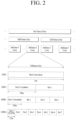
- FIG. 2 illustrates a structure of a radio frame used in NR.
- Each radio frame has a length of 10 ms and is divided into two 5-ms half frames (HFs). Each half frame is divided into five 1-ms subframes. A subframe is divided into one or more slots, and the number of slots in a subframe depends on an SCS.
- Each slot includes 12 or 14 OFDM(A) symbols according to a CP. When a normal CP is used, each slot includes 14 OFDM symbols. When an extended CP is used, each slot includes 12 OFDM symbols.
- a symbol may include an OFDM symbol (CP-OFDM symbol) and an SC-FDMA symbol (or DFT-s-OFDM symbol) .
- multiple numerologies may be available to UEs in the NR system.
- a subcarrier spacing (SCS) is 15 kHz
- a wide area of the typical cellular bands is supported.
- SCS is 30 kHz/60 kHz
- a dense-urban, lower latency, wider carrier bandwidth is supported.
- the SCS is 60 kHz or higher
- a bandwidth that is greater than 24.25 GHz is supported in order to overcome phase noise.
- the numerologies may be defined by a cyclic prefix (CP) length and a SCS.
- a single cell can provide a plurality of numerologies to UEs.
- CP cyclic prefix
- OFDM(A) numerologies e.g., SCS, CP length, and so on
- a (absolute time) duration (or section) of a time resource e.g., subframe, slot or TTI
- a time unit (TU) for simplicity
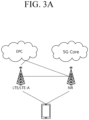
- FIGS. 3A to 3C illustrate exemplary architectures for a wireless communication service.
- a UE is connected in dual connectivity (DC) with an LTE/LTE-A cell and a NR cell.
- DC dual connectivity
- a pair of spectrums indicates including two subcarriers for downlink and uplink operations.
- one subcarrier in one pair of spectrums may include a pair of a downlink band and an uplink band.
- the downlink or uplink transmission is performed through an activated BWP, and only one BWP among the BWPs configured for the UE may be activated at a given time.
- each element is referred to as a resource element (RE), and one complex symbol may be mapped to it.
- RE resource element
- Such a subframe (or slot) structure may be called a self-contained subframe (or slot).
- this subframe (or slot) structure When this subframe (or slot) structure is used, a time taken to retransmit data that has failed in reception may be reduced to minimize final data transmission latency.
- a time gap may be required in a process of transition from a transmission mode to a reception mode or from the reception mode to the transmission mode.
- some OFDM symbols when DL switches to UL in the subframe structure can be configured to a guard period (GP).
- the frame has a self-contained structure, in which all of a DL control channel, DL or UL data channel, UL control channel, and other elements are included in one slot.
- the first N symbols (hereinafter referred to as a DL control region) in a slot may be used for transmitting a DL control channel
- the last M symbols (hereinafter referred to as a UL control region) in the slot may be used for transmitting an UL control channel.
- N and M are integers greater than 0.
- a resource region between the DL control region and the UL control region (hereinafter referred to as a data region) may be used for DL data transmission or UL data transmission.
- the following configurations may be taken into account. The durations are listed in temporal order.
- a GP provides a time gap during a process where a gNB and a UE transition from the transmission mode to the reception mode or a process where the gNB and UE transition from the reception mode to the transmission mode.
- Part of symbols belonging to the occasion in which the mode is changed from DL to UL within a subframe may be configured as the GP.
- a carrier aggregation system will be described.
- the carrier aggregation system may support the cross-carrier scheduling.
- the cross-carrier scheduling refers to a scheduling method capable of performing resource allocation of a PDSCH transmitted by a different component carrier through a PDCCH transmitted through a specific CC and/or resource allocation of a PUSCH transmitted by another CC other than a CC primarily linked to the specific CC. That is, the PDCCH and the PDSCH may be transmitted through different DL CCs, and the PUSCH may be transmitted through a UL CC other than a UL CC linked to a DL CC on which a PDCCH including a UL grant is transmitted.
- the base station may configure a PDCCH monitoring DL CC (monitoring CC) set.
- the PDCCH monitoring DL CC set consists of some DL CCs among all aggregated DL CCs.
- a UE performs PDCCH monitoring/decoding only for the DL CC included in the PDCCH monitoring DL CC set.
- the base station uses only the DL CCs included in the PDCCH monitoring DL CC set to transmit the PDCCH for the PDSCH/PUSCH to be scheduled.
- the PDCCH monitoring DL CC set may be configured in a UE-specific, UE group-specific, or cell-specific manner.
- FIG. 7 shows an example where three DL CCs (e.g., DL CC A, DL CC B, and DL CC C) are aggregated, and the DL CC A is configured as the PDCCH monitoring DL CC.
- the UE may receive scheduling information (i.e., the DCI including a DL grant) for the PDSCH of the DL CC A, DL CC B, and DL CC C through the PDCCH of the DL CC A.
- the DCI transmitted through the PDCCH of the DL CC A may include the CIF to indicate which DL CC the DCI is for.
- each of the scheduling control information for PDSCH #1 and PDSCH #2 transmitted on each of that cell #A and that cell #B is separately configured for each of DCI #1 and DCI #2 and transmitted through each of PDCCH #1 and PDCCH #2.
- DSS dynamic spectrum sharing
- the DSS may be implemented by using some resources of certain LTE DL subframes in the LTE frequency band for the NR PDCCH, PDSCH and DM RS transmission, using some resources of the LTE UL subframes for the NR PUSCH, PUCCH and DM RS transmission, among others.
- the LTE frequency band is often configured in a low frequency band compared to that of NR and therefore one base station is capable of supporting wider cell coverage in terms of cell coverage.
- NR cells configured in a high frequency band may be suitable for small cells for data boosting.
- the NR cells configured based on the DSS in the LTE band for any terminal may be configured as the primary cell (PCell), and the NR cells configured in the NR frequency band may be configured as the secondary cell (SCell).
- PCell primary cell
- SCell secondary cell
- any DSS-based carrier or cell supporting both LTE/NR transmits both the LTE PDCCH and the NR PDCCH, or when the CA for a plurality of cells is configured or activated for any terminal to transmit bulk data, there is a need to consider how to enhance the spectral efficiency in the PDCCH transmission.
- the scheduling control information for each PDSCH or PUSCH transmission is individually transmitted, there may be problems of insufficient PDCCH capacity, low spectral efficiency due to frequency waste from redundant transmission of some pieces of the same information (e.g., CRC, etc.).
- the present specification introduces a method and device for allocating PDSCH or PUSCH for one or more cells using a single DCI when a terminal is configured for CA.
- a single DCI transmitted to a terminal may include scheduling information for a group that includes the cells.
- cross-carrier scheduling may group a scheduling cell that performs scheduling and a scheduled cell that is scheduled as one group. For example, when the number of cells that can be scheduled through a single DCI is two, one cell may be the scheduling cell capable of scheduling for the DCI transmission and the other cell may be the scheduled cell scheduled for the data channel by the scheduling cell.
- the cross-carrier scheduling may be configured for any SCell through an RRC message.
- Table 5 shows an example of an RRC message format for configuring the cross-carrier scheduling.
- the configuration values for the PCell and the PSCell in ⁇ schedulingCellInfo' were limited to ⁇ own', and it was thus possible to operate the PCell and PSCell as the cells (i.e., the scheduling cells) capable of scheduling other cells.
- cross-carrier scheduling configuration information of each cell may be configured to indicate whether to transmit the scheduling control information for a corresponding cell through the corresponding cell (i.e., a self-scheduling method in which the scheduling cell is configured as 'own') or whether to transmit the scheduling control information for the corresponding cell through another cell (e.g.,, a cross-carrier scheduling method in which the scheduling cell is configured as 'other').
- the cif-Presence may be configured to indicate whether to transmit the scheduling control information for other cells through that cell, i.e., whether to operate as a scheduling cell based on the cross-carrier scheduling configuration.
- This disclosure introduces a method of supporting multi-cell scheduling through 1:1 grouping of a scheduling cell and a scheduled cell.
- multi(-cell) carrier indicator field (mcif)-Presence may be additionally configured to define whether to support the multi-cell scheduling.
- the scheduling DCI i.e., the DL assignment DCI or UL grant DCI
- the scheduling DCI transmitted through the scheduling cell includes an mcif information area.
- the mcif refers to information (or an information area) indicating whether the scheduling DCI includes multi-cell scheduling information.
- 'mcif' is merely an exemplary term, and may be replaced by a group carrier indicator field (gcif).
- the corresponding DCI may be defined to include resource allocation information for the scheduling cell in addition to resource allocation information for the scheduled cell configured by the cif.
- the cell A may be configured as a scheduling cell
- the cell B and the cell C may be configured as scheduled cells to be scheduled by the cell A (i.e., the scheduled cells).
- the base station may configure the mcif-presence based on the cross-carrier scheduling configuration information for the cell A.
- the mcif-presence may be defined to include mcif in the scheduling DCI transmitted through the cell A and perform the multi-cell scheduling based on a combination of the mcif and the cif.
- cif indicates whether that scheduling DCI is the scheduling information for the cell A, the scheduling information for the cell B, or the scheduling information for the cell C.
- the mcif may be defined to additionally indicate whether that scheduling information is single cell scheduling information for the cell B or cell C or whether that scheduling information is multi-cell scheduling information for the cell A + the cell B or the cell A + the cell C in addition to the scheduling information for the scheduling cell (i.e., the cell A).
- mcif may indicate whether the scheduling information is the single cell scheduling information for the cell B or cell C or the multi-cell scheduling information for both the cell A and the cell B or both the cell A and the cell C.
- the scheduled cell may be configured to be always scheduled to include the scheduling cell.
- the multi-cell scheduling in this example may be configured through the cross-carrier scheduling configuration for the scheduled cell.
- the scheduling DCI for the scheduled cell may be defined to always include the scheduling control information for the scheduling cell. For example, when the cell A, the cell B, and the cell C are set for a terminal, the cell A may be configured as a scheduling cell, and the cell B and the cell C may be configured as scheduled cells.
- the base station may include the multi-cell scheduling configuration information in addition to schedulingCellID information and cif-inschedulingCell information through the cross-carrier scheduling configuration information for the cell B or the cell C. Therefore, according to whether the multi-cell scheduling is configured, it is determined whether the scheduled cell is scheduled through the single cell scheduling as before or scheduled through the multi-cell scheduling together with the scheduling cell. In other words, when the multi-cell scheduling is not configured, and the CIF of the scheduling DCI transmitted through the cell A indicates the cell B or the cell C as before, each DCI includes only the single cell scheduling information for the cell B or the cell C.
- the scheduled cell when the multi-cell scheduling is configured for a scheduled cell, the scheduled cell may be scheduled together with the scheduling cell, i.e., the cell A.
- the scheduling control information for the cell B may include the scheduling control information for the scheduling cell (e.g., the cell A).
- the scheduling DCI when the cif of the scheduling DCI transmitted through the cell A indicates the cell B, the scheduling DCI may be defined to include the scheduling information for the cell A together with the scheduling information for the cell B.
- the embodiment described above is a method of supporting the multi-cell scheduling only for two cells: the scheduling cell and the scheduled cell.
- the base station may configure the multi-cell scheduling for a terminal through the RRC signaling.
- one scheduling DCI may include configuration information about the number of cells to be scheduled through the one scheduling DCI.
- the RRC signaling or message for the multi-cell scheduling configuration may include cgif-inschedulingcell information.
- the cell group indication field (cgif) refers to cell group information indicated by the scheduling DCI, in which one cell group includes cells corresponding to a previously configured number of cells.
- the base station may configure the cell A as the scheduling cell through the RRC message for the multi-cell scheduling configuration.
- the multi-cell scheduling information for the cell B, the cell C, and the cell D includes cgif configuration information together with the scheduling cell ID for performing the scheduling for each cell.
- one or more pieces of cgif information may be configured for one cell.
- one cell may belong to one or more cell groups. Therefore, the scheduling DCI transmitted from the scheduling cell (e.g., the cell A) includes the cgif, and the cell group to be scheduled is indicated through that DCI transmitted including the cgif. In this case, all the cell groups may be defined to include the scheduling cell.
- the maximum number of cells to be scheduled through single DCI may be configured through the multi-cell scheduling configuration information.
- the maximum number of cells (e.g., Nmax) may be configured equally to the maximum number of cells to be scheduled through single DCI, and one cell group may include the cell(s), the number of which is smaller than or equal to Nmax.
- the maximum number of cells (e.g., Nmax) may be configured through the RRC message for the multi-cell scheduling.
- the RRC signaling for the multi-cell scheduling configuration may be applied in the same way except that the maximum number of cells (e.g., Nmax) is configured instead of the number of cells (e.g., N) .
- a set of cells which includes up to 4 cells, may be configured for a terminal.
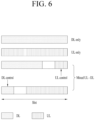
- one set of cells which includes the cell A, the cell B, the cell C, and the cell D, may be configured for a terminal, and may be defined to indicate group information about cells to be scheduled together (i.e., co-scheduled cells) among the cell A, the cell B, the cell C, and the cell D through one multi-cell scheduling DCI format (i.e., information about a combination of co-scheduled cells.
- Grouping information about co-scheduled cells may be configured through the RRC signaling as described above.
- any co-scheduled cell group may be tabulated as shown in the following Table 5.
- the base station may indicate a table index through the cgif indicated based on the multi-cell scheduling DCI format, and thus indicate a cell group in which a co-scheduled cell combination is scheduled through that DCI.
- [Table 6] index Co-scheduled cell combination 0 Cell A, cell B, cell C, cell D 1 Cell A, cell B, cell C 2 Cell A, cell B, cell D 3 Cell A, cell C, cell D 4 Cell B, cell C, cell D 5 Cell A, cell B 6 Cell A, cell C 7 Cell A, cell D 8 Cell B, cell C 9 Cell B, cell D 10 Cell C, Cell D
- the payload size of the multi-cell scheduling DCI format may be determined based on the maximum number of cells to be co-scheduled through the corresponding DCI to be described later in the method of the following second disclosure (i.e., the maximum number of cells that constitute the co-scheduled cell combination of FIG. 6 ). Specifically, the payload size of the multi-cell scheduling DCI format may be determined based on the maximum number of cells and the maximum payload size determined by the active DL or UL BWP of the corresponding cells.
- the multi-cell scheduling configuration may be transmitted in the form of a cross-carrier scheduling configuration RRC message, or the RRC message may be defined for separate multi-cell scheduling.
- Second disclosure Method of dynamically scheduling multiple cells based on a bitmap
- a single scheduling DCI for multi-cell scheduling may be defined to include cell indication information for indicating cells to be scheduled through the single scheduling DCI, and the cell indication information may be bitmap information.
- a scheduling cell may be configured for the multi-cell scheduling by the base station.
- the base station may transmit the multi-cell scheduling DCI, which includes the scheduling control information about one or more cells, through the scheduling cell.
- the multi-cell scheduling DCI includes the bitmap information for indicating one or more cells to be scheduled through that DCI.
- a bitmap size for indicating one or more cells may be included in the RRC message for the multi-cell scheduling configuration.
- bitmap size configuration information may be transmitted directly, or the configuration information about the maximum number of cells to be scheduled through a single DCI (e.g., Nmax) may be transmitted, so that the corresponding bitmap size and the corresponding payload size of the multi-cell scheduling DCI can be determined.
- Nmax the configuration information about the maximum number of cells to be scheduled through a single DCI
- bitmap size configuration information may be directly transmitted to the terminal through the RRC message, or ii) the configuration information about the maximum number of cells (e.g., Nmax) to be scheduled through single DCI may be transmitted to the terminal through the RRC message, so that the bitmap size can be determined based on the maximum number of cells (e.g., Nmax).
- the payload size of the multi-cell scheduling DCI may also be determined based on the bitmap size.
- the cell to be scheduled through the multi-cell scheduling DCI (i.e., the scheduled cell) is also configured through the RRC message for the multi-cell scheduling.
- the configuration information for the scheduled cell may include i) scheduling cell ID information transmitted through multi-cell scheduling DCI, ii) information on a position of a bit indicating the scheduled cell within the bitmap, and iii) information on a location for transmitting the corresponding resource allocation information regions.
- the configuration information for the scheduled cell may include i) the scheduling cell ID information, ii) the location information on the bit indicating the scheduled cell, and iii) the information about the location of transmitting which the resource allocation information regions.
- the multi-cell scheduling RRC message may be defined as a separate RRC message as a variation of the previously mentioned cross-carrier scheduling RRC message.
- the multi-cell scheduling may be restricted to scheduled cells configured for the cross-carrier scheduling and scheduled by the scheduling cell.
- the multi-cell scheduling DCI for #A, #B, and #C may be defined to be transmitted only from a single scheduling cell based on the cross-carrier scheduling configuration. This may correspond to a case where a scheduling cell transmits the multi-cell scheduling DCI for the plurality of scheduled cells by using the aforementioned method.
- this may include a case where the plurality of scheduling cells transmit the multi-cell scheduling DCI for the plurality of scheduled cells.
- one or more cells may serve as both the scheduling cell of the multi-cell scheduling and the scheduled cells.
- each of the cells #A, #B, and #C may transmit the multi-cell scheduling DCI for the three cells without separate cross-carrier scheduling.
- multi-cell scheduling control information may be transmitted and received by using the aforementioned method except for the parts related to the cross-carrier scheduling configuration.
- the "method of dynamically scheduling multiple cells based on the cell group indicator" described in the first disclosure and the "method of dynamically scheduling multiple cells based on the bitmap" described in the second disclosure may be implemented in combination.
- the bitmap information included in the DCI transmitted from the base station to the terminal may indicate cell group identification information.
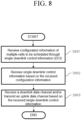
- FIG. 8 illustrates an operation method of a terminal according to an embodiment of the present specification.
- a terminal receives configuration information of multiple cells to be scheduled through single downlink control information (DCI) from a base station (S801).
- DCI downlink control information
- RRC radio resource control
- the terminal receives the single DCI for the multiple cells, based on the configuration information of multiple cells received from the base station (S802).
- the received single DCI may include information for identifying the multiple cells.
- the information for identifying the multiple cells may be cell group indication information that indicates the multiple cells, which may also be bitmap-based information.
- the terminal receives a downlink data channel and/or transmits an uplink data channel based on the received single DCI (S803).
- the downlink data channel may be a PDSCH
- the uplink data channel may be a PUSCH.
- the terminal receives the configuration information of multiple cells scheduled through the single DCI from the base station.
- the number of cells may be smaller than or equal to the maximum number of cells to be scheduled through the single DCI.
- FIG. 9 illustrates an operation method of a base station according to an embodiment of the present specification.
- a base station transmits configuration information of multiple cells to be scheduled through single downlink control information (DCI) to a terminal (S901).
- DCI downlink control information
- the configuration information of multiple cells may be transmitted to the terminal through a radio resource control (RRC) message.
- RRC radio resource control
- the base station After transmitting the configuration information of multiple cells to the terminal, the base station transmits the single DCI for the multiple cells (S902).
- the transmitted single DCI may include information identifying the multiple cells.
- the information identifying the multiple cells may be cell group indication information that indicates the multiple cells. Further, the information may be bitmap-based information.
- the base station After transmitting the single DCI for the multiple cells, the base station transmits a downlink data channel and/or receives an uplink data channel (S903).
- the downlink data channel may be a PDSCH, and the uplink data channel may be a PUSCH.
- the base station transmits the configuration information of the multiple cells scheduled through the single DCI to the terminal.
- the number of cells may be smaller than or equal to the maximum number of cells to be scheduled through the single DCI.
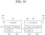
- FIG. 10 shows apparatuses according to an embodiment of the disclosure.
- a wireless communication system may include a first apparatus 100a and a second apparatus 100b.
- the first apparatus 100a may include a base station, a network node, a transmission UE, a reception UE, a wireless apparatus, a radio communication device, a vehicle, a vehicle with an autonomous driving function, a connected car, an unmanned aerial vehicle (UAV), an artificial intelligence (AI) module, a robot, an augmented reality (AR) apparatus, a virtual reality (VR) apparatus, a mixed reality (MR) apparatus, a hologram apparatus, a public safety apparatus, a machine-type communication (MTC) apparatus, an Internet of things (IoT) apparatus, a medial apparatus, a finance technology (FinTech) apparatus (or a financial apparatus), a security apparatus, a climate/environment apparatus, an apparatus related to a 5G service, or other apparatuses related to the fourth industrial revolution.
- UAV unmanned aerial vehicle
- AI artificial intelligence
- AR augmented reality
- VR virtual reality
- MR mixed reality
- hologram apparatus a public safety apparatus
- MTC machine-type communication
- the second apparatus 100b may include a base station, a network node, a transmission UE, a reception UE, a wireless apparatus, a radio communication device, a vehicle, a vehicle with an autonomous driving function, a connected car, an unmanned aerial vehicle (UAV), an artificial intelligence (AI) module, a robot, an augmented reality (AR) apparatus, a virtual reality (VR) apparatus, a mixed reality (MR) apparatus, a hologram apparatus, a public safety apparatus, a machine-type communication (MTC) apparatus, an Internet of things (IoT) apparatus, a medial apparatus, a finance technology (FinTech) apparatus (or a financial apparatus), a security apparatus, a climate/environment apparatus, an apparatus related to a 5G service, or other apparatuses related to the fourth industrial revolution.
- UAV unmanned aerial vehicle
- AI artificial intelligence
- AR augmented reality
- VR virtual reality
- MR mixed reality
- hologram apparatus a public safety apparatus
- MTC machine-type communication
- the second apparatus 100b may include at least one processor such as a processor 1020b, at least one memory device such as a memory 1010b, and at least one transceiver such as a transceiver 1031b.
- the processor 1020b may perform the foregoing functions, procedures, and/or methods.
- the processor 1020b may implement one or more protocols.
- the processor 1020b may implement one or more layers of a radio interface protocol.
- the memory 1010b may be connected to the processor 1020b and configured to store various types of information and/or instructions.
- the transceiver 1031b may be connected to the processor 1020b and controlled to transceive radio signaling.
- the first apparatus 100a and/or the second apparatus 100b may have one or more antennas.
- an antenna 1036a and/or an antenna 1036b may be configured to transceive a radio signal.
- FIG. 11 is a block diagram showing a configuration of a terminal according to an embodiment of the disclosure.
- FIG. 11 illustrates the foregoing apparatus of FIG. 10 in more detail.
- the apparatus includes a memory 1010, a processor 1020, a transceiving unit 1031, a power management module 1091, a battery 1092, a display 1041, an input unit 1053, a loudspeaker 1042, a microphone 1052, a subscriber identification module (SIM) card, and one or more antennas.
- a memory 1010 a processor 1020, a transceiving unit 1031, a power management module 1091, a battery 1092, a display 1041, an input unit 1053, a loudspeaker 1042, a microphone 1052, a subscriber identification module (SIM) card, and one or more antennas.
- SIM subscriber identification module
- the processor 1020 may be configured to implement the proposed functions, procedures, and/or methods described in the disclosure.
- the layers of the radio interface protocol may be implemented in the processor 1020.
- the processor 1020 may include an application-specific integrated circuit (ASIC), other chipsets, logic circuits, and/or data processing devices.
- the processor 1020 may be an application processor (AP).
- the processor 1020 may include at least one of a digital signal processor (DSP), a central processing unit (CPU), a graphics processing unit (GPU), and a modulator and demodulator (MODEM).
- DSP digital signal processor
- CPU central processing unit
- GPU graphics processing unit
- MODEM modulator and demodulator
- the processor 1020 may be SNAPDRAGON TM series of processors made by Qualcomm ® , EXYNOS TM series of processors made by Samsung ® , A series of processors made by Apple ® , HELIO TM series of processors made by MediaTek ® , ATOM TM series of processors made by Intel ® , KIRIN TM series of processors made by HiSilicon ® , or the corresponding next-generation processors.
- the power management module 1091 manages a power for the processor 1020 and/or the transceiver 1031.
- the battery 1092 supplies power to the power management module 1091.
- the display 1041 outputs the result processed by the processor 1020.
- the input unit 1053 receives an input to be used by the processor 1020.
- the input unit 1053 may be displayed on the display 1041.
- the SIM card is an integrated circuit used to safely store international mobile subscriber identity (IMSI) used for identifying a subscriber in a mobile telephoning apparatus such as a mobile phone and a computer and the related key. Many types of contact address information may be stored in the SIM card.
- IMSI international mobile subscriber identity
- the memory 1010 is coupled with the processor 1020 in a way to operate and stores various types of information to operate the processor 1020.
- the memory may include read-only memory (ROM), random access memory (RAM), flash memory, a memory card, a storage medium, and/or other storage device.
- ROM read-only memory
- RAM random access memory
- flash memory a memory card
- storage medium e.g., hard disk drives
- a module may be stored in the memory 1010 and executed by the processor 1020.
- the memory may be implemented inside of the processor 1020.
- the memory 1010 may be implemented outside of the processor 1020 and may be connected to the processor 1020 in communicative connection through various means which is well-known in the art.
- the transceiver 1031 is connected to the processor 1020 in a way to operate and transmits and/or receives a radio signal.
- the transceiver 1031 includes a transmitter and a receiver.
- the transceiver 1031 may include a baseband circuit to process a radio frequency signal.
- the transceiver controls one or more antennas to transmit and/or receive a radio signal.
- the processor 1020 transfers command information to the transceiver 1031 to transmit a radio signal that configures a voice communication data.
- the antenna functions to transmit and receive a radio signal.
- the transceiver 1031 may transfer a signal to be processed by the processor 1020 and transform a signal in baseband. The processed signal may be transformed into audible or readable information output through the speaker 1042.
- the speaker 1042 outputs a sound related result processed by the processor 1020.
- the microphone 1052 receives a sound related input to be used by the processor 1020.
- a user inputs command information like a phone number by pushing (or touching) a button of the input unit 1053 or a voice activation using the microphone 1052.
- the processor 1020 processes to perform a proper function such as receiving the command information, calling a call number, and the like.
- An operational data on driving may be extracted from the SIM card or the memory 1010.
- the processor 1020 may display the command information or driving information on the display 1041 for a user's recognition or for convenience.
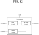
- FIG. 12 is a configuration block diagram of a processor in which the disclosure is implemented.
- a processor 1020 in which the disclosure of the present specification is implemented may include a plurality of circuitry to implement the proposed functions, procedures and/or methods described herein.
- the processor 1020 may include a first circuit 1020-1, a second circuit 1020-2, and a third circuit 1020-3.
- the processor 1020 may include more circuits. Each circuit may include a plurality of transistors.
- the processor 1020 may be referred to as an application-specific integrated circuit (ASIC) or an application processor (AP), and may include at least one of a digital signal processor (DSP), a central processing unit (CPU), and a graphics processing unit (GPU).
- ASIC application-specific integrated circuit
- AP application processor
- DSP digital signal processor
- CPU central processing unit
- GPU graphics processing unit
- FIG. 13 is a detailed block diagram of a transceiver of a first apparatus shown in FIG. 10 or a transceiving unit of an apparatus shown in FIG. 11 .
- the transceiving unit 1031 includes a transmitter 1031-1 and a receiver 1031-2.
- the transmitter 1031-1 includes a discrete Fourier transform (DFT) unit 1031-11, a subcarrier mapper 1031-12, an IFFT unit 1031-13, a cyclic prefix (CP) insertion unit 1031-14, and a wireless transmitting unit 1031-15.
- the transmitter 1031-1 may further include a modulator.
- the transmitter 1031-1 may for example include a scramble unit (not shown), a modulation mapper (not shown), a layer mapper (not shown), and a layer permutator (not shown), which may be disposed before the DFT unit 1031-11.
- the transmitter 1031-1 subjects information to the DFT unit 1031-11 before mapping a signal to a subcarrier.
- the signal spread (or pre-coded) by the DFT unit 1031-11 is mapped onto a subcarrier by the subcarrier mapper 1031-12 and made into a signal on the time axis through the IFFT unit 1031-13.
- the DFT unit 1031-11 performs DFT on input symbols to output complex-valued symbols. For example, when Ntx symbols are input (here, Ntx is a natural number), DFT has a size of Ntx.
- the DFT unit 1031-11 may be referred to as a transform precoder.
- the subcarrier mapper 1031-12 maps the complex-valued symbols onto respective subcarriers in the frequency domain. The complex-valued symbols may be mapped onto resource elements corresponding to resource blocks allocated for data transmission.
- the subcarrier mapper 1031-12 may be referred to as a resource element mapper.
- the IFFT unit 1031-13 performs IFFT on the input symbols to output a baseband signal for data as a signal in the time domain.
- the CP inserting unit 1031-14 copies latter part of the baseband signal for data and inserts the latter part in front of the baseband signal for data.
- CP insertion prevents inter-symbol interference (ISI) and inter-carrier interference (ICI), thereby maintaining orthogonality even in a multipath channel.
- ISI inter-symbol interference
- ICI inter-carrier interference
- the receiver 1031-2 includes a wireless receiving unit 1031-21, a CP removing unit 1031-22, an FFT unit 1031-23, and an equalizing unit 1031-24.
- the wireless receiving unit 1031-21, the CP removing unit 1031-22, and the FFT unit 1031-23 of the receiver 1031-2 perform reverse functions of the wireless transmitting unit 1031-15, the CP inserting unit 1031-14, and the IFFT unit 1031-13 of the transmitter 1031-1.
- the receiver 1031-2 may further include a demodulator.
- Claims of the present disclosure may be combined in various manners. For example, technical features of the method claim of the present disclosure may be combined to implement a device, and technical features of the device claim of the present disclosure may be combined to implement a method. In addition, the technical features of the method claim and the technical features of the device claim of the present disclosure may be combined to implement a device, and technical features of the method claim and the technical features of the device claim of the present disclosure may be combined to implement a method.
Landscapes
- Engineering & Computer Science (AREA)
- Signal Processing (AREA)
- Computer Networks & Wireless Communication (AREA)
- Mobile Radio Communication Systems (AREA)
Applications Claiming Priority (3)
| Application Number | Priority Date | Filing Date | Title |
|---|---|---|---|
| KR20220036325 | 2022-03-23 | ||
| KR1020230035794A KR20230140492A (ko) | 2022-03-23 | 2023-03-20 | 무선 통신 시스템에서 데이터 채널을 스케줄링 하는 방법 및 장치 |
| PCT/KR2023/003798 WO2023182806A1 (fr) | 2022-03-23 | 2023-03-22 | Procédé et dispositif de planification d'un canal de données dans un système de communication sans fil |
Publications (2)
| Publication Number | Publication Date |
|---|---|
| EP4486036A1 true EP4486036A1 (fr) | 2025-01-01 |
| EP4486036A4 EP4486036A4 (fr) | 2026-02-25 |
Family
ID=88101833
Family Applications (1)
| Application Number | Title | Priority Date | Filing Date |
|---|---|---|---|
| EP23775302.5A Pending EP4486036A4 (fr) | 2022-03-23 | 2023-03-22 | Procédé et dispositif de planification d'un canal de données dans un système de communication sans fil |
Country Status (3)
| Country | Link |
|---|---|
| US (1) | US20250016794A1 (fr) |
| EP (1) | EP4486036A4 (fr) |
| WO (1) | WO2023182806A1 (fr) |
Families Citing this family (2)
| Publication number | Priority date | Publication date | Assignee | Title |
|---|---|---|---|---|
| US12550161B2 (en) * | 2022-04-29 | 2026-02-10 | Apple Inc. | Methods for DCI configurations and procedures with multi-cell scheduling DCI |
| US12414126B2 (en) * | 2022-08-08 | 2025-09-09 | Qualcomm Incorporated | Scheduled cell identification for multi-cell scheduling |
Family Cites Families (5)
| Publication number | Priority date | Publication date | Assignee | Title |
|---|---|---|---|---|
| WO2021134771A1 (fr) * | 2020-01-03 | 2021-07-08 | Qualcomm Incorporated | Utilisation d'un décalage temporel dans des informations de commande de liaison descendante qui programme de multiples cellules |
| WO2021142760A1 (fr) * | 2020-01-17 | 2021-07-22 | Qualcomm Incorporated | Élément unique de dci mettant à jour des paramètres de commande pour de multiples porteuses composantes |
| KR102927643B1 (ko) * | 2020-03-31 | 2026-02-20 | 삼성전자주식회사 | 무선 통신 시스템에서 통신을 수행하는 방법 및 장치 |
| US20220046688A1 (en) * | 2020-08-06 | 2022-02-10 | Lg Electronics Inc. | Method and apparatus for transmitting/receiving wireless signal in wireless communication system |
| WO2022047348A2 (fr) * | 2020-08-31 | 2022-03-03 | Yunjung Yi | Validation d'informations de commande de liaison descendante multi-cellule |
-
2023
- 2023-03-22 WO PCT/KR2023/003798 patent/WO2023182806A1/fr not_active Ceased
- 2023-03-22 EP EP23775302.5A patent/EP4486036A4/fr active Pending
-
2024
- 2024-09-19 US US18/890,285 patent/US20250016794A1/en active Pending
Also Published As
| Publication number | Publication date |
|---|---|
| WO2023182806A1 (fr) | 2023-09-28 |
| US20250016794A1 (en) | 2025-01-09 |
| EP4486036A4 (fr) | 2026-02-25 |
Similar Documents
| Publication | Publication Date | Title |
|---|---|---|
| EP4539579A1 (fr) | Procédé et dispositif de configuration de format de créneau pour une communication en duplex intégral dans un système de communication sans fil | |
| EP4503806A1 (fr) | Procédé et dispositif de configuration de structure de trame pour une communication en duplex intégral | |
| US20250016794A1 (en) | Method and device for scheduling data channel in wireless communication system | |
| KR20240009867A (ko) | 무선 통신 시스템에서 전이중통신(Full Duplex)을 위한 슬롯 포맷 설정 방법 및 장치 | |
| US20250184105A1 (en) | Method and apparatus of configuring subband for full duplex in wireless communication system | |
| EP4646004A1 (fr) | Procédé et appareil de détermination d'occasion de rach dans une communication en duplex intégral de sous-bande | |
| US20250344254A1 (en) | Method and apparatus for determining a rach resource type in subband full-duplex communication | |
| KR20240018359A (ko) | 무선 통신 시스템에서 전이중통신(Full Duplex)을 위한 서브밴드 설정 방법 및 장치 | |
| EP4642111A1 (fr) | Procédé et appareil de détermination de puissance de transmission rach dans une communication en duplex intégral de sous-bande | |
| US20250015950A1 (en) | Method and device for transmitting and receiving new radio technology (nr) physical downlink control channel (pdcch) in wireless communication system | |
| EP4451780A1 (fr) | Procédé et appareil de commande de transmission en liaison montante dans un système de communication sans fil | |
| US20250350420A1 (en) | Method and apparatus for full duplex in wireless communication system | |
| US20260032657A1 (en) | Method and apparatus for scheduling at least one uplink data channel for full duplex communication | |
| EP4648343A1 (fr) | Procédé et appareil pour effectuer un accès aléatoire dans une communication en duplex intégral de sous-bande | |
| EP4336911A1 (fr) | Procédé et appareil de signalisation pour économie d'énergie de réseau | |
| EP4604655A1 (fr) | Procédé et appareil pour effectuer une procédure d'accès aléatoire dans un duplex intégral de sous-bande | |
| EP4456645A1 (fr) | Procédé et appareil de commande de transmission en liaison montante dans un système de communication sans fil | |
| EP4459914A1 (fr) | Procédé et appareil de transmission en liaison montante dans un système de communication sans fil | |
| EP4604630A1 (fr) | Procédé et appareil pour augmenter la puissance de transmission de préambule dans un duplex intégral de sous-bande | |
| EP4270814A1 (fr) | Procédé et appareil d'émission-réception d'informations de commande de faisceau de répéteur dans un système de communication mobile | |
| EP4633249A1 (fr) | Procédé et appareil d'émission-réception de signal de faible puissance | |
| KR20230140492A (ko) | 무선 통신 시스템에서 데이터 채널을 스케줄링 하는 방법 및 장치 | |
| KR20240149805A (ko) | 전이중통신을 위한 적어도 하나의 상향링크 데이터 채널 스케줄링 방법 및 장치 | |
| KR20230153932A (ko) | 전이중통신을 위한 프레임 구조 설정 방법 및 장치 | |
| KR20240122335A (ko) | 전이중통신을 지원하는 무선 통신 시스템에서 무선 자원을 설정하는 방법 및 장치 |
Legal Events
| Date | Code | Title | Description |
|---|---|---|---|
| STAA | Information on the status of an ep patent application or granted ep patent |
Free format text: STATUS: THE INTERNATIONAL PUBLICATION HAS BEEN MADE |
|
| PUAI | Public reference made under article 153(3) epc to a published international application that has entered the european phase |
Free format text: ORIGINAL CODE: 0009012 |
|
| STAA | Information on the status of an ep patent application or granted ep patent |
Free format text: STATUS: REQUEST FOR EXAMINATION WAS MADE |
|
| 17P | Request for examination filed |
Effective date: 20240923 |
|
| AK | Designated contracting states |
Kind code of ref document: A1 Designated state(s): AL AT BE BG CH CY CZ DE DK EE ES FI FR GB GR HR HU IE IS IT LI LT LU LV MC ME MK MT NL NO PL PT RO RS SE SI SK SM TR |
|
| DAV | Request for validation of the european patent (deleted) | ||
| DAX | Request for extension of the european patent (deleted) | ||
| A4 | Supplementary search report drawn up and despatched |
Effective date: 20260123 |
|
| RIC1 | Information provided on ipc code assigned before grant |
Ipc: H04W 72/12 20230101AFI20260119BHEP Ipc: H04W 72/23 20230101ALI20260119BHEP Ipc: H04L 5/00 20060101ALI20260119BHEP |