EP4488043A1 - Dispositif de montage d'une carcasse de pneu pour un pneu de véhicule - Google Patents
Dispositif de montage d'une carcasse de pneu pour un pneu de véhicule Download PDFInfo
- Publication number
- EP4488043A1 EP4488043A1 EP24184860.5A EP24184860A EP4488043A1 EP 4488043 A1 EP4488043 A1 EP 4488043A1 EP 24184860 A EP24184860 A EP 24184860A EP 4488043 A1 EP4488043 A1 EP 4488043A1
- Authority
- EP
- European Patent Office
- Prior art keywords
- carriage
- central shaft
- along
- destructively
- sliding sleeve
- Prior art date
- Legal status (The legal status is an assumption and is not a legal conclusion. Google has not performed a legal analysis and makes no representation as to the accuracy of the status listed.)
- Pending
Links
Images
Classifications
-
- B—PERFORMING OPERATIONS; TRANSPORTING
- B29—WORKING OF PLASTICS; WORKING OF SUBSTANCES IN A PLASTIC STATE IN GENERAL
- B29D—PRODUCING PARTICULAR ARTICLES FROM PLASTICS OR FROM SUBSTANCES IN A PLASTIC STATE
- B29D30/00—Producing pneumatic or solid tyres or parts thereof
- B29D30/06—Pneumatic tyres or parts thereof (e.g. produced by casting, moulding, compression moulding, injection moulding, centrifugal casting)
- B29D30/08—Building tyres
- B29D30/20—Building tyres by the flat-tyre method, i.e. building on cylindrical drums
- B29D30/24—Drums
- B29D30/244—Drums for manufacturing substantially cylindrical tyre components with cores or beads, e.g. carcasses
-
- B—PERFORMING OPERATIONS; TRANSPORTING
- B29—WORKING OF PLASTICS; WORKING OF SUBSTANCES IN A PLASTIC STATE IN GENERAL
- B29D—PRODUCING PARTICULAR ARTICLES FROM PLASTICS OR FROM SUBSTANCES IN A PLASTIC STATE
- B29D30/00—Producing pneumatic or solid tyres or parts thereof
- B29D30/06—Pneumatic tyres or parts thereof (e.g. produced by casting, moulding, compression moulding, injection moulding, centrifugal casting)
- B29D30/08—Building tyres
- B29D30/20—Building tyres by the flat-tyre method, i.e. building on cylindrical drums
- B29D30/24—Drums
- B29D30/244—Drums for manufacturing substantially cylindrical tyre components with cores or beads, e.g. carcasses
- B29D30/246—Drums for the multiple stage building process, i.e. the building-up of the cylindrical carcass is realised on one drum and the toroidal expansion is realised after transferring on another drum
- B29D30/247—Arrangements for the first stage only, e.g. means for radially expanding the drum to lock the beads
-
- B—PERFORMING OPERATIONS; TRANSPORTING
- B29—WORKING OF PLASTICS; WORKING OF SUBSTANCES IN A PLASTIC STATE IN GENERAL
- B29D—PRODUCING PARTICULAR ARTICLES FROM PLASTICS OR FROM SUBSTANCES IN A PLASTIC STATE
- B29D30/00—Producing pneumatic or solid tyres or parts thereof
- B29D30/06—Pneumatic tyres or parts thereof (e.g. produced by casting, moulding, compression moulding, injection moulding, centrifugal casting)
- B29D30/08—Building tyres
- B29D30/20—Building tyres by the flat-tyre method, i.e. building on cylindrical drums
- B29D30/24—Drums
- B29D30/26—Accessories or details, e.g. membranes, transfer rings
Definitions
- the invention relates to a device for building a tire carcass and a system for building a tire carcass, comprising a corresponding device.
- tire building drums are regularly used, on which the vehicle tires can be built up efficiently by sequentially applying the individual layers.
- the tire building machine used for this usually has an expandable and retractable tire building drum as well as segmented, expandable and retractable bellows supports with inflatable bellows that can be positioned to the side of the tire building drum.
- bellows supports and inflatable bellows serve to correctly apply carcass components in the sidewall area, for example by folding up components previously positioned on the inflatable bellows.
- the bellows carriers with the inflatable bellows and the tire building drum are usually mounted on a common Machine shaft mounted.
- the drive for the axial displacement of the bellows supports and the radial expansion can be pneumatic or electric.
- the forces required for displacement or expansion are usually transmitted via individual push rods.
- Such bellows support drives, in which the movement is transmitted by means of individual push rods have the disadvantage that in many cases they can lead to jamming due to the flexibility of the surrounding structure and thus to increased wear. It is generally problematic if the bellows support drives have too much play.
- the use of pneumatic drives in the current state of the art also has the disadvantage in many cases that no defined intermediate positions can be reached.
- the primary object of the present invention was to eliminate or at least reduce the disadvantages of the prior art.
- the object of the present invention to provide a device for constructing a tire carcass and a system based thereon, with which tire carcasses can be produced with high precision and correspondingly high quality.
- One object of the present invention was to minimize, in particular, the undesirable play in the device or the drives used as far as possible.
- defined intermediate positions of the bellows carrier should also be able to be approached with repeatable accuracy.
- tire carcasses should be able to be produced in a time- and cost-efficient manner using the device to be specified, wherein it was desirable that the possibility of precise production should also minimize the rejects of tire carcasses that do not conform to specifications.
- an axially displaceable sliding sleeve is arranged around a central shaft to which the tire building drum is attached, to which the bellows carrier is attached, if this sliding sleeve is mounted radially and axially in a first slide so that it can be axially displaced via this first slide, preferably by means of a ball screw drive, provided that a second slide is arranged on this first slide, which is also axially displaceable and whose axial movement can be transmitted evenly, for example via several push rods arranged on the circumference of the sliding sleeve, to the bellows carrier in order to achieve a radial expansion of the bellows carrier there. cause, for example via a cone mechanism as defined in the claims.
- the device according to the invention is characterized by high rigidity and, advantageously, by low play, which results in high positioning and repeatability.
- a device for constructing a tire carcass is thus obtained, with which tire carcasses can be produced in a time- and cost-efficient manner with high precision, which are of high quality and are suitable for use in high-performance pneumatic vehicle tires, wherein the resulting waste of tire carcasses that do not meet the specifications can advantageously be minimized.
- the advantageous design of corresponding devices reduces the extent of the shaft deflection.
- the inventors of the present invention have also succeeded in identifying suitable means with which a simple adjustability of the device according to the invention can be achieved to compensate for the remaining shaft deflection.
- the device according to the invention serves to build a tire carcass and is thus designed for use in tire building processes.
- the tire carcass can in particular be a tire carcass for pneumatic vehicle tires.
- the device according to the invention comprises a base body, a rotatably mounted central shaft and a tire building drum arranged on the central shaft.
- the device according to the invention corresponds to the tire building devices known in technology.
- the base body functions as a base and holder to align the rotatably mounted central shaft horizontally to the ground, for example.
- the first base body also serves advantageously to safely stow the drive units required for the device and any control electronics that may be present.
- the device additionally comprises: v) a shaft drive unit for rotating the central shaft, wherein the shaft drive unit is preferably an electric motor, particularly preferably a servo motor.
- the shaft drive unit is preferably arranged in the first base body.
- a device according to the invention is additionally or alternatively preferred, wherein the device additionally comprises: (vi) an electronic control unit for controlling the device.
- the device according to the invention also comprises a first bellows carrier, wherein this first bellows carrier is designed to be reversibly and non-destructively expandable, wherein the expansion takes place at least partially, preferably predominantly, particularly preferably essentially completely, along the radial direction of the central shaft, which runs orthogonal to the longitudinal axis of the central shaft.
- a first bellows carrier serves to carry inflatable bellows for later use in the tire building process, the expansion of which, together with the expansion of the bellows carriers, serves to reliably apply components of the tire carcass, in particular in the sidewall area of the tires, for example by a controlled folding up of corresponding sidewall components.
- a device according to the invention is also relevant for essentially all embodiments, wherein the first bellows carrier comprises one or more reversibly and non-destructively inflatable bellows.
- a device according to the invention is preferred, wherein the first bellows carrier is designed to be reversible and non-destructively replaceable.
- the device according to the invention has a first sliding sleeve which surrounds the central shaft in sections and is designed so that it can be reversibly and non-destructively moved along the central shaft direction, ie along the longitudinal direction of the central shaft.
- a device according to the invention is preferred, wherein the first sliding sleeve surrounds the central shaft over a large part of the circumference, preferably over 80% or more of the circumference, particularly preferably over 90% or more of the circumference, most preferably over 95% or more of the circumference, in particular over substantially 100% of the circumference.
- the inventors propose that the implementation can rely on a positive connection via a sliding guide in order to prevent free rotation of the connecting sleeve around the central shaft. Accordingly, a device according to the invention is preferred, wherein the central shaft is connected to the first sliding sleeve via a sliding guide, preferably comprising a positive connection between the central shaft and the first sliding sleeve, particularly preferably comprising a key connection.
- the axial displacement of the first sliding sleeve is realized in devices according to the invention via a first slide, which is connected to the first base body.
- a first slide which is connected to the first base body.
- the inventors suggest that it can be mounted in the first slide via suitable bearings, preferably ball bearings.
- suitable bearings preferably ball bearings.
- a device according to the invention is preferred for this purpose, wherein the first sliding sleeve is connected to the first slide via one or more bearings, preferably roller bearings, particularly preferably ball bearings.
- the displacement of the first carriage relative to the first base body and thus indirectly the displacement of the sliding sleeve along the central shaft direction is carried out via a first positioning device.
- the inventors have recognized that a particularly efficient displacement of the first carriage, which is characterized by a small amount of play and which enables particularly repeatable and precise Positioning of the first carriage or the sliding sleeve is possible through the use of screw gears, in particular a ball screw drive, wherein the first carriage can be connected to the base body via guide rails in preferred embodiments to further support controlled positioning.
- the first positioning device comprises one or more screw gears, preferably a ball screw drive.
- the first positioning device comprises one or more guide rails arranged on the base body for guiding the first carriage.
- the device according to the invention comprises a second carriage, which is itself connected to the first carriage via a second positioning device, so that the second carriage can be moved reversibly and non-destructively relative to the first carriage along the central shaft direction.
- a helical gear in particular a ball screw drive
- the second positioning device comprises one or more helical gears, preferably a ball screw drive.
- the second positioning device comprises one or more guide rails arranged on the first carriage for guiding the second carriage.
- Both the first positioning device and the second positioning device can be driven by a drive unit.
- the device additionally comprises: vii.a) a first drive unit for displacing the first carriage along the central shaft direction with the first positioning device, wherein the first drive unit is preferably an electric motor, particularly preferably a servo motor.
- the first drive unit is preferably arranged on or in the base body.
- a device according to the invention wherein the device additionally comprises: vii.b) a second drive unit for displacing the second carriage along the central shaft direction with the second positioning device, wherein the second drive unit is preferably an electric motor, particularly preferably a servo motor.
- the second drive unit is preferably arranged on or in the first carriage.
- the segmented bellows carrier can be provided on the inside with a receptacle which tapers at its end in the direction of the tire building drum and has correspondingly inclined walls.
- the second carriage which contacts the inside of the receptacle, for example with a circumferential ring element, is moved in the axial direction against the bellows carrier fixed to the first sliding sleeve, the ring structure presses into the tapered part of the receptacle and thereby presses it outwards.
- the inventors propose that the force required to trigger the cone mechanism can be transmitted, for example, via push rods, whereby, with a view to precision and the desired most uniform possible expansion of the bellows carrier, it is advantageous to distribute the push rods used as evenly as possible over the circumference.
- a further sliding sleeve can also be used, which is arranged around the first sliding sleeve and can in turn be displaced reversibly and non-destructively in the central shaft direction.
- a device is preferred, wherein the cone mechanism is connected to the second slide via two or more, preferably three or more, particularly preferably four or more, push rods, wherein the push rods are preferably arranged distributed over the circumference of the central shaft, preferably distributed substantially evenly over the circumference of the central shaft, or wherein the cone mechanism is connected to the second slide, wherein the further sliding sleeve preferably completely surrounds the first sliding sleeve.
- the device can advantageously be equipped with leveling feet.
- Corresponding leveling feet are known to the person skilled in the art from other applications and allow a simple, time- and cost-efficient alignment of the first base body and thus an easier compensation of the shaft deflection.
- a device according to the invention is preferred, wherein the first base body comprises three or more, preferably four or more, leveling feet, wherein the device is designed so that the alignment of the central shaft relative to the ground can be adjusted via the leveling feet.
- the problems solved by the device according to the invention occur in particular for the part of the resulting system for building tire carcasses that carries the tire building drum, since this part has the greatest weight or - in the preferred embodiment of the tire building drum as an exchangeable tire building drum - the greatest fluctuations in weight occur.
- the second part of the system can advantageously be designed comparatively simply, for example by moving the entire machine box, i.e. including the bellows carrier, axially without having to position and/or drive a tire building drum.
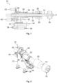
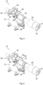
- the second positioning device 26 is in Fig. 1 not shown, since the corresponding ball screws are arranged outside the cross-sectional plane on the left and right, but is shown in the Fig. 2 to 4 clearly visible.
- the second slide 28 transmits the power of the second Positioning device 26 via push rods 32 to a cone mechanism 30, by means of which the first bellows carrier 20, which is arranged on the first sliding sleeve 18, can be expanded in the radial direction as a result of a displacement of the second carriage 28 relative to the first carriage 24.
- Fig. 2 visualizes the basic state of the device 10, wherein both the first carriage 24 and the second carriage 28 are moved back as far as possible.
- Fig. 3 illustrates starting from the basic position of the Fig. 2 the displacement of the first carriage 24 with the first positioning device 22.
- Fig. 4 shows the final state in which the second carriage 28 with the second positioning unit 26 has also been moved as far as possible in the direction of the tire building drum 16, whereby the expansion of the tire building drum 16, which is caused by the displacement of the second carriage 28, in the Fig. 3 is not shown for reasons of simplicity.
Landscapes
- Engineering & Computer Science (AREA)
- Mechanical Engineering (AREA)
- Manufacturing & Machinery (AREA)
- Tyre Moulding (AREA)
Applications Claiming Priority (1)
| Application Number | Priority Date | Filing Date | Title |
|---|---|---|---|
| DE102023206405.7A DE102023206405A1 (de) | 2023-07-06 | 2023-07-06 | Vorrichtung zum Aufbau einer Reifenkarkasse für einen Fahrzeugreifen |
Publications (1)
| Publication Number | Publication Date |
|---|---|
| EP4488043A1 true EP4488043A1 (fr) | 2025-01-08 |
Family
ID=91737772
Family Applications (1)
| Application Number | Title | Priority Date | Filing Date |
|---|---|---|---|
| EP24184860.5A Pending EP4488043A1 (fr) | 2023-07-06 | 2024-06-27 | Dispositif de montage d'une carcasse de pneu pour un pneu de véhicule |
Country Status (2)
| Country | Link |
|---|---|
| EP (1) | EP4488043A1 (fr) |
| DE (1) | DE102023206405A1 (fr) |
Cited By (1)
| Publication number | Priority date | Publication date | Assignee | Title |
|---|---|---|---|---|
| CN119928328A (zh) * | 2025-03-17 | 2025-05-06 | 中化学装备科技集团有限公司 | 鼓径可自动调节的贴合鼓 |
Citations (10)
| Publication number | Priority date | Publication date | Assignee | Title |
|---|---|---|---|---|
| US3676261A (en) | 1970-07-06 | 1972-07-11 | Goodyear Tire & Rubber | Bead setting and ply turnup apparatus |
| US3713950A (en) | 1970-04-30 | 1973-01-30 | Eagle Picher Ind Inc | Tire building machine with telescopic interconnection for mounting a bead ring holder |
| US3784437A (en) | 1969-11-28 | 1974-01-08 | Goodyear Tire & Rubber | Tire building apparatus |
| CN2875779Y (zh) | 2005-12-30 | 2007-03-07 | 郭洪生 | 反包式胶囊定型鼓 |
| CN200967277Y (zh) | 2006-11-03 | 2007-10-31 | 益阳新华美机电科技有限公司 | 轮胎成型机的反包胶囊装置 |
| DE102008037535A1 (de) | 2008-11-10 | 2010-05-12 | Continental Reifen Deutschland Gmbh | Vorrichtung zum Aufbau einer Reifenkarkasse für einen Fahrzeugreifen |
| US20150047771A1 (en) * | 2011-12-22 | 2015-02-19 | Mesnac Co., Ltd. | Tire building machine and boost turn-up method thereof |
| DE102013221967A1 (de) | 2013-10-29 | 2015-04-30 | Continental Reifen Deutschland Gmbh | Vorrichtung zur Herstellung eines Fahrzeugreifens |
| US11534996B2 (en) | 2016-05-23 | 2022-12-27 | Mesnac Co., Ltd. | Turn-up device and tire building method using turn-up device |
| EP4112287A1 (fr) * | 2021-06-28 | 2023-01-04 | Continental Reifen Deutschland GmbH | Machine de fabrication de pneus et procédé d'utilisation d'une machine de fabrication de pneus |
-
2023
- 2023-07-06 DE DE102023206405.7A patent/DE102023206405A1/de active Pending
-
2024
- 2024-06-27 EP EP24184860.5A patent/EP4488043A1/fr active Pending
Patent Citations (10)
| Publication number | Priority date | Publication date | Assignee | Title |
|---|---|---|---|---|
| US3784437A (en) | 1969-11-28 | 1974-01-08 | Goodyear Tire & Rubber | Tire building apparatus |
| US3713950A (en) | 1970-04-30 | 1973-01-30 | Eagle Picher Ind Inc | Tire building machine with telescopic interconnection for mounting a bead ring holder |
| US3676261A (en) | 1970-07-06 | 1972-07-11 | Goodyear Tire & Rubber | Bead setting and ply turnup apparatus |
| CN2875779Y (zh) | 2005-12-30 | 2007-03-07 | 郭洪生 | 反包式胶囊定型鼓 |
| CN200967277Y (zh) | 2006-11-03 | 2007-10-31 | 益阳新华美机电科技有限公司 | 轮胎成型机的反包胶囊装置 |
| DE102008037535A1 (de) | 2008-11-10 | 2010-05-12 | Continental Reifen Deutschland Gmbh | Vorrichtung zum Aufbau einer Reifenkarkasse für einen Fahrzeugreifen |
| US20150047771A1 (en) * | 2011-12-22 | 2015-02-19 | Mesnac Co., Ltd. | Tire building machine and boost turn-up method thereof |
| DE102013221967A1 (de) | 2013-10-29 | 2015-04-30 | Continental Reifen Deutschland Gmbh | Vorrichtung zur Herstellung eines Fahrzeugreifens |
| US11534996B2 (en) | 2016-05-23 | 2022-12-27 | Mesnac Co., Ltd. | Turn-up device and tire building method using turn-up device |
| EP4112287A1 (fr) * | 2021-06-28 | 2023-01-04 | Continental Reifen Deutschland GmbH | Machine de fabrication de pneus et procédé d'utilisation d'une machine de fabrication de pneus |
Cited By (1)
| Publication number | Priority date | Publication date | Assignee | Title |
|---|---|---|---|---|
| CN119928328A (zh) * | 2025-03-17 | 2025-05-06 | 中化学装备科技集团有限公司 | 鼓径可自动调节的贴合鼓 |
Also Published As
| Publication number | Publication date |
|---|---|
| DE102023206405A1 (de) | 2025-01-09 |
Similar Documents
| Publication | Publication Date | Title |
|---|---|---|
| DE69200204T2 (de) | Vorrichtung zum Formen ringförmiger Gegenstände. | |
| EP1731460B1 (fr) | Corps cylindrique d'une machine de traitement de matériau de bande imprimée | |
| EP0970770B1 (fr) | Dispositif et procédé pour l'usinage d'un alésage | |
| AT512987B1 (de) | Funkenerosions-Werkzeug und Elektrode für ein Funkenerosions-Werkzeug | |
| DE60036458T2 (de) | Drückwalzvorrichtung | |
| DE102007011849B4 (de) | Vorrichtung und Verfahren zum Biegen von flachem Halbzeug zu Profil mit über seine Länge veränderlichem Querschnitt | |
| DE4103160A1 (de) | Falzapparat mit einer vorrichtung zum verstellen von verstellbaren elementen eines falzwerkzylinders | |
| EP0769373B1 (fr) | Dispositif de changement des manchons de cylindres d'imprimerie dans les machines à imprimer | |
| DE102014118756A1 (de) | Messvorrichtung | |
| DE102011077569A1 (de) | Trommel | |
| EP2218542A2 (fr) | Lunettes de stabilisation | |
| DE10155256B4 (de) | Flexodruckmaschine mit alternativ manuell und automatisch anstellbaren Farbübertragungswalzen | |
| DE102023206405A1 (de) | Vorrichtung zum Aufbau einer Reifenkarkasse für einen Fahrzeugreifen | |
| DE102016100783A1 (de) | Winde für einen Zugstrang | |
| EP0554547A1 (fr) | Procédé pour la rectification de manetons de vibrequin et rectifieuse pour ce faire | |
| DE19530956A1 (de) | Vorrichtung zur Umstellung eines Sammelzylinders am Falzapparat | |
| DE102015207278A1 (de) | Elektrische Maschine und Transportvorrichtung für eine elektrische Maschine | |
| DE102017010743A1 (de) | Einspritzvorrichtung und Verfahren zum Einstellen der Position der axialen Mitte | |
| DE2144915B2 (de) | Vorrichtung zum aufbauen einer karkasse fuer fahrzeugluftreifen | |
| DE2146018C3 (de) | Anrollvorrichtung für eine Reifenaufbaumaschine | |
| DE4104354A1 (de) | Positioniereinrichtung mit einem zugseilsystem zum verschieben eines wagens sowie verfahren zu deren verwendung | |
| DE102012106656A1 (de) | Vorrichtung zum Aufwickeln von Reifenbauteilen auf einer Reifenaufbautrommel zur Herstellung eines Gürtel-Laufstreifenpaketes | |
| CH646630A5 (en) | Cutting device for the longitudinal cutting of a web of paper | |
| DE102017207673B4 (de) | Fräsvorrichtung mit verstellbarer Kopiereinrichtung | |
| EP1334283B1 (fr) | Unite soudee a palier lisse |
Legal Events
| Date | Code | Title | Description |
|---|---|---|---|
| PUAI | Public reference made under article 153(3) epc to a published international application that has entered the european phase |
Free format text: ORIGINAL CODE: 0009012 |
|
| STAA | Information on the status of an ep patent application or granted ep patent |
Free format text: STATUS: THE APPLICATION HAS BEEN PUBLISHED |
|
| AK | Designated contracting states |
Kind code of ref document: A1 Designated state(s): AL AT BE BG CH CY CZ DE DK EE ES FI FR GB GR HR HU IE IS IT LI LT LU LV MC ME MK MT NL NO PL PT RO RS SE SI SK SM TR |
|
| STAA | Information on the status of an ep patent application or granted ep patent |
Free format text: STATUS: REQUEST FOR EXAMINATION WAS MADE |
|
| 17P | Request for examination filed |
Effective date: 20250708 |